
Manual
Page 2
Motherboard GA-H61M-S2PV Oct. 28, 2011 Motherboard GA-H61M-S2PV Oct. 28, 2011
Motherboard GA-H61M-S2PV Oct. 28, 2011 Motherboard GA-H61M-S2PV Oct. 28, 2011
Manual
Page 4
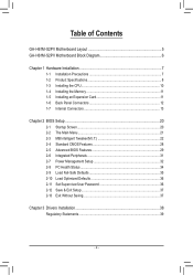
Table of Contents GA-H61M-S2PV Motherboard Layout 5 GA-H61M-S2PV Motherboard Block Diagram 6 Chapter 1 Hardware Installation 7 1-1 Installation Precautions 7 1-2 Product Specifications 8 1-3 Installing the CPU 10 1-4 Installing the Memory 11 1-5 Installing an Expansion Card 11 1-6 Back Panel ...
Table of Contents GA-H61M-S2PV Motherboard Layout 5 GA-H61M-S2PV Motherboard Block Diagram 6 Chapter 1 Hardware Installation 7 1-1 Installation Precautions 7 1-2 Product Specifications 8 1-3 Installing the CPU 10 1-4 Installing the Memory 11 1-5 Installing an Expansion Card 11 1-6 Back Panel ...
Manual
Page 5
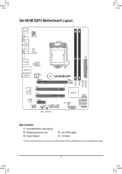
GA-H61M-S2PV Motherboard Layout VGA KB_MS ATX_12V LGA1155 LPT DVI CPU_FAN ATX R_USB USB_LAN Realtek/ Atheros GbE LAN AUDIO PCIe to PCI Bridge PCIEX16 BAT GA-H61M-S2PV DDR3_1 DDR3_2 B_BIOS M_BIOS iTE IT8728 PCI1 PCI2 CODEC PCIEX1 F_AUDIO F_USB2 F_USB1 COM SYS_FAN Intel® H61 SATA2 0 1 CLR_CMOS 2 3 F_PANEL Box Contents GA-H61M-S2PV motherboard Motherboard driver disk User's Manual Two SATA cables I/O Shield * The box contents above are for reference only and the actual items shall depend on the product package you obtain. - 5 -
GA-H61M-S2PV Motherboard Layout VGA KB_MS ATX_12V LGA1155 LPT DVI CPU_FAN ATX R_USB USB_LAN Realtek/ Atheros GbE LAN AUDIO PCIe to PCI Bridge PCIEX16 BAT GA-H61M-S2PV DDR3_1 DDR3_2 B_BIOS M_BIOS iTE IT8728 PCI1 PCI2 CODEC PCIEX1 F_AUDIO F_USB2 F_USB1 COM SYS_FAN Intel® H61 SATA2 0 1 CLR_CMOS 2 3 F_PANEL Box Contents GA-H61M-S2PV motherboard Motherboard driver disk User's Manual Two SATA cables I/O Shield * The box contents above are for reference only and the actual items shall depend on the product package you obtain. - 5 -
Manual
Page 6
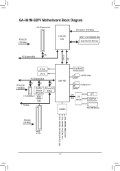
GA-H61M-S2PV Motherboard Block Diagram 1 PCI Express x16 CPU CLK+/- (100 MHz) PCIe CLK (100 MHz) LGA1155 CPU DDR3 1333/1066/800 MHz Dual Channel Memory DMI 2.0 FDI x16 PCI Express Bus D-Sub DVI-D PCI Express Bus PCIe CLK (100 MHz) x1 x1 Realtek/ Atheros GbE LAN 1 PCI Express x1 RJ45 x1 PCIe to PCI Bridge LAN PCI Bus Intel® H61 CODEC Dual BIOS 4 SATA 3Gb/s 8 USB 2.0/1.1 LPC Bus iTE IT8728 LPT COM Port PS/2 KB/Mouse PCI CLK (33 MHz) 2 PCI MIC (Center/Subwoofer Speaker Out) Line Out (Front Speaker Out) Line In (Rear Speaker Out) - 6 -
GA-H61M-S2PV Motherboard Block Diagram 1 PCI Express x16 CPU CLK+/- (100 MHz) PCIe CLK (100 MHz) LGA1155 CPU DDR3 1333/1066/800 MHz Dual Channel Memory DMI 2.0 FDI x16 PCI Express Bus D-Sub DVI-D PCI Express Bus PCIe CLK (100 MHz) x1 x1 Realtek/ Atheros GbE LAN 1 PCI Express x1 RJ45 x1 PCIe to PCI Bridge LAN PCI Bus Intel® H61 CODEC Dual BIOS 4 SATA 3Gb/s 8 USB 2.0/1.1 LPC Bus iTE IT8728 LPT COM Port PS/2 KB/Mouse PCI CLK (33 MHz) 2 PCI MIC (Center/Subwoofer Speaker Out) Line Out (Front Speaker Out) Line In (Rear Speaker Out) - 6 -
Manual
Page 16
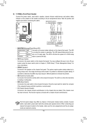
F_AUDIO(H) F_PANEL(NH) 2 1 20 F_PANEL 19 (H61M-D2) HD+ HD- Hard Drive Reset Activity LED Switch Power ... computer freezes and fails to perform a normal restart. •• CI (Chassis Intrusion Header): GP15_CPT (GA-IVB) Connects to the chassis intrusion switch/sensor on the chassis front panel. When connecting your chassis front ...heard if no problem is - This function requires a chassis with a chassis intrusion switch/sensor. XDP_CPU XDP_PCH (GA-IVB) The front panel design may differ by is detected at system sStMaBrt_uCpP.TIf PCIe power conanepcrtoorb(lSeAmTAi)s(Xd58eAt-eOcCte...
F_AUDIO(H) F_PANEL(NH) 2 1 20 F_PANEL 19 (H61M-D2) HD+ HD- Hard Drive Reset Activity LED Switch Power ... computer freezes and fails to perform a normal restart. •• CI (Chassis Intrusion Header): GP15_CPT (GA-IVB) Connects to the chassis intrusion switch/sensor on the chassis front panel. When connecting your chassis front ...heard if no problem is - This function requires a chassis with a chassis intrusion switch/sensor. XDP_CPU XDP_PCH (GA-IVB) The front panel design may differ by is detected at system sStMaBrt_uCpP.TIf PCIe power conanepcrtoorb(lSeAmTAi)s(Xd58eAt-eOcCte...


