
Manual
Page 2
Motherboard GA-H61M-S2PV Oct. 28, 2011 Motherboard GA-H61M-S2PV Oct. 28, 2011
Motherboard GA-H61M-S2PV Oct. 28, 2011 Motherboard GA-H61M-S2PV Oct. 28, 2011

Manual
Page 3
... and is 1.0. Example: Disclaimer Information in this manual are legally registered to assist in this manual is protected by GIGABYTE without GIGABYTE's prior written permission. In order to their respective owners. Check your motherboard looks like this manual may be reproduced, copied, translated, transmitted, or published in this : "REV: X.X." For example, "REV...
... and is 1.0. Example: Disclaimer Information in this manual are legally registered to assist in this manual is protected by GIGABYTE without GIGABYTE's prior written permission. In order to their respective owners. Check your motherboard looks like this manual may be reproduced, copied, translated, transmitted, or published in this : "REV: X.X." For example, "REV...
Manual
Page 4
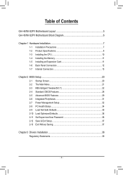
Table of Contents GA-H61M-S2PV Motherboard Layout 5 GA-H61M-S2PV Motherboard Block Diagram 6 Chapter 1 Hardware Installation 7 1-1 Installation Precautions 7 1-2 Product Specifications 8 1-3 Installing the CPU 10 1-4 Installing the Memory 11 1-5 Installing an Expansion Card 11 1-6 Back Panel Connectors ...
Table of Contents GA-H61M-S2PV Motherboard Layout 5 GA-H61M-S2PV Motherboard Block Diagram 6 Chapter 1 Hardware Installation 7 1-1 Installation Precautions 7 1-2 Product Specifications 8 1-3 Installing the CPU 10 1-4 Installing the Memory 11 1-5 Installing an Expansion Card 11 1-6 Back Panel Connectors ...
Manual
Page 5
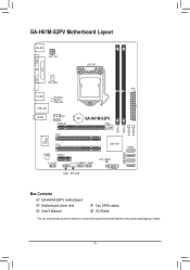
GA-H61M-S2PV Motherboard Layout VGA KB_MS ATX_12V LGA1155 LPT DVI CPU_FAN ATX R_USB USB_LAN Realtek/ Atheros GbE LAN AUDIO PCIe to PCI Bridge PCIEX16 BAT GA-H61M-S2PV DDR3_1 DDR3_2 B_BIOS M_BIOS iTE IT8728 PCI1 PCI2 CODEC PCIEX1 F_AUDIO F_USB2 F_USB1 COM SYS_FAN Intel® H61 SATA2 0 1 CLR_CMOS 2 3 F_PANEL Box Contents GA-H61M-S2PV motherboard Motherboard driver disk User's Manual Two SATA cables I/O Shield * The box contents above are for reference only and the actual items shall depend on the product package you obtain. - 5 -
GA-H61M-S2PV Motherboard Layout VGA KB_MS ATX_12V LGA1155 LPT DVI CPU_FAN ATX R_USB USB_LAN Realtek/ Atheros GbE LAN AUDIO PCIe to PCI Bridge PCIEX16 BAT GA-H61M-S2PV DDR3_1 DDR3_2 B_BIOS M_BIOS iTE IT8728 PCI1 PCI2 CODEC PCIEX1 F_AUDIO F_USB2 F_USB1 COM SYS_FAN Intel® H61 SATA2 0 1 CLR_CMOS 2 3 F_PANEL Box Contents GA-H61M-S2PV motherboard Motherboard driver disk User's Manual Two SATA cables I/O Shield * The box contents above are for reference only and the actual items shall depend on the product package you obtain. - 5 -
Manual
Page 6
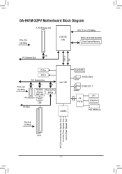
GA-H61M-S2PV Motherboard Block Diagram 1 PCI Express x16 CPU CLK+/- (100 MHz) PCIe CLK (100 MHz) LGA1155 CPU DDR3 1333/1066/800 MHz Dual Channel Memory DMI 2.0 FDI x16 PCI Express Bus D-Sub DVI-D PCI Express Bus PCIe CLK (100 MHz) x1 x1 Realtek/ Atheros GbE LAN 1 PCI Express x1 RJ45 x1 PCIe to PCI Bridge LAN PCI Bus Intel® H61 CODEC Dual BIOS 4 SATA 3Gb/s 8 USB 2.0/1.1 LPC Bus iTE IT8728 LPT COM Port PS/2 KB/Mouse PCI CLK (33 MHz) 2 PCI MIC (Center/Subwoofer Speaker Out) Line Out (Front Speaker Out) Line In (Rear Speaker Out) - 6 -
GA-H61M-S2PV Motherboard Block Diagram 1 PCI Express x16 CPU CLK+/- (100 MHz) PCIe CLK (100 MHz) LGA1155 CPU DDR3 1333/1066/800 MHz Dual Channel Memory DMI 2.0 FDI x16 PCI Express Bus D-Sub DVI-D PCI Express Bus PCIe CLK (100 MHz) x1 x1 Realtek/ Atheros GbE LAN 1 PCI Express x1 RJ45 x1 PCIe to PCI Bridge LAN PCI Bus Intel® H61 CODEC Dual BIOS 4 SATA 3Gb/s 8 USB 2.0/1.1 LPC Bus iTE IT8728 LPT COM Port PS/2 KB/Mouse PCI CLK (33 MHz) 2 PCI MIC (Center/Subwoofer Speaker Out) Line Out (Front Speaker Out) Line In (Rear Speaker Out) - 6 -
Manual
Page 7
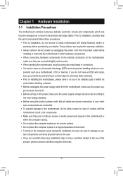
...wear an electrostatic discharge (ESD) wrist strap when handling electronic com- ponents such as a motherboard, CPU or memory. Chapter 1 Hardware Installation 1-1 Installation Precautions The motherboard contains numerous delicate electronic circuits and components which can lead to damage to system components as well... an ESD wrist strap, keep your hardware components are connected. •• To prevent damage to the motherboard, do not remove or break motherboard S/N (Serial Number) sticker or warranty sticker provided by unplugging the power cord from the power outlet before ...
...wear an electrostatic discharge (ESD) wrist strap when handling electronic com- ponents such as a motherboard, CPU or memory. Chapter 1 Hardware Installation 1-1 Installation Precautions The motherboard contains numerous delicate electronic circuits and components which can lead to damage to system components as well... an ESD wrist strap, keep your hardware components are connected. •• To prevent damage to the motherboard, do not remove or break motherboard S/N (Serial Number) sticker or warranty sticker provided by unplugging the power cord from the power outlet before ...
Manual
Page 9
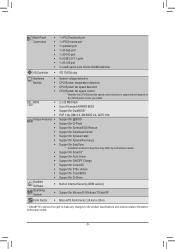
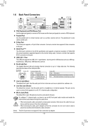
... Support for 3TB+ Unlock Support for TouchBIOS Support for Q-Share Norton Internet Security (OEM version) Support for EasyTune * Available functions in EasyTune may differ by motherboard model. Back Panel Connectors ŠŠ 1 x PS/2 keyboard port ŠŠ 1 x PS/2 mouse port ŠŠ 1 x parallel port ŠŠ 1 x D-Sub ... Support for Microsoft® Windows 7/Vista/XP Form Factor ŠŠ Micro ATX Form Factor; 24.4cm x 20cm * GIGABYTE reserves the right to make any changes to the product specifications and product-related information without prior notice. - 9 -
... Support for 3TB+ Unlock Support for TouchBIOS Support for Q-Share Norton Internet Security (OEM version) Support for EasyTune * Available functions in EasyTune may differ by motherboard model. Back Panel Connectors ŠŠ 1 x PS/2 keyboard port ŠŠ 1 x PS/2 mouse port ŠŠ 1 x parallel port ŠŠ 1 x D-Sub ... Support for Microsoft® Windows 7/Vista/XP Form Factor ŠŠ Micro ATX Form Factor; 24.4cm x 20cm * GIGABYTE reserves the right to make any changes to the product specifications and product-related information without prior notice. - 9 -
Manual
Page 10
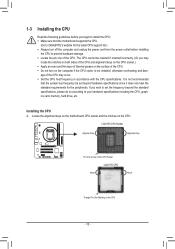
... the CPU Socket LGA1155 CPU Notch Notch Triangle Pin One Marking on the computer if the CPU cooler is not recommended that the motherboard supports the CPU. (Go to GIGABYTE's website for the peripherals. If you begin to install the CPU: •• Make sure that the system bus frequency be inserted... not meet the standard requirements for the latest CPU support list.) •• Always turn on the CPU - 10 - Locate the alignment keys on the motherboard CPU socket and the notches on the CPU. It is not installed, otherwise overheating and dam-
... the CPU Socket LGA1155 CPU Notch Notch Triangle Pin One Marking on the computer if the CPU cooler is not recommended that the motherboard supports the CPU. (Go to GIGABYTE's website for the peripherals. If you begin to install the CPU: •• Make sure that the system bus frequency be inserted... not meet the standard requirements for the latest CPU support list.) •• Always turn on the CPU - 10 - Locate the alignment keys on the motherboard CPU socket and the notches on the CPU. It is not installed, otherwise overheating and dam-
Manual
Page 11
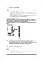
... mode. 111 Dual Channel mode cannot be used . (Go to GIGABYTE's website for optimum performance. 1-5 Installing an Expansion Card Read the following guidelines before you begin to install an expansion card: •• Make sure the motherboard supports the expansion card. After the memory is recommended that came with.... DDR3_1 DDR3_2 1-4 Installing the Memory Read the following guidelines before you begin to install the memory: •• Make sure that the motherboard supports the memory. If you are divided into two channels and each channel has one direction.
... mode. 111 Dual Channel mode cannot be used . (Go to GIGABYTE's website for optimum performance. 1-5 Installing an Expansion Card Read the following guidelines before you begin to install an expansion card: •• Make sure the motherboard supports the expansion card. After the memory is recommended that came with.... DDR3_1 DDR3_2 1-4 Installing the Memory Read the following guidelines before you begin to install the memory: •• Make sure that the motherboard supports the memory. If you are divided into two channels and each channel has one direction.
Manual
Page 12
... 2.0/1.1 Port The USB port supports the USB 2.0/1.1 specification. Mic In Jack (Pink) The default Mic in jack. Do not rock it straight out from the motherboard. •• When removing the cable, pull it side to side to this audio jack for a headphone or 2-channel speaker. Connect a monitor that supports D-Sub...
... 2.0/1.1 Port The USB port supports the USB 2.0/1.1 specification. Mic In Jack (Pink) The default Mic in jack. Do not rock it straight out from the motherboard. •• When removing the cable, pull it side to side to this audio jack for a headphone or 2-channel speaker. Connect a monitor that supports D-Sub...
Manual
Page 13
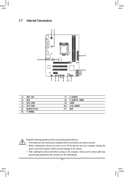
... and your devices are compliant with the connectors you wish to connect. •• Before installing the devices, be sure to the connector on the motherboard. - 13 -
... and your devices are compliant with the connectors you wish to connect. •• Before installing the devices, be sure to the connector on the motherboard. - 13 -

Manual
Page 14
If a power supply is turned off and all the components on the motherboard. The 12V power connector mainly supplies power to the power connector in the correct orientation. Before connecting the power connector, first make sure the power ...
If a power supply is turned off and all the components on the motherboard. The 12V power connector mainly supplies power to the power connector in the correct orientation. Before connecting the power connector, first make sure the power ...

Manual
Page 15
...chassis. 1 CPU_FAN 1 SYS_FAN CPU_FAN/SYS_FAN:: Pin No. Over- Each SATA connector supports a single SATA device. heating may hang. The motherboard supports CPU fan speed control, which requires the use of the SATA cable to SATA 3Gb/s standard and are not configuration jumper blocks. ...3/4) CPU_FAN/SYS_FAN (Fan Headers) The motherboard has a 4-pin CPU fan header (CPU_FAN), a 4-pin system fan header (SYS_FAN). Definition 1 GND 2 +12V 3 Sense 4 Speed Control...
...chassis. 1 CPU_FAN 1 SYS_FAN CPU_FAN/SYS_FAN:: Pin No. Over- Each SATA connector supports a single SATA device. heating may hang. The motherboard supports CPU fan speed control, which requires the use of the SATA cable to SATA 3Gb/s standard and are not configuration jumper blocks. ...3/4) CPU_FAN/SYS_FAN (Fan Headers) The motherboard has a 4-pin CPU fan header (CPU_FAN), a 4-pin system fan header (SYS_FAN). Definition 1 GND 2 +12V 3 Sense 4 Speed Control...
Manual
Page 17
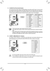
... audio module to USB 2.0/1.1 specification. Definition Pin No. For information about connecting the front panel audio module that has separated connectors on both of the motherboard header. Each USB header can provide two USB ports via an optional USB bracket. Make sure the wire assignments of the module connector match the...
... audio module to USB 2.0/1.1 specification. Definition Pin No. For information about connecting the front panel audio module that has separated connectors on both of the motherboard header. Each USB header can provide two USB ports via an optional USB bracket. Make sure the wire assignments of the module connector match the...
Manual
Page 20
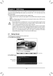
...press + in the main menu of the BIOS Setup program. H61M-S2PV FA . . . . : BIOS Setup : XpressRecovery2 : Boot Menu : Qflash 10/05/2011-H61-7A89XG0MC-00 Function Keys Function Keys - 20 - To upgrade the BIOS, use either the GIGABYTE Q-Flash or @BIOS utility. •• Q-Flash allows ...the user to prevent system instability or other unexpected results. To flash the BIOS, do not encounter problems using the current version of BIOS, it with caution. The POST Screen Motherboard Model BIOS Version...
...press + in the main menu of the BIOS Setup program. H61M-S2PV FA . . . . : BIOS Setup : XpressRecovery2 : Boot Menu : Qflash 10/05/2011-H61-7A89XG0MC-00 Function Keys Function Keys - 20 - To upgrade the BIOS, use either the GIGABYTE Q-Flash or @BIOS utility. •• Q-Flash allows ...the user to prevent system instability or other unexpected results. To flash the BIOS, do not encounter problems using the current version of BIOS, it with caution. The POST Screen Motherboard Model BIOS Version...
Manual
Page 32
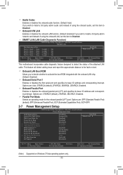
...; Move Enter: Select F5: Previous Values +/-/PU/PD: Value F10: Save F6: Fail-Safe Defaults ESC: Exit F1: General Help F7: Optimized Defaults This motherboard incorporates cable diagnostic feature designed to detect the status of Month) Alarm x Time (hh:mm:ss) Alarm HPET Support (Note) HPET Mode (Note) Power On...
...; Move Enter: Select F5: Previous Values +/-/PU/PD: Value F10: Save F6: Fail-Safe Defaults ESC: Exit F1: General Help F7: Optimized Defaults This motherboard incorporates cable diagnostic feature designed to detect the status of Month) Alarm x Time (hh:mm:ss) Alarm HPET Support (Note) HPET Mode (Note) Power On...

Manual
Page 34
...-On The system is set to Enabled, the following four functions will become unavailable: PME event wake up to 5 characters and then press to the motherboard CI header. When prompted for the password, press again without entering the password to the CMOS, and then restart your system. Soft-Off The system...
...-On The system is set to Enabled, the following four functions will become unavailable: PME event wake up to 5 characters and then press to the motherboard CI header. When prompted for the password, press again without entering the password to the CMOS, and then restart your system. Soft-Off The system...
Manual
Page 35
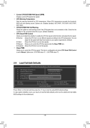
CPU Warning Temperature Sets the warning threshold for the motherboard. - 35 - Manual Allows you to the CPU temperature. Disabled Allows the CPU fan to run at different speeds according to control the CPU fan speed. ...
CPU Warning Temperature Sets the warning threshold for the motherboard. - 35 - Manual Allows you to the CPU temperature. Disabled Allows the CPU fan to run at different speeds according to control the CPU fan speed. ...
Manual
Page 38
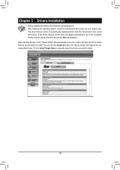
... to install. Chapter 3 Drivers Installation •• Before installing the drivers, first install the operating system. •• After installing the operating system, insert the motherboard driver disk into your system and then list all the recommended drivers. The driver Autorun screen is automatically displayed which looks like that shown in...
... to install. Chapter 3 Drivers Installation •• Before installing the drivers, first install the operating system. •• After installing the operating system, insert the motherboard driver disk into your system and then list all the recommended drivers. The driver Autorun screen is automatically displayed which looks like that shown in...
Manual
Page 39
...materials in Electrical and Electronic Equipment) and WEEE (Waste Electrical and Electronic Equipment) environmental directives, as well as a commitment by GIGABYTE. Under the Directive, used for the disposal of "end of life" products, and generally improve our quality of life by ensuring...and components have not intended to meet RoHS requirement. Moreover, we suggest that the information contained herein was delivered in all GIGABYTE motherboards fulfill European Union regulations for errors or omissions in your product's user's manual and we can reduce the amount of natural...
...materials in Electrical and Electronic Equipment) and WEEE (Waste Electrical and Electronic Equipment) environmental directives, as well as a commitment by GIGABYTE. Under the Directive, used for the disposal of "end of life" products, and generally improve our quality of life by ensuring...and components have not intended to meet RoHS requirement. Moreover, we suggest that the information contained herein was delivered in all GIGABYTE motherboards fulfill European Union regulations for errors or omissions in your product's user's manual and we can reduce the amount of natural...


