Manual
Page 2
Motherboard GA-H61M-S2P-B3 Jun. 10, 2011 Motherboard GA-H61M-S2P-B3 Jun. 10, 2011
Motherboard GA-H61M-S2P-B3 Jun. 10, 2011 Motherboard GA-H61M-S2P-B3 Jun. 10, 2011
Manual
Page 3
... means without prior notice. Example: All rights reserved. Disclaimer Information in this manual may be reproduced, copied, translated, transmitted, or published in the use of GIGABYTE. Check your motherboard looks like this product, carefully read the User's Manual. For product-related information, check on our website at: http://www...
... means without prior notice. Example: All rights reserved. Disclaimer Information in this manual may be reproduced, copied, translated, transmitted, or published in the use of GIGABYTE. Check your motherboard looks like this product, carefully read the User's Manual. For product-related information, check on our website at: http://www...
Manual
Page 4
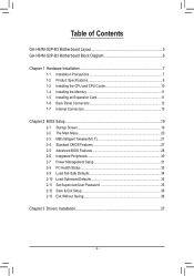
Table of Contents GA-H61M-S2P-B3 Motherboard Layout 5 GA-H61M-S2P-B3 Motherboard Block Diagram 6 Chapter 1 Hardware Installation 7 1-1 Installation Precautions 7 1-2 Product Specifications 8 1-3 Installing the CPU and CPU Cooler 10 1-4 Installing the Memory 11 1-5 Installing an Expansion Card 11 1-6 ...
Table of Contents GA-H61M-S2P-B3 Motherboard Layout 5 GA-H61M-S2P-B3 Motherboard Block Diagram 6 Chapter 1 Hardware Installation 7 1-1 Installation Precautions 7 1-2 Product Specifications 8 1-3 Installing the CPU and CPU Cooler 10 1-4 Installing the Memory 11 1-5 Installing an Expansion Card 11 1-6 ...
Manual
Page 5
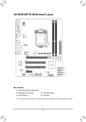
GA-H61M-S2P-B3 Motherboard Layout KB_MS ATX_12V LGA1155 VGA COM LPT CPU_FAN R_USB USB_LAN Atheros AR8151 AUDIO PCIe to PCI Bridge PCIEX16 BAT GA-H61M-S2P-B3 iTE IT8728 PCI1 PCI2 Intel® H61 CODEC PCIEX1 F_AUDIO SYS_FAN F_USB2 F_USB1 CLR_CMOS F_PANEL DDR3_1 DDR3_2 B_BIOS M_BIOS ATX SATA2_0 SATA2_1 SATA2_2 SATA2_3 Box Contents GA-H61M-S2P-B3 motherboard Motherboard driver disk User's Manual Two SATA cables I/O Shield * The box contents above are for reference only and the actual items shall depend on the product package you obtain. - 5 -
GA-H61M-S2P-B3 Motherboard Layout KB_MS ATX_12V LGA1155 VGA COM LPT CPU_FAN R_USB USB_LAN Atheros AR8151 AUDIO PCIe to PCI Bridge PCIEX16 BAT GA-H61M-S2P-B3 iTE IT8728 PCI1 PCI2 Intel® H61 CODEC PCIEX1 F_AUDIO SYS_FAN F_USB2 F_USB1 CLR_CMOS F_PANEL DDR3_1 DDR3_2 B_BIOS M_BIOS ATX SATA2_0 SATA2_1 SATA2_2 SATA2_3 Box Contents GA-H61M-S2P-B3 motherboard Motherboard driver disk User's Manual Two SATA cables I/O Shield * The box contents above are for reference only and the actual items shall depend on the product package you obtain. - 5 -
Manual
Page 6
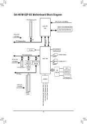
GA-H61M-S2P-B3 Motherboard Block Diagram 1 PCI Express x16 CPU CLK+/- (100 MHz) LGA1155 CPU DDR3 1333/1066/800 MHz Dual Channel Memory PCIe CLK (100 MHz) x16 PCI Express Bus DMI 2.0 FDI D-Sub Dual BIOS PCI Express Bus PCIe CLK (100 MHz) x1 x1 x1 Atheros PCIe to PCI AR8151 Bridge 1 PCI Express x1 RJ45 LAN PCI Bus Intel® H61 4 SATA 3Gb/s 8 USB 2.0/1.1 LPC Bus iTE IT8728 LPT COM Port CODEC PS/2 KB/Mouse PCI CLK (33 MHz) 2 PCI MIC (Center/Subwoofer Speaker Out) Line Out (Front Speaker Out) Line In (Rear Speaker Out) - 6 -
GA-H61M-S2P-B3 Motherboard Block Diagram 1 PCI Express x16 CPU CLK+/- (100 MHz) LGA1155 CPU DDR3 1333/1066/800 MHz Dual Channel Memory PCIe CLK (100 MHz) x16 PCI Express Bus DMI 2.0 FDI D-Sub Dual BIOS PCI Express Bus PCIe CLK (100 MHz) x1 x1 x1 Atheros PCIe to PCI AR8151 Bridge 1 PCI Express x1 RJ45 LAN PCI Bus Intel® H61 4 SATA 3Gb/s 8 USB 2.0/1.1 LPC Bus iTE IT8728 LPT COM Port CODEC PS/2 KB/Mouse PCI CLK (33 MHz) 2 PCI MIC (Center/Subwoofer Speaker Out) Line Out (Front Speaker Out) Line In (Rear Speaker Out) - 6 -
Manual
Page 7
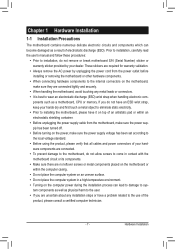
...ESD). These stickers are required for warranty validation. •• Always remove the AC power by unplugging the power cord from the motherboard, make sure the power supply has been turned off. •• Before turning on the power, make sure they are connected ... is best to wear an electrostatic discharge (ESD) wrist strap when handling electronic com- Chapter 1 Hardware Installation 1-1 Installation Precautions The motherboard contains numerous delicate electronic circuits and components which can lead to damage to system components as well as physical harm to the user. ...
...ESD). These stickers are required for warranty validation. •• Always remove the AC power by unplugging the power cord from the motherboard, make sure the power supply has been turned off. •• Before turning on the power, make sure they are connected ... is best to wear an electrostatic discharge (ESD) wrist strap when handling electronic com- Chapter 1 Hardware Installation 1-1 Installation Precautions The motherboard contains numerous delicate electronic circuits and components which can lead to damage to system components as well as physical harm to the user. ...
Manual
Page 9
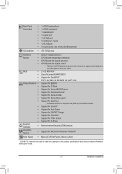
...Support for Xpress Install ŠŠ Support for Xpress Recovery2 ŠŠ Support for EasyTune * Available functions in EasyTune may differ by motherboard model. ŠŠ Support for Smart 6™ ŠŠ Support for Auto Green ŠŠ Support for ON/OFF Charge...System ŠŠ Support for Microsoft® Windows 7/Vista/XP Form Factor ŠŠ Micro ATX Form Factor; 24.4cm x 20cm * GIGABYTE reserves the right to make any changes to the product specifications and product-related information without prior notice. - 9 - Back Panel Connectors Š&#...
...Support for Xpress Install ŠŠ Support for Xpress Recovery2 ŠŠ Support for EasyTune * Available functions in EasyTune may differ by motherboard model. ŠŠ Support for Smart 6™ ŠŠ Support for Auto Green ŠŠ Support for ON/OFF Charge...System ŠŠ Support for Microsoft® Windows 7/Vista/XP Form Factor ŠŠ Micro ATX Form Factor; 24.4cm x 20cm * GIGABYTE reserves the right to make any changes to the product specifications and product-related information without prior notice. - 9 - Back Panel Connectors Š&#...
Manual
Page 10
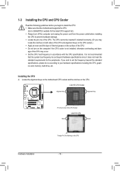
It is not installed, otherwise overheating and dam- Locate the alignment keys on the motherboard CPU socket and the notches on the CPU Hardware Installation - 10 - If you may occur. •• Set the CPU host frequency in accordance with ....) •• Apply an even and thin layer of thermal grease on the computer if the CPU cooler is not recommended that the motherboard supports the CPU. (Go to GIGABYTE's website for the peripherals. The CPU cannot be set the frequency beyond hardware specifications since it does not meet the standard requirements...
It is not installed, otherwise overheating and dam- Locate the alignment keys on the motherboard CPU socket and the notches on the CPU Hardware Installation - 10 - If you may occur. •• Set the CPU host frequency in accordance with ....) •• Apply an even and thin layer of thermal grease on the computer if the CPU cooler is not recommended that the motherboard supports the CPU. (Go to GIGABYTE's website for the peripherals. The CPU cannot be set the frequency beyond hardware specifications since it does not meet the standard requirements...
Manual
Page 11
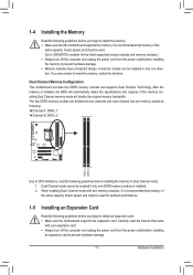
.... 1-4 Installing the Memory Read the following guidelines before you begin to install the memory: •• Make sure that the motherboard supports the memory. If you are divided into two channels and each channel has one DDR3 memory module is installed. 222 When ...are unable to install an expansion card: •• Make sure the motherboard supports the expansion card. It is installed, the BIOS will double the original memory bandwidth. A memory module can be used . (Go to GIGABYTE's website for optimum performance. 1-5 Installing an Expansion Card Read the following...
.... 1-4 Installing the Memory Read the following guidelines before you begin to install the memory: •• Make sure that the motherboard supports the memory. If you are divided into two channels and each channel has one DDR3 memory module is installed. 222 When ...are unable to install an expansion card: •• Make sure the motherboard supports the expansion card. It is installed, the BIOS will double the original memory bandwidth. A memory module can be used . (Go to GIGABYTE's website for optimum performance. 1-5 Installing an Expansion Card Read the following...
Manual
Page 12
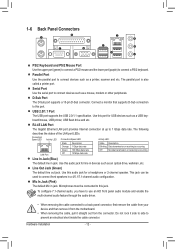
... Ethernet LAN port provides Internet connection at up to a back panel connector, first remove the cable from your device and then remove it from the motherboard. •• When removing the cable, pull it side to side to connect devices such as a USB keyboard/mouse, USB printer, USB flash drive and...
... Ethernet LAN port provides Internet connection at up to a back panel connector, first remove the cable from your device and then remove it from the motherboard. •• When removing the cable, pull it side to side to connect devices such as a USB keyboard/mouse, USB printer, USB flash drive and...
Manual
Page 13
... and your devices are compliant with the connectors you wish to connect. •• Before installing the devices, be sure to the connector on the motherboard. - 13 - Hardware Installation
... and your devices are compliant with the connectors you wish to connect. •• Before installing the devices, be sure to the connector on the motherboard. - 13 - Hardware Installation

Manual
Page 14
If the 12V power connector is turned off and all the components on the motherboard. 1/2) ATX_12V/ATX (2x2 12V Power Connector and 2x12 Main Power Connector) With the use of the power connector, the power supply can withstand high power ...
If the 12V power connector is turned off and all the components on the motherboard. 1/2) ATX_12V/ATX (2x2 12V Power Connector and 2x12 Main Power Connector) With the use of the power connector, the power supply can withstand high power ...
Manual
Page 15
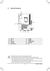
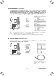
... the headers. Please connect the L-shaped end of a CPU fan with SATA 1.5Gb/s standard. heating may hang. The motherboard supports CPU fan speed control, which requires the use of the SATA cable to prevent your SATA hard drive. Each SATA ... SATA2_2 1 7 SATA2_3 1 7 Pin No. 1 2 3 4 5 6 7 Definition GND TXP TXN GND RXN RXP GND - 15 - 3/4) CPU_FAN/SYS_FAN (Fan Headers) The motherboard has a 4-pin CPU fan header (CPU_FAN), a 4-pin system fan header (SYS_FAN). Most fan headers possess a foolproof insertion design. DEBUG PORT 5) SATA2_0/1/2/3 (SATA 3Gb/s Connectors)...
... the headers. Please connect the L-shaped end of a CPU fan with SATA 1.5Gb/s standard. heating may hang. The motherboard supports CPU fan speed control, which requires the use of the SATA cable to prevent your SATA hard drive. Each SATA ... SATA2_2 1 7 SATA2_3 1 7 Pin No. 1 2 3 4 5 6 7 Definition GND TXP TXN GND RXN RXP GND - 15 - 3/4) CPU_FAN/SYS_FAN (Fan Headers) The motherboard has a 4-pin CPU fan header (CPU_FAN), a 4-pin system fan header (SYS_FAN). Most fan headers possess a foolproof insertion design. DEBUG PORT 5) SATA2_0/1/2/3 (SATA 3Gb/s Connectors)...

Manual
Page 17
... the IEEE 1394 bracket (2x5-pin) cable into the USB header. •• Prior to this header. Incorrect connection between the module connector and the motherboard header will be sure to turn off your chassis front panel audio module to installing the USB bracket, be present on each wire instead of...
... the IEEE 1394 bracket (2x5-pin) cable into the USB header. •• Prior to this header. Incorrect connection between the module connector and the motherboard header will be sure to turn off your chassis front panel audio module to installing the USB bracket, be present on each wire instead of...
Manual
Page 18
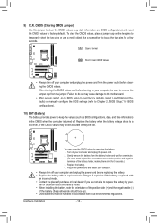
... be accurate or may be handled in the power cord and restart your computer. •• Always turn off . You may cause damage to the motherboard. •• After system restart, go to BIOS Setup to load factory defaults (select Load Optimized Defaults) or manually configure the BIOS settings (refer to...
... be accurate or may be handled in the power cord and restart your computer. •• Always turn off . You may cause damage to the motherboard. •• After system restart, go to BIOS Setup to load factory defaults (select Load Optimized Defaults) or manually configure the BIOS settings (refer to...
Manual
Page 19
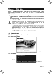
To upgrade the BIOS, use either the GIGABYTE Q-Flash or @BIOS utility. •• Q-Flash allows the user to quickly and easily upgrade or back up BIOS without entering the operating system. •&#... caution. The POST Screen Motherboard Model BIOS Version Award Modular BIOS v6.00PG Copyright (C) 1984-2011, Award Software, Inc. A. The LOGO Screen (Default): B. Inadequately altering the settings may result in this occurs, try to clear the CMOS values and reset the board to default values. (Refer to boot. H61M-S2P-B3 E2 . . . . : BIOS Setup...
To upgrade the BIOS, use either the GIGABYTE Q-Flash or @BIOS utility. •• Q-Flash allows the user to quickly and easily upgrade or back up BIOS without entering the operating system. •&#... caution. The POST Screen Motherboard Model BIOS Version Award Modular BIOS v6.00PG Copyright (C) 1984-2011, Award Software, Inc. A. The LOGO Screen (Default): B. Inadequately altering the settings may result in this occurs, try to clear the CMOS values and reset the board to default values. (Refer to boot. H61M-S2P-B3 E2 . . . . : BIOS Setup...
Manual
Page 33
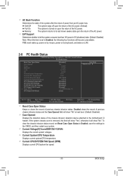
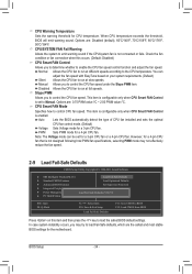
..." at next boot. (Default: Disabled) Case Opened Displays the detection status of the AC power. To clear the chassis intrusion status record, set to the motherboard CI header. BIOS Setup AC Back Function Determines the state of the system after the return of the AC power. Current System/CPU Temperature Displays...
..." at next boot. (Default: Disabled) Case Opened Displays the detection status of the AC power. To clear the chassis intrusion status record, set to the motherboard CI header. BIOS Setup AC Back Function Determines the state of the system after the return of the AC power. Current System/CPU Temperature Displays...
Manual
Page 34
... occurs, you to determine whether to emit warning sound if the CPU/system fan is enabled. CPU Warning Temperature Sets the warning threshold for the motherboard. Options are the safest and most stable BIOS settings for CPU temperature. You can be set to load Fail-Safe defaults, which are : 0.75 PWM...
... occurs, you to determine whether to emit warning sound if the CPU/system fan is enabled. CPU Warning Temperature Sets the warning threshold for the motherboard. Options are the safest and most stable BIOS settings for CPU temperature. You can be set to load Fail-Safe defaults, which are : 0.75 PWM...

Manual
Page 37
BIOS Setup Chapter 3 Drivers Installation •• Before installing the drivers, first install the operating system. •• After installing the operating system, insert the motherboard driver disk into your system and then list all the recommended drivers. Or click Install Single Items to manually select the drivers you wish to ...
BIOS Setup Chapter 3 Drivers Installation •• Before installing the drivers, first install the operating system. •• After installing the operating system, insert the motherboard driver disk into your system and then list all the recommended drivers. Or click Install Single Items to manually select the drivers you wish to ...


