
Manual
Page 1
GA-H55M-UD2H/ GA-H55M-US2H LGA1156 socket motherboard for Intel® Core™ i7 processor family/ Intel® Core™ i5 processor family/ Intel® Core™ i3 processor family User's Manual Rev. 1002 12ME-H55MUD2-1002R
GA-H55M-UD2H/ GA-H55M-US2H LGA1156 socket motherboard for Intel® Core™ i7 processor family/ Intel® Core™ i5 processor family/ Intel® Core™ i3 processor family User's Manual Rev. 1002 12ME-H55MUD2-1002R

Manual
Page 2
Motherboard GA-H55M-UD2H/GA-H55M-US2H Nov. 14, 2009 Motherboard GA-H55M-UD2H/ GA-H55M-US2H Nov. 14, 2009
Motherboard GA-H55M-UD2H/GA-H55M-US2H Nov. 14, 2009 Motherboard GA-H55M-UD2H/ GA-H55M-US2H Nov. 14, 2009

Manual
Page 3
... manual may be made by any form or by GIGABYTE without GIGABYTE's prior written permission. Check your motherboard looks like this manual may be reproduced, copied, translated, transmitted, or published in the use GIGABYTE's unique features, read the User's Manual. Changes ...this manual are legally registered to use of this product, GIGABYTE provides the following types of documentations: For quick set-up of this : "REV: X.X." For instructions on your motherboard revision before updating motherboard BIOS, drivers, or when looking for technical information. All...
... manual may be made by any form or by GIGABYTE without GIGABYTE's prior written permission. Check your motherboard looks like this manual may be reproduced, copied, translated, transmitted, or published in the use GIGABYTE's unique features, read the User's Manual. Changes ...this manual are legally registered to use of this product, GIGABYTE provides the following types of documentations: For quick set-up of this : "REV: X.X." For instructions on your motherboard revision before updating motherboard BIOS, drivers, or when looking for technical information. All...

Manual
Page 4
Table of Contents Box Contents...6 Optional Items...6 GA-H55M-UD2H/GA-H55M-US2H Motherboard Layout 7 Block Diagram...8 Chapter 1 Hardware Installation 9 1-1 Installation Precautions 9 1-2 Product Specifications 10 1-3 Installing the CPU and CPU Cooler 13 1-3-1 Installing the CPU 13 1-3-2 Installing the CPU ...
Table of Contents Box Contents...6 Optional Items...6 GA-H55M-UD2H/GA-H55M-US2H Motherboard Layout 7 Block Diagram...8 Chapter 1 Hardware Installation 9 1-1 Installation Precautions 9 1-2 Product Specifications 10 1-3 Installing the CPU and CPU Cooler 13 1-3-1 Installing the CPU 13 1-3-2 Installing the CPU ...

Manual
Page 6
... IDE cable Two SATA 3Gb/s cables I/O Shield • The box contents above are subject to change without notice. • The motherboard image is for reference only. The box contents are for GA-H55M-UD2H - 6 - Optional Items Floppy disk drive cable (Part No. 12CF1-1FD001-7*R) 2-port USB 2.0 bracket (Part No. 12CR1-1UB030-5*R) 2-port IEEE 1394a...
... IDE cable Two SATA 3Gb/s cables I/O Shield • The box contents above are subject to change without notice. • The motherboard image is for reference only. The box contents are for GA-H55M-UD2H - 6 - Optional Items Floppy disk drive cable (Part No. 12CF1-1FD001-7*R) 2-port USB 2.0 bracket (Part No. 12CR1-1UB030-5*R) 2-port IEEE 1394a...

Manual
Page 7
GA-H55M-UD2H/GA-H55M-US2H Motherboard Layout KB_USB ATX_12V VGA_DVI LGA1156 PHASE LED IT8720 DPj_HDMI_SPDIF ESATA_1394j_USB USB_LAN CPU_FAN IDE ATX FDD AUDIO F_AUDIO PCIEX16 GA-H55M-UD2H/ BAT GA-H55M-US2H DDR3_2 DDR3_1 DDR3_4 DDR3_3 PCI1 RTL8111D SPDIF_O SPDIF_I CODEC PCI2 PCIEX4 CD_IN SYS_FAN COMA Intel® H55 TSB43AB23j SATA2_0 JMicron JMB368 CLR_CMOS M_BIOS SATA2_2 SATA2_1 B_BIOS SATA2_4 SATA2_3 F_1394j F_USB2 F_USB3 F_USB1 F_PANEL j Only for GA-H55M-UD2H "*" The GA-H55M-UD2H adopts All-Solid Capacitor design. - 7 -
GA-H55M-UD2H/GA-H55M-US2H Motherboard Layout KB_USB ATX_12V VGA_DVI LGA1156 PHASE LED IT8720 DPj_HDMI_SPDIF ESATA_1394j_USB USB_LAN CPU_FAN IDE ATX FDD AUDIO F_AUDIO PCIEX16 GA-H55M-UD2H/ BAT GA-H55M-US2H DDR3_2 DDR3_1 DDR3_4 DDR3_3 PCI1 RTL8111D SPDIF_O SPDIF_I CODEC PCI2 PCIEX4 CD_IN SYS_FAN COMA Intel® H55 TSB43AB23j SATA2_0 JMicron JMB368 CLR_CMOS M_BIOS SATA2_2 SATA2_1 B_BIOS SATA2_4 SATA2_3 F_1394j F_USB2 F_USB3 F_USB1 F_PANEL j Only for GA-H55M-UD2H "*" The GA-H55M-UD2H adopts All-Solid Capacitor design. - 7 -
Manual
Page 9
...and power connectors of your hands dry and first touch a metal object to eliminate static electricity. • Prior to installing the motherboard, please have a problem related to wear an electrostatic discharge (ESD) wrist strap when handling electronic com- ponents such as physical harm... an electrostatic shielding container. • Before unplugging the power supply cable from the power outlet before installing or removing the motherboard or other hardware components. • When connecting hardware components to the internal connectors on the computer power during the installation ...
...and power connectors of your hands dry and first touch a metal object to eliminate static electricity. • Prior to installing the motherboard, please have a problem related to wear an electrostatic discharge (ESD) wrist strap when handling electronic com- ponents such as physical harm... an electrostatic shielding container. • Before unplugging the power supply cable from the power outlet before installing or removing the motherboard or other hardware components. • When connecting hardware components to the internal connectors on the computer power during the installation ...

Manual
Page 12
... on the CPU/system cooler you must install an Intel CPU with integrated graphics. (Note 3) The DVI-D port does not support D-Sub connection by motherboard model. j Only for GA-H55M-UD2H Hardware Installation - 12 - Hardware Monitor w w w w w w BIOS w w w w Unique Features w w w w w w w w w w w Bundled Software w System voltage detection CPU/System temperature detection CPU/System fan speed detection CPU...
... on the CPU/system cooler you must install an Intel CPU with integrated graphics. (Note 3) The DVI-D port does not support D-Sub connection by motherboard model. j Only for GA-H55M-UD2H Hardware Installation - 12 - Hardware Monitor w w w w w w BIOS w w w w Unique Features w w w w w w w w w w w Bundled Software w System voltage detection CPU/System temperature detection CPU/System fan speed detection CPU...

Manual
Page 13
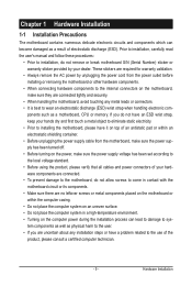
... Always turn on the computer if the CPU cooler is not installed, otherwise overheating and dam- It is not recommended that the motherboard supports the CPU. (Go to GIGABYTE's website for the peripherals. Hardware Installation 1-3 Installing the CPU and CPU Cooler Read the following guidelines before installing the CPU to prevent...keys on the CPU socket.) • Apply an even and thin layer of thermal grease on the CPU. Locate the alignment keys on the motherboard CPU socket and the notches on the surface of the CPU. • Do not turn off the computer and unplug the power cord from...
... Always turn on the computer if the CPU cooler is not installed, otherwise overheating and dam- It is not recommended that the motherboard supports the CPU. (Go to GIGABYTE's website for the peripherals. Hardware Installation 1-3 Installing the CPU and CPU Cooler Read the following guidelines before installing the CPU to prevent...keys on the CPU socket.) • Apply an even and thin layer of thermal grease on the CPU. Locate the alignment keys on the motherboard CPU socket and the notches on the surface of the CPU. • Do not turn off the computer and unplug the power cord from...

Manual
Page 14
... the rear grip of the socket cover and use your thumb to lift up the front edge (next to correctly install the CPU into the motherboard CPU socket. Hold your index finger down and away from the power outlet to prevent damage to the CPU. When replacing the load plate, make...
... the rear grip of the socket cover and use your thumb to lift up the front edge (next to correctly install the CPU into the motherboard CPU socket. Hold your index finger down and away from the power outlet to prevent damage to the CPU. When replacing the load plate, make...

Manual
Page 15
... sign on the male push pin. (Turning the push pin along the direction of the CPU cooler to the CPU fan header (CPU_FAN) on the motherboard. Step 4: You should hear a "click" when pushing down on installing the cooler.) Step 5: After the installation, check the back of the installed ...cooler and CPU may damage the CPU. - 15 - 1-3-2 Installing the CPU Cooler Follow the steps below to correctly install the CPU cooler on the motherboard. (The following procedure uses Intel® boxed cooler as the picture above shows, the installation is to install.) Step 3: Place the cooler atop ...
... sign on the male push pin. (Turning the push pin along the direction of the CPU cooler to the CPU fan header (CPU_FAN) on the motherboard. Step 4: You should hear a "click" when pushing down on installing the cooler.) Step 5: After the installation, check the back of the installed ...cooler and CPU may damage the CPU. - 15 - 1-3-2 Installing the CPU Cooler Follow the steps below to correctly install the CPU cooler on the motherboard. (The following procedure uses Intel® boxed cooler as the picture above shows, the installation is to install.) Step 3: Place the cooler atop ...

Manual
Page 16
..., DDR3_4 Dual Channel Memory Configurations Table DDR3_2 DDR3_1 DDR3_4 DDR3_3 Two Modules - - If only one DDR3 memory module is recommended that the motherboard supports the memory. Dual Channel mode cannot be sure to install the memory: • Make sure that memory of the memory. Hardware ... with two or four memory modules, it in the DDR3_1 or DDR3_3 socket. A memory module can be used . (Go to GIGABYTE's website for optimum performance. Enabling Dual Channel memory mode will automatically detect the specifications and capacity of the same capacity, brand, speed...
..., DDR3_4 Dual Channel Memory Configurations Table DDR3_2 DDR3_1 DDR3_4 DDR3_3 Two Modules - - If only one DDR3 memory module is recommended that the motherboard supports the memory. Dual Channel mode cannot be sure to install the memory: • Make sure that memory of the memory. Hardware ... with two or four memory modules, it in the DDR3_1 or DDR3_3 socket. A memory module can be used . (Go to GIGABYTE's website for optimum performance. Enabling Dual Channel memory mode will automatically detect the specifications and capacity of the same capacity, brand, speed...

Manual
Page 17
..., make sure to turn off the computer and unplug the power cord from the power outlet to prevent damage to install DDR3 DIMMs on this motherboard. Follow the steps below to correctly install your fingers on the socket. Place the memory module on the top edge of the memory module. Step...
..., make sure to turn off the computer and unplug the power cord from the power outlet to prevent damage to install DDR3 DIMMs on this motherboard. Follow the steps below to correctly install your fingers on the socket. Place the memory module on the top edge of the memory module. Step...

Manual
Page 18
...(s). 7. Hardware Installation - 18 - 1-5 Installing an Expansion Card Read the following guidelines before installing an expansion card to install an expansion card: • Make sure the motherboard supports the expansion card. Make sure the card is fully inserted into the slot. 4. Align the card with your card. Carefully read the manual that...
...(s). 7. Hardware Installation - 18 - 1-5 Installing an Expansion Card Read the following guidelines before installing an expansion card to install an expansion card: • Make sure the motherboard supports the expansion card. Make sure the card is fully inserted into the slot. 4. Align the card with your card. Carefully read the manual that...

Manual
Page 21
...3Gb/s Port The eSATA 3Gb/s port conforms to SATA 3Gb/s standard and is occurring Center/Subwoofer Speaker Out Jack (Orange) Use this port for GA-H55M-UD2H - 21 - Microphones must be connected to connect center/subwoofer speakers in a 4/5.1/7.1-channel audio configuration. The following describes the states of the LAN... removing the cable connected to a back panel connector, first remove the cable from your device and then remove it from the motherboard. • When removing the cable, pull it side to side to connect rear speakers in a 5.1/7.1-channel audio configuration.
...3Gb/s Port The eSATA 3Gb/s port conforms to SATA 3Gb/s standard and is occurring Center/Subwoofer Speaker Out Jack (Orange) Use this port for GA-H55M-UD2H - 21 - Microphones must be connected to connect center/subwoofer speakers in a 4/5.1/7.1-channel audio configuration. The following describes the states of the LAN... removing the cable connected to a back panel connector, first remove the cable from your device and then remove it from the motherboard. • When removing the cable, pull it side to side to connect rear speakers in a 5.1/7.1-channel audio configuration.

Manual
Page 22
... and your devices are compliant with the connectors you wish to connect. • Before installing the devices, be sure to the connector on the motherboard. j Only for GA-H55M-UD2H Hardware Installation - 22 - 1-7 Internal Connectors 1 18 2 3 10 8 6 5 13 17 12 7 9 11 4 16 15j 14 1) ATX_12V 2) ATX 3) CPU_FAN 4) SYS_FAN 5) FDD 6) IDE 7) SATA2_0/1/2/3/4 8) BAT 9) F_PANEL 10...
... and your devices are compliant with the connectors you wish to connect. • Before installing the devices, be sure to the connector on the motherboard. j Only for GA-H55M-UD2H Hardware Installation - 22 - 1-7 Internal Connectors 1 18 2 3 10 8 6 5 13 17 12 7 9 11 4 16 15j 14 1) ATX_12V 2) ATX 3) CPU_FAN 4) SYS_FAN 5) FDD 6) IDE 7) SATA2_0/1/2/3/4 8) BAT 9) F_PANEL 10...

Manual
Page 23
...or greater). Hardware Installation Connect the power supply cable to the CPU. If a power supply is turned off and all the components on the motherboard. The power connector possesses a foolproof design. Do not insert the power supply cable into pins under the protective cover when using a 2x12 ...power supply, remove the protective cover from the main power connector on the motherboard. 1/2) ATX_12V/ATX (2x2 12V Power Connector and 2x12 Main Power Connector) With the use of the power connector, the power supply can...
...or greater). Hardware Installation Connect the power supply cable to the CPU. If a power supply is turned off and all the components on the motherboard. The power connector possesses a foolproof design. Do not insert the power supply cable into pins under the protective cover when using a 2x12 ...power supply, remove the protective cover from the main power connector on the motherboard. 1/2) ATX_12V/ATX (2x2 12V Power Connector and 2x12 Main Power Connector) With the use of the power connector, the power supply can...
Manual
Page 24
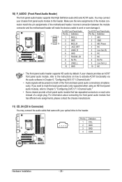
The motherboard supports CPU fan speed control, which requires the use of different color. Before connecting a floppy disk drive, be installed inside the chassis. 1 CPU_FAN 1 SYS_FAN CPU_FAN: ... 2.88 MB. Most fan headers possess a foolproof insertion design. The types of the connector and the floppy disk drive cable. 3/4) CPU_FAN/SYS_FAN (Fan Headers) The motherboard has a 4-pin CPU fan header (CPU_FAN) and a 4-pin system fan header (SYS_FAN). For purchasing the optional floppy disk drive cable, please contact the local dealer...
The motherboard supports CPU fan speed control, which requires the use of different color. Before connecting a floppy disk drive, be installed inside the chassis. 1 CPU_FAN 1 SYS_FAN CPU_FAN: ... 2.88 MB. Most fan headers possess a foolproof insertion design. The types of the connector and the floppy disk drive cable. 3/4) CPU_FAN/SYS_FAN (Fan Headers) The motherboard has a 4-pin CPU fan header (CPU_FAN) and a 4-pin system fan header (SYS_FAN). For purchasing the optional floppy disk drive cable, please contact the local dealer...
Manual
Page 28
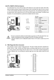
...an HD front panel audio module), refer to work or even damage it. Pin No. Incorrect connection between the module connector and the motherboard header will make the device unable to Chapter 5, "Configuring 2/4/5.1/7.1-Channel Audio." • Some chassis provide a front panel audio module that... In Connector) You may connect your chassis provides an AC'97 front panel audio module, refer to the instructions on each wire instead of the motherboard header. Definition 1 CD-L 1 2 GND 3 GND 4 CD-R Hardware Installation - 28 - Make sure the wire assignments of the module connector...
...an HD front panel audio module), refer to work or even damage it. Pin No. Incorrect connection between the module connector and the motherboard header will make the device unable to Chapter 5, "Configuring 2/4/5.1/7.1-Channel Audio." • Some chassis provide a front panel audio module that... In Connector) You may connect your chassis provides an AC'97 front panel audio module, refer to the instructions on each wire instead of the motherboard header. Definition 1 CD-L 1 2 GND 3 GND 4 CD-R Hardware Installation - 28 - Make sure the wire assignments of the module connector...

Manual
Page 29
... the HDMI display at the same time. For example, some graphics cards may require you to use a S/PDIF digital audio cable for your motherboard to an audio device that supports digital audio out via an optional S/PDIF In cable. 12) SPDIF_I (S/PDIF In Header) This header supports digital... contact the local dealer. For information about connecting the S/PDIF digital audio cable, carefully read the manual for digital audio output from your motherboard to your graphics card if you wish to connect an HDMI display to the graphics card and have digital audio output from your expansion card...
... the HDMI display at the same time. For example, some graphics cards may require you to use a S/PDIF digital audio cable for your motherboard to an audio device that supports digital audio out via an optional S/PDIF In cable. 12) SPDIF_I (S/PDIF In Header) This header supports digital... contact the local dealer. For information about connecting the S/PDIF digital audio cable, carefully read the manual for digital audio output from your motherboard to your graphics card if you wish to connect an HDMI display to the graphics card and have digital audio output from your expansion card...


