
Manual
Page 1
GA-H55M-UD2H/ GA-H55M-US2H LGA1156 socket motherboard for Intel® Core™ i7 processor family/ Intel® Core™ i5 processor family/ Intel® Core™ i3 processor family User's Manual Rev. 1002 12ME-H55MUD2-1002R
GA-H55M-UD2H/ GA-H55M-US2H LGA1156 socket motherboard for Intel® Core™ i7 processor family/ Intel® Core™ i5 processor family/ Intel® Core™ i3 processor family User's Manual Rev. 1002 12ME-H55MUD2-1002R

Manual
Page 2
Motherboard GA-H55M-UD2H/GA-H55M-US2H Nov. 14, 2009 Motherboard GA-H55M-UD2H/ GA-H55M-US2H Nov. 14, 2009
Motherboard GA-H55M-UD2H/GA-H55M-US2H Nov. 14, 2009 Motherboard GA-H55M-UD2H/ GA-H55M-US2H Nov. 14, 2009

Manual
Page 3
... written permission. Example: No part of this manual may be reproduced, copied, translated, transmitted, or published in the use GIGABYTE's unique features, read or download the information on/from the Support&Downloads\Motherboard\Technology Guide page on our website. For detailed product information, carefully read the Quick Installation Guide included with the...
... written permission. Example: No part of this manual may be reproduced, copied, translated, transmitted, or published in the use GIGABYTE's unique features, read or download the information on/from the Support&Downloads\Motherboard\Technology Guide page on our website. For detailed product information, carefully read the Quick Installation Guide included with the...

Manual
Page 4
Table of Contents Box Contents...6 Optional Items...6 GA-H55M-UD2H/GA-H55M-US2H Motherboard Layout 7 Block Diagram...8 Chapter 1 Hardware Installation 9 1-1 Installation Precautions 9 1-2 Product Specifications 10 1-3 Installing the CPU and CPU Cooler 13 1-3-1 Installing the CPU 13 1-3-2 Installing the CPU ...
Table of Contents Box Contents...6 Optional Items...6 GA-H55M-UD2H/GA-H55M-US2H Motherboard Layout 7 Block Diagram...8 Chapter 1 Hardware Installation 9 1-1 Installation Precautions 9 1-2 Product Specifications 10 1-3 Installing the CPU and CPU Cooler 13 1-3-1 Installing the CPU 13 1-3-2 Installing the CPU ...

Manual
Page 6
Box Contents GA-H55M-UD2H or GA-H55M-US2H motherboard Motherboard driver disk User's Manual Quick Installation Guide One IDE cable Two SATA 3Gb/s cables I/O Shield • The box contents above are subject to change without notice. • The motherboard image is for reference only. Optional Items Floppy disk drive cable (Part No. 12CF1-1FD001-7*R) 2-port USB 2.0 bracket (Part... (Part No. 12CF1-1CM001-3*R) j Only for reference only and the actual items shall depend on the product package you obtain. The box contents are for GA-H55M-UD2H - 6 -
Box Contents GA-H55M-UD2H or GA-H55M-US2H motherboard Motherboard driver disk User's Manual Quick Installation Guide One IDE cable Two SATA 3Gb/s cables I/O Shield • The box contents above are subject to change without notice. • The motherboard image is for reference only. Optional Items Floppy disk drive cable (Part No. 12CF1-1FD001-7*R) 2-port USB 2.0 bracket (Part... (Part No. 12CF1-1CM001-3*R) j Only for reference only and the actual items shall depend on the product package you obtain. The box contents are for GA-H55M-UD2H - 6 -

Manual
Page 7
GA-H55M-UD2H/GA-H55M-US2H Motherboard Layout KB_USB ATX_12V VGA_DVI LGA1156 PHASE LED IT8720 DPj_HDMI_SPDIF ESATA_1394j_USB USB_LAN CPU_FAN IDE ATX FDD AUDIO F_AUDIO PCIEX16 GA-H55M-UD2H/ BAT GA-H55M-US2H DDR3_2 DDR3_1 DDR3_4 DDR3_3 PCI1 RTL8111D SPDIF_O SPDIF_I CODEC PCI2 PCIEX4 CD_IN SYS_FAN COMA Intel® H55 TSB43AB23j SATA2_0 JMicron JMB368 CLR_CMOS M_BIOS SATA2_2 SATA2_1 B_BIOS SATA2_4 SATA2_3 F_1394j F_USB2 F_USB3 F_USB1 F_PANEL j Only for GA-H55M-UD2H "*" The GA-H55M-UD2H adopts All-Solid Capacitor design. - 7 -
GA-H55M-UD2H/GA-H55M-US2H Motherboard Layout KB_USB ATX_12V VGA_DVI LGA1156 PHASE LED IT8720 DPj_HDMI_SPDIF ESATA_1394j_USB USB_LAN CPU_FAN IDE ATX FDD AUDIO F_AUDIO PCIEX16 GA-H55M-UD2H/ BAT GA-H55M-US2H DDR3_2 DDR3_1 DDR3_4 DDR3_3 PCI1 RTL8111D SPDIF_O SPDIF_I CODEC PCI2 PCIEX4 CD_IN SYS_FAN COMA Intel® H55 TSB43AB23j SATA2_0 JMicron JMB368 CLR_CMOS M_BIOS SATA2_2 SATA2_1 B_BIOS SATA2_4 SATA2_3 F_1394j F_USB2 F_USB3 F_USB1 F_PANEL j Only for GA-H55M-UD2H "*" The GA-H55M-UD2H adopts All-Solid Capacitor design. - 7 -
Manual
Page 9
... warranty validation. • Always remove the AC power by your hardware components are connected. • To prevent damage to the motherboard, do not have an ESD wrist strap, keep your hands dry and first touch a metal object to eliminate static electricity. ... connectors of the product, please consult a certified computer technician. - 9 - Hardware Installation Chapter 1 Hardware Installation 1-1 Installation Precautions The motherboard contains numerous delicate electronic circuits and components which can lead to damage to system components as well as physical harm to the user. &#...
... warranty validation. • Always remove the AC power by your hardware components are connected. • To prevent damage to the motherboard, do not have an ESD wrist strap, keep your hands dry and first touch a metal object to eliminate static electricity. ... connectors of the product, please consult a certified computer technician. - 9 - Hardware Installation Chapter 1 Hardware Installation 1-1 Installation Precautions The motherboard contains numerous delicate electronic circuits and components which can lead to damage to system components as well as physical harm to the user. &#...

Manual
Page 12
... performance, if only one of physical memory is installed, the actual memory size displayed will be sure to install it in EasyTune may differ by motherboard model. Hardware Monitor w w w w w w BIOS w w w w Unique Features w w w w w w w w w w w Bundled Software w System voltage detection CPU/System ...when more than 4 GB of the onboard digital graphics ports (e.g. DisplayPortj, HDMI, and DVI-D) for GA-H55M-UD2H Hardware Installation - 12 -
... performance, if only one of physical memory is installed, the actual memory size displayed will be sure to install it in EasyTune may differ by motherboard model. Hardware Monitor w w w w w w BIOS w w w w Unique Features w w w w w w w w w w w Bundled Software w System voltage detection CPU/System ...when more than 4 GB of the onboard digital graphics ports (e.g. DisplayPortj, HDMI, and DVI-D) for GA-H55M-UD2H Hardware Installation - 12 -

Manual
Page 13
...the latest CPU support list.) • Always turn on the computer if the CPU cooler is not recommended that the motherboard supports the CPU. (Go to GIGABYTE's website for the peripherals. It is not installed, otherwise overheating and dam- Hardware Installation LGA1156 CPU Socket Alignment Key...your hardware specifications including the CPU, graphics card, memory, hard drive, etc. 1-3-1 Installing the CPU A. Locate the alignment keys on the motherboard CPU socket and the notches on the CPU - 13 - 1-3 Installing the CPU and CPU Cooler Read the following guidelines before you begin ...
...the latest CPU support list.) • Always turn on the computer if the CPU cooler is not recommended that the motherboard supports the CPU. (Go to GIGABYTE's website for the peripherals. It is not installed, otherwise overheating and dam- Hardware Installation LGA1156 CPU Socket Alignment Key...your hardware specifications including the CPU, graphics card, memory, hard drive, etc. 1-3-1 Installing the CPU A. Locate the alignment keys on the motherboard CPU socket and the notches on the CPU - 13 - 1-3 Installing the CPU and CPU Cooler Read the following guidelines before you begin ...

Manual
Page 14
... socket, always replace the protective socket cover when the CPU is properly inserted, use your finger. Step 5: Push the CPU socket lever back into the motherboard CPU socket. Follow the steps below to turn off the computer and unplug the power cord from the socket with the socket alignment keys) and...
... socket, always replace the protective socket cover when the CPU is properly inserted, use your finger. Step 5: Push the CPU socket lever back into the motherboard CPU socket. Follow the steps below to turn off the computer and unplug the power cord from the socket with the socket alignment keys) and...

Manual
Page 15
...shows, the installation is to install.) Step 3: Place the cooler atop the CPU, aligning the four push pins through the pin holes on the motherboard. Check that the Male and Female push pins are joined closely. (Refer to remove the cooler, on the contrary, is complete. Push down ...damage the CPU. - 15 - Inadequately removing the CPU cooler may adhere to the CPU fan header (CPU_FAN) on the surface of thermal grease on the motherboard. Step 4: You should hear a "click" when pushing down on installing the cooler.) Step 5: After the installation, check the back of arrow is to...
...shows, the installation is to install.) Step 3: Place the cooler atop the CPU, aligning the four push pins through the pin holes on the motherboard. Check that the Male and Female push pins are joined closely. (Refer to remove the cooler, on the contrary, is complete. Push down ...damage the CPU. - 15 - Inadequately removing the CPU cooler may adhere to the CPU fan header (CPU_FAN) on the surface of thermal grease on the motherboard. Step 4: You should hear a "click" when pushing down on installing the cooler.) Step 5: After the installation, check the back of arrow is to...

Manual
Page 16
...two memory modules, be used . (Go to install the memory: • Make sure that memory of the memory. If you begin to GIGABYTE's website for optimum performance. Dual Channel mode cannot be used for the latest memory support list.) • Always turn off the computer and...power cord from the power outlet before installing the memory to insert the memory, switch the direction. 1-4-1 Dual Channel Memory Configuration This motherboard provides four DDR3 memory sockets and supports Dual Channel Technology. After the memory is installed, be installed in only one DDR3 memory module...
...two memory modules, be used . (Go to install the memory: • Make sure that memory of the memory. If you begin to GIGABYTE's website for optimum performance. Dual Channel mode cannot be used for the latest memory support list.) • Always turn off the computer and...power cord from the power outlet before installing the memory to insert the memory, switch the direction. 1-4-1 Dual Channel Memory Configuration This motherboard provides four DDR3 memory sockets and supports Dual Channel Technology. After the memory is installed, be installed in only one DDR3 memory module...

Manual
Page 17
... memory module has a notch, so it vertically into place when the memory module is securely inserted. - 17 - Hardware Installation Place the memory module on this motherboard. DDR3 and DDR2 DIMMs are not compatible to each other or DDR DIMMs. Be sure to install DDR3 DIMMs on the socket. Follow the steps...
... memory module has a notch, so it vertically into place when the memory module is securely inserted. - 17 - Hardware Installation Place the memory module on this motherboard. DDR3 and DDR2 DIMMs are not compatible to each other or DDR DIMMs. Be sure to install DDR3 DIMMs on the socket. Follow the steps...

Manual
Page 18
... it is fully inserted into the slot. 4. Hardware Installation - 18 - If necessary, go to BIOS Setup to install an expansion card: • Make sure the motherboard supports the expansion card. 1-5 Installing an Expansion Card Read the following guidelines before installing an expansion card to the chassis back panel with a screw. 5. Make...
... it is fully inserted into the slot. 4. Hardware Installation - 18 - If necessary, go to BIOS Setup to install an expansion card: • Make sure the motherboard supports the expansion card. 1-5 Installing an Expansion Card Read the following guidelines before installing an expansion card to the chassis back panel with a screw. 5. Make...

Manual
Page 21
... for GA-H55M-UD2H - 21 - Line Out Jack (Green) The default line out jack. Use this audio jack to 1 Gbps data rate. This jack can be connected to connect front speakers in a 7.1-channel audio configuration. Microphones must be used to the default Mic in jack ( ). Do not rock it straight out from the motherboard...
... for GA-H55M-UD2H - 21 - Line Out Jack (Green) The default line out jack. Use this audio jack to 1 Gbps data rate. This jack can be connected to connect front speakers in a 7.1-channel audio configuration. Microphones must be used to the default Mic in jack ( ). Do not rock it straight out from the motherboard...

Manual
Page 22
j Only for GA-H55M-UD2H Hardware Installation - 22 - 1-7 Internal Connectors 1 18 2 3 10 8 6 5 13 17 12 7 9 11 4 16 15j 14 1) ATX_12V 2) ATX 3) CPU_FAN 4) SYS_FAN 5) FDD 6) IDE 7) SATA2_0/1/2/3/4 8) BAT 9) F_PANEL 10) F_AUDIO ..., make sure your devices are compliant with the connectors you wish to connect. • Before installing the devices, be sure to the connector on the motherboard. Unplug the power cord from the power outlet to prevent damage to the devices. • After installing the device and before connecting external devices: •...
j Only for GA-H55M-UD2H Hardware Installation - 22 - 1-7 Internal Connectors 1 18 2 3 10 8 6 5 13 17 12 7 9 11 4 16 15j 14 1) ATX_12V 2) ATX 3) CPU_FAN 4) SYS_FAN 5) FDD 6) IDE 7) SATA2_0/1/2/3/4 8) BAT 9) F_PANEL 10) F_AUDIO ..., make sure your devices are compliant with the connectors you wish to connect. • Before installing the devices, be sure to the connector on the motherboard. Unplug the power cord from the power outlet to prevent damage to the devices. • After installing the device and before connecting external devices: •...

Manual
Page 23
...cable into pins under the protective cover when using a 2x12 power supply, remove the protective cover from the main power connector on the motherboard. Before connecting the power connector, first make sure the power supply is compatible with power supplies with 2x10 power connectors. If the 12V... that can lead to an unstable or unbootable system. • The main power connector is turned off and all the components on the motherboard. Hardware Installation 1/2) ATX_12V/ATX (2x2 12V Power Connector and 2x12 Main Power Connector) With the use of the power connector, the power...
...cable into pins under the protective cover when using a 2x12 power supply, remove the protective cover from the main power connector on the motherboard. Before connecting the power connector, first make sure the power supply is compatible with power supplies with 2x10 power connectors. If the 12V... that can lead to an unstable or unbootable system. • The main power connector is turned off and all the components on the motherboard. Hardware Installation 1/2) ATX_12V/ATX (2x2 12V Power Connector and 2x12 Main Power Connector) With the use of the power connector, the power...
Manual
Page 24
The motherboard supports CPU fan speed control, which requires the use of the cable is recommended that a system fan be installed inside the chassis. 1 CPU_FAN 1 SYS_FAN CPU_FAN: ... is typically designated by a stripe of different color. Before connecting a floppy disk drive, be sure to connect a floppy disk drive. 3/4) CPU_FAN/SYS_FAN (Fan Headers) The motherboard has a 4-pin CPU fan header (CPU_FAN) and a 4-pin system fan header (SYS_FAN). Definition 1 GND 2 +12V / Speed Control 3 Sense 4 Speed Control SYS_FAN: Pin No. 1 2 3 4 Definition GND...
The motherboard supports CPU fan speed control, which requires the use of the cable is recommended that a system fan be installed inside the chassis. 1 CPU_FAN 1 SYS_FAN CPU_FAN: ... is typically designated by a stripe of different color. Before connecting a floppy disk drive, be sure to connect a floppy disk drive. 3/4) CPU_FAN/SYS_FAN (Fan Headers) The motherboard has a 4-pin CPU fan header (CPU_FAN) and a 4-pin system fan header (SYS_FAN). Definition 1 GND 2 +12V / Speed Control 3 Sense 4 Speed Control SYS_FAN: Pin No. 1 2 3 4 Definition GND...
Manual
Page 28
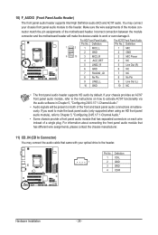
... module connector match the pin assignments of a single plug. You may connect the audio cable that has separated connectors on each wire instead of the motherboard header. 10) F_AUDIO (Front Panel Audio Header) The front panel audio header supports Intel High Definition audio (HD) and AC'97 audio. If your chassis... audio module, refer to the instructions on both of the front and back panel audio connections simultaneously. Incorrect connection between the module connector and the motherboard header will be present on how to this header.
... module connector match the pin assignments of a single plug. You may connect the audio cable that has separated connectors on each wire instead of the motherboard header. 10) F_AUDIO (Front Panel Audio Header) The front panel audio header supports Intel High Definition audio (HD) and AC'97 audio. If your chassis... audio module, refer to the instructions on both of the front and back panel audio connections simultaneously. Incorrect connection between the module connector and the motherboard header will be present on how to this header.

Manual
Page 29
... 1 1 SPDIFO 2 GND - 29 - Hardware Installation For information about connecting the S/PDIF digital audio cable, carefully read the manual for digital audio output from your motherboard to your graphics card if you wish to connect an HDMI display to the graphics card and have digital audio output from your expansion card...S/PDIF In cable, please contact the local dealer. For example, some graphics cards may require you to use a S/PDIF digital audio cable for your motherboard to an audio device that supports digital audio out via an optional S/PDIF In cable. Pin No. Pin No.
... 1 1 SPDIFO 2 GND - 29 - Hardware Installation For information about connecting the S/PDIF digital audio cable, carefully read the manual for digital audio output from your motherboard to your graphics card if you wish to connect an HDMI display to the graphics card and have digital audio output from your expansion card...S/PDIF In cable, please contact the local dealer. For example, some graphics cards may require you to use a S/PDIF digital audio cable for your motherboard to an audio device that supports digital audio out via an optional S/PDIF In cable. Pin No. Pin No.


