Manual
Page 1
GA-H55-USB3 LGA1156 socket motherboard for Intel® Core™ i7 processor family/ Intel® Core™ i5 processor family/ Intel® Core™ i3 processor family User's Manual Rev. 1001 12ME-H55USB3-1001R
GA-H55-USB3 LGA1156 socket motherboard for Intel® Core™ i7 processor family/ Intel® Core™ i5 processor family/ Intel® Core™ i3 processor family User's Manual Rev. 1001 12ME-H55USB3-1001R
Manual
Page 2
Motherboard GA-H55-USB3 Feb. 5, 2010 Motherboard GA-H55-USB3 Feb. 5, 2010
Motherboard GA-H55-USB3 Feb. 5, 2010 Motherboard GA-H55-USB3 Feb. 5, 2010
Manual
Page 3
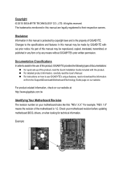
... this manual is 1.0. For instructions on how to the specifications and features in the use GIGABYTE's unique features, read or download the information on/from the Support&Downloads\Motherboard\Technology Guide page on your motherboard revision before updating motherboard BIOS, drivers, or when looking for technical information. Documentation Classifications In order to their respective...
... this manual is 1.0. For instructions on how to the specifications and features in the use GIGABYTE's unique features, read or download the information on/from the Support&Downloads\Motherboard\Technology Guide page on your motherboard revision before updating motherboard BIOS, drivers, or when looking for technical information. Documentation Classifications In order to their respective...
Manual
Page 4
Table of Contents Box Contents...6 Optional Items...6 GA-H55-USB3 Motherboard Layout 7 GA-H55-USB3 Motherboard Block Diagram 8 Chapter 1 Hardware Installation 9 1-1 Installation Precautions 9 1-2 Product Specifications 10 1-3 Installing the CPU and CPU Cooler 13 1-3-1 Installing the CPU 13 1-3-2 Installing the CPU Cooler ...
Table of Contents Box Contents...6 Optional Items...6 GA-H55-USB3 Motherboard Layout 7 GA-H55-USB3 Motherboard Block Diagram 8 Chapter 1 Hardware Installation 9 1-1 Installation Precautions 9 1-2 Product Specifications 10 1-3 Installing the CPU and CPU Cooler 13 1-3-1 Installing the CPU 13 1-3-2 Installing the CPU Cooler ...
Manual
Page 6
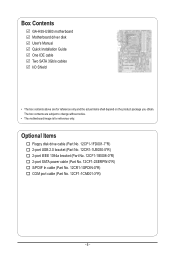
Box Contents GA-H55-USB3 motherboard Motherboard driver disk User's Manual Quick Installation Guide One IDE cable Two SATA 3Gb/s cables I/O Shield • The box contents above are subject to change without notice. • The motherboard image is for reference only and the actual items shall depend on the product package you obtain. Optional Items Floppy disk...
Box Contents GA-H55-USB3 motherboard Motherboard driver disk User's Manual Quick Installation Guide One IDE cable Two SATA 3Gb/s cables I/O Shield • The box contents above are subject to change without notice. • The motherboard image is for reference only and the actual items shall depend on the product package you obtain. Optional Items Floppy disk...
Manual
Page 7
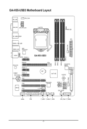
GA-H55-USB3 Motherboard Layout KB_USB CPU_FAN VGA_DVI ATX_12V_2X4 LGA1156 PHASE LED DP_HDMI_SPDIF ESATA_1394_USB USB30_LAN NEC D720200F1 AUDIO F_AUDIO PCIEX1_1 RTL8111D PCIEX16 PCIEX1_2 PCI2 CODEC PCIEX1_3 SPDIF_O CD_IN PCI1 SPDIF_I PCI2 IT8720 PCI3 ATX PWR_FAN GA-H55-USB3 DDR3_2 DDR3_1 DDR3_4 DDR3_3 GIGABYTE SATA2 GSATA2_6 GSATA2_5 BAT Intel® H55 M_BIOS B_BIOS SYS_FAN2 TSB43AB23 F_1394 SATA2_3 SATA2_0 SATA2_4 SATA2_1 SATA2_2 CLR_CMOS IDE COMA FDD F_USB1 F_USB2 F_USB3 SYS_FAN1 F_PANEL - 7 -
GA-H55-USB3 Motherboard Layout KB_USB CPU_FAN VGA_DVI ATX_12V_2X4 LGA1156 PHASE LED DP_HDMI_SPDIF ESATA_1394_USB USB30_LAN NEC D720200F1 AUDIO F_AUDIO PCIEX1_1 RTL8111D PCIEX16 PCIEX1_2 PCI2 CODEC PCIEX1_3 SPDIF_O CD_IN PCI1 SPDIF_I PCI2 IT8720 PCI3 ATX PWR_FAN GA-H55-USB3 DDR3_2 DDR3_1 DDR3_4 DDR3_3 GIGABYTE SATA2 GSATA2_6 GSATA2_5 BAT Intel® H55 M_BIOS B_BIOS SYS_FAN2 TSB43AB23 F_1394 SATA2_3 SATA2_0 SATA2_4 SATA2_1 SATA2_2 CLR_CMOS IDE COMA FDD F_USB1 F_USB2 F_USB3 SYS_FAN1 F_PANEL - 7 -
Manual
Page 8
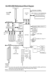
...GA-H55-USB3 Motherboard Block Diagram 1 PCI Express x16 CPU CLK+/- (133 MHz) PCIe CLK (100 MHz) LGA1156 CPU DDR3 1666 (O.C.)/1333/1066/800 MHz Dual Channel Memory DMI Interface FDI Interface PCI Express Bus LAN RJ45 x16 x1 Gen 2 2 USB 3.0 RTL8111D Switch x1 Gen 1 NEC D720200F1 PCI Express X1 X1 X1 Bus x1 GIGABYTE... SATA2 Intel® H55 3 PCI Express x1 2 SATA 3Gb/s PCI Bus ATA-133/100/66/33 IDE Channel TSB43AB23 2 IEEE 1394a CODEC DisplayPort, HDMI, ...
...GA-H55-USB3 Motherboard Block Diagram 1 PCI Express x16 CPU CLK+/- (133 MHz) PCIe CLK (100 MHz) LGA1156 CPU DDR3 1666 (O.C.)/1333/1066/800 MHz Dual Channel Memory DMI Interface FDI Interface PCI Express Bus LAN RJ45 x16 x1 Gen 2 2 USB 3.0 RTL8111D Switch x1 Gen 1 NEC D720200F1 PCI Express X1 X1 X1 Bus x1 GIGABYTE... SATA2 Intel® H55 3 PCI Express x1 2 SATA 3Gb/s PCI Bus ATA-133/100/66/33 IDE Channel TSB43AB23 2 IEEE 1394a CODEC DisplayPort, HDMI, ...

Manual
Page 9
...warranty validation. • Always remove the AC power by your hardware components are connected tightly and securely. • When handling the motherboard, avoid touching any installation steps or have a problem related to the use of the product, please consult a certified computer technician.... - 9 - Chapter 1 Hardware Installation 1-1 Installation Precautions The motherboard contains numerous delicate electronic circuits and components which can lead to damage to system components as well as physical harm to the user...
...warranty validation. • Always remove the AC power by your hardware components are connected tightly and securely. • When handling the motherboard, avoid touching any installation steps or have a problem related to the use of the product, please consult a certified computer technician.... - 9 - Chapter 1 Hardware Installation 1-1 Installation Precautions The motherboard contains numerous delicate electronic circuits and components which can lead to damage to system components as well as physical harm to the user...

Manual
Page 12
... or when during the POST screens. (Note 5) Two share the same ports with integrated graphics. (Note 3) The DVI-D port does not support D-Sub connection by motherboard model. Hardware Installation - 12 - DisplayPort, HDMI, and DVI-D) for Microsoft® Windows® 7/Vista/XP Form Factor w ATX Form Factor; 30.5cm x 24.4cm (Note...
... or when during the POST screens. (Note 5) Two share the same ports with integrated graphics. (Note 3) The DVI-D port does not support D-Sub connection by motherboard model. Hardware Installation - 12 - DisplayPort, HDMI, and DVI-D) for Microsoft® Windows® 7/Vista/XP Form Factor w ATX Form Factor; 30.5cm x 24.4cm (Note...
Manual
Page 13
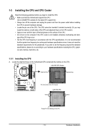
Hardware Installation Locate the alignment keys on the motherboard CPU socket and the notches on the CPU - 13 - It is not installed, otherwise overheating and dam- If you begin to install the CPU: • ... meet the standard requirements for the latest CPU support list.) • Always turn on the computer if the CPU cooler is not recommended that the motherboard supports the CPU. (Go to GIGABYTE's website for the peripherals.
Hardware Installation Locate the alignment keys on the motherboard CPU socket and the notches on the CPU - 13 - It is not installed, otherwise overheating and dam- If you begin to install the CPU: • ... meet the standard requirements for the latest CPU support list.) • Always turn on the computer if the CPU cooler is not recommended that the motherboard supports the CPU. (Go to GIGABYTE's website for the peripherals.

Manual
Page 14
... up the front edge (next to lightly replace the load plate. When replacing the load plate, make sure to correctly install the CPU into the motherboard CPU socket. Step 5: Push the CPU socket lever back into position. B. Follow the steps below to turn off the computer and unplug the power cord...
... up the front edge (next to lightly replace the load plate. When replacing the load plate, make sure to correctly install the CPU into the motherboard CPU socket. Step 5: Push the CPU socket lever back into position. B. Follow the steps below to turn off the computer and unplug the power cord...

Manual
Page 15
... check the back of the CPU cooler to the CPU fan header (CPU_FAN) on the motherboard. Hardware Installation 1-3-2 Installing the CPU Cooler Follow the steps below to correctly install the CPU cooler on the motherboard. (The following procedure uses Intel® boxed cooler as the picture above shows, the ...installation is to install.) Step 3: Place the cooler atop the CPU, aligning the four push pins through the pin holes on the motherboard. Direction of the Arrow Sign on the Male Push Pin Male Push Pin The Top of Female Push Pin Female Push Pin Step 2: Before ...
... check the back of the CPU cooler to the CPU fan header (CPU_FAN) on the motherboard. Hardware Installation 1-3-2 Installing the CPU Cooler Follow the steps below to correctly install the CPU cooler on the motherboard. (The following procedure uses Intel® boxed cooler as the picture above shows, the ...installation is to install.) Step 3: Place the cooler atop the CPU, aligning the four push pins through the pin holes on the motherboard. Direction of the Arrow Sign on the Male Push Pin Male Push Pin The Top of Female Push Pin Female Push Pin Step 2: Before ...
Manual
Page 16
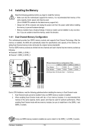
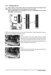
... Installation - 16 - The four DDR3 memory sockets are unable to insert the memory, switch the direction. 1-4-1 Dual Channel Memory Configuration This motherboard provides four DDR3 memory sockets and supports Dual Channel Technology. A memory module can be sure to install it is installed, the BIOS will double... Channel memory mode will automatically detect the specifications and capacity of the same capacity, brand, speed, and chips be used . (Go to GIGABYTE's website for optimum performance. Four Modules DS/SS DS/SS DS/SS DDR3_3 DS/SS DS/SS (SS=Single-Sided, DS=Double-Sided,...
... Installation - 16 - The four DDR3 memory sockets are unable to insert the memory, switch the direction. 1-4-1 Dual Channel Memory Configuration This motherboard provides four DDR3 memory sockets and supports Dual Channel Technology. A memory module can be sure to install it is installed, the BIOS will double... Channel memory mode will automatically detect the specifications and capacity of the same capacity, brand, speed, and chips be used . (Go to GIGABYTE's website for optimum performance. Four Modules DS/SS DS/SS DS/SS DDR3_3 DS/SS DS/SS (SS=Single-Sided, DS=Double-Sided,...
Manual
Page 17
... of the socket will snap into the memory socket. Hardware Installation Follow the steps below to the memory module. Place the memory module on this motherboard.
... of the socket will snap into the memory socket. Hardware Installation Follow the steps below to the memory module. Place the memory module on this motherboard.
Manual
Page 18
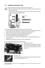
... the chassis back panel. 2. Remove the metal slot cover from the power outlet before you begin to install an expansion card: • Make sure the motherboard supports the expansion card. 1-5 Installing an Expansion Card Read the following guidelines before installing an expansion card to prevent hardware damage. Carefully read the manual...
... the chassis back panel. 2. Remove the metal slot cover from the power outlet before you begin to install an expansion card: • Make sure the motherboard supports the expansion card. 1-5 Installing an Expansion Card Read the following guidelines before installing an expansion card to prevent hardware damage. Carefully read the manual...

Manual
Page 21
... 2.0/1.1 specification. Only microphones still MUST be used to prevent an electrical short inside the cable connector. - 21 - Do not rock it straight out from the motherboard. • When removing the cable, pull it side to side to connect front speakers in a 7.1-channel audio configuration. USB 3.0/2.0 Port The USB 3.0 port supports the...
... 2.0/1.1 specification. Only microphones still MUST be used to prevent an electrical short inside the cable connector. - 21 - Do not rock it straight out from the motherboard. • When removing the cable, pull it side to side to connect front speakers in a 7.1-channel audio configuration. USB 3.0/2.0 Port The USB 3.0 port supports the...

Manual
Page 22
...) CD_IN 14) SPDIF_I 15) SPDIF_O 16) F_USB1/F_USB2/F_USB3 17) F_1394 18) COMA 19) CLR_CMOS 20) PHASE_LED Read the following guidelines before turning on the motherboard. Hardware Installation - 22 - Unplug the power cord from the power outlet to prevent damage to the devices. • After installing the device and before connecting...
...) CD_IN 14) SPDIF_I 15) SPDIF_O 16) F_USB1/F_USB2/F_USB3 17) F_1394 18) COMA 19) CLR_CMOS 20) PHASE_LED Read the following guidelines before turning on the motherboard. Hardware Installation - 22 - Unplug the power cord from the power outlet to prevent damage to the devices. • After installing the device and before connecting...

Manual
Page 23
... CPU manufacturer when using an Intel Extreme Edition CPU (130W). • To meet expansion requirements, it is turned off and all the components on the motherboard. If a power supply is used (500W or greater). The 12V power connector mainly supplies power to an unstable or unbootable system. 8 4 5 1 ATX_12V_2X4 ATX_12V_2X4: Pin No...
... CPU manufacturer when using an Intel Extreme Edition CPU (130W). • To meet expansion requirements, it is turned off and all the components on the motherboard. If a power supply is used (500W or greater). The 12V power connector mainly supplies power to an unstable or unbootable system. 8 4 5 1 ATX_12V_2X4 ATX_12V_2X4: Pin No...

Manual
Page 24
...CPU fan with fan speed control design. When connecting a fan cable, be sure to connect it is the ground wire). The motherboard supports CPU fan speed control, which requires the use of the connector and the floppy disk drive cable. The types of different ...1 GND 1 SYS_FAN2 2 +12V / Speed Control 3 Sense 4 Reserve 1 SYS_FAN1 1 PWR_FAN SYS_FAN1/PWR_FAN: Pin No. 3/4/5) CPU_FAN/SYS_FAN1/SYS_FAN2/PWR_FAN (Fan Headers) The motherboard has a 4-pin CPU fan header (CPU_FAN), a 4-pin (SYS_FAN2) and a 3-pin system fans, and a 3-pin power fan. Most fan headers possess a foolproof ...
...CPU fan with fan speed control design. When connecting a fan cable, be sure to connect it is the ground wire). The motherboard supports CPU fan speed control, which requires the use of the connector and the floppy disk drive cable. The types of different ...1 GND 1 SYS_FAN2 2 +12V / Speed Control 3 Sense 4 Reserve 1 SYS_FAN1 1 PWR_FAN SYS_FAN1/PWR_FAN: Pin No. 3/4/5) CPU_FAN/SYS_FAN1/SYS_FAN2/PWR_FAN (Fan Headers) The motherboard has a 4-pin CPU fan header (CPU_FAN), a 4-pin (SYS_FAN2) and a 3-pin system fans, and a 3-pin power fan. Most fan headers possess a foolproof ...

Manual
Page 28
... your optical drive to the instructions on each wire instead of a single plug. Incorrect connection between the module connector and the motherboard header will be present on both of the motherboard header. If your chassis front panel audio module to work or even damage it. Make sure the wire assignments of the...
... your optical drive to the instructions on each wire instead of a single plug. Incorrect connection between the module connector and the motherboard header will be present on both of the motherboard header. If your chassis front panel audio module to work or even damage it. Make sure the wire assignments of the...


