Manual
Page 3
...; For instructions on how to their respective owners. Example: The trademarks mentioned in this manual are legally registered to use GIGABYTE's unique features, read or download the information on/from the Support&Downloads\Motherboard\Technology Guide page on your motherboard revision before updating motherboard BIOS, drivers, or when looking for technical information...
...; For instructions on how to their respective owners. Example: The trademarks mentioned in this manual are legally registered to use GIGABYTE's unique features, read or download the information on/from the Support&Downloads\Motherboard\Technology Guide page on your motherboard revision before updating motherboard BIOS, drivers, or when looking for technical information...
Manual
Page 7
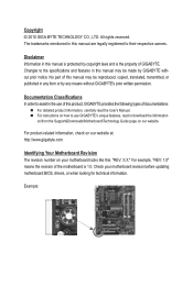
...™ 2 Duo processor/ Intel® Pentium® processor/Intel® Celeron® processor in the LGA775 package (Go to GIGABYTE's website for the latest CPU support list.) L2 cache varies with CPU Front Side Bus w 1333/1066/800 MHz FSB Chipset w w Memory w w... South Bridge: Intel® ICH7 2 x 1.5V DDR3 DIMM sockets supporting up to 4 GB of system memory Dual channel memory architecture Support for DDR3 1066/800 MHz memory modules (Go to GIGABYTE's website for the latest supported memory speeds and memory modules.) Integrated in the North Bridge: - ...
...™ 2 Duo processor/ Intel® Pentium® processor/Intel® Celeron® processor in the LGA775 package (Go to GIGABYTE's website for the latest CPU support list.) L2 cache varies with CPU Front Side Bus w 1333/1066/800 MHz FSB Chipset w w Memory w w... South Bridge: Intel® ICH7 2 x 1.5V DDR3 DIMM sockets supporting up to 4 GB of system memory Dual channel memory architecture Support for DDR3 1066/800 MHz memory modules (Go to GIGABYTE's website for the latest supported memory speeds and memory modules.) Integrated in the North Bridge: - ...
Manual
Page 8
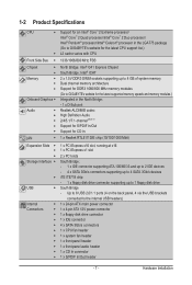
... DualBIOS™ PnP 1.0a, DMI 2.0, SM BIOS 2.4, ACPI 1.0b Support for @BIOS Support for Q-Flash Support for Xpress BIOS Rescue Support for Download Center Support for Xpress Install Support for Xpress Recovery2 Support for EasyTune (Note 3) Support for Easy Energy Saver (Note 4) Support for Time Repair Support for ON/OFF Charge Support for Q-Share Bundled Software w Norton Internet Security (OEM version...
... DualBIOS™ PnP 1.0a, DMI 2.0, SM BIOS 2.4, ACPI 1.0b Support for @BIOS Support for Q-Flash Support for Xpress BIOS Rescue Support for Download Center Support for Xpress Install Support for Xpress Recovery2 Support for EasyTune (Note 3) Support for Easy Energy Saver (Note 4) Support for Time Repair Support for ON/OFF Charge Support for Q-Share Bundled Software w Norton Internet Security (OEM version...
Manual
Page 9
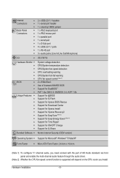
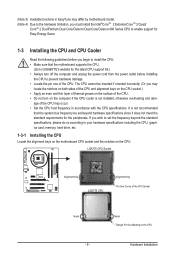
...and unplug the power cord from the power outlet before you begin to install the CPU: • Make sure that the motherboard supports the CPU. (Go to GIGABYTE's website for the peripherals. LGA775 CPU Socket Alignment Key LGA775 CPU Alignment Key Pin One Corner of the CPU Socket Notch - ...must install the Intel®CoreTM 2 Extreme/CoreTM 2 Quad/ CoreTM 2 Duo/Pentium Dual-Core/Celeron Dual-Core/Celeron 400 Series CPU to enable support for Easy Energy Saver. 1-3 Installing the CPU and CPU Cooler Read the following guidelines before installing the CPU to prevent hardware damage. •...
...and unplug the power cord from the power outlet before you begin to install the CPU: • Make sure that the motherboard supports the CPU. (Go to GIGABYTE's website for the peripherals. LGA775 CPU Socket Alignment Key LGA775 CPU Alignment Key Pin One Corner of the CPU Socket Notch - ...must install the Intel®CoreTM 2 Extreme/CoreTM 2 Quad/ CoreTM 2 Duo/Pentium Dual-Core/Celeron Dual-Core/Celeron 400 Series CPU to enable support for Easy Energy Saver. 1-3 Installing the CPU and CPU Cooler Read the following guidelines before installing the CPU to prevent hardware damage. •...
Manual
Page 10
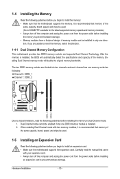
...Due to insert the memory, switch the direction. 1-4-1 Dual Channel Memory Configuration This motherboard provides two DDR3 memory sockets and supports Dual Channel Technology. 1-4 Installing the Memory Read the following guidelines before you begin to install an expansion card: • Make sure... Channel mode cannot be used . 1-5 Installing an Expansion Card Read the following guidelines before installing the memory to GIGABYTE's website for the latest supported memory speeds and memory modules.) • Always turn off the computer and unplug the power cord from the power...
...Due to insert the memory, switch the direction. 1-4-1 Dual Channel Memory Configuration This motherboard provides two DDR3 memory sockets and supports Dual Channel Technology. 1-4 Installing the Memory Read the following guidelines before you begin to install an expansion card: • Make sure... Channel mode cannot be used . 1-5 Installing an Expansion Card Read the following guidelines before installing the memory to GIGABYTE's website for the latest supported memory speeds and memory modules.) • Always turn off the computer and unplug the power cord from the power...
Manual
Page 11
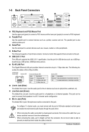
... and etc. To configure 7.1-channel audio, you need connect with the port of the LAN port LEDs. Hardware Installation D-Sub Port The D-Sub port supports a 15-pin D-Sub connector. Use this audio jack for a headphone or 2-channel speaker. Use this port for USB devices such as an optical ...cable, pull it side to side to this jack. Line Out Jack (Green) The default line out jack. USB 2.0/1.1 Port The USB port supports the USB 2.0/1.1 specification. The following describes the states of HD Audio standard via front panel and enable the multi-channel audio feature through the ...
... and etc. To configure 7.1-channel audio, you need connect with the port of the LAN port LEDs. Hardware Installation D-Sub Port The D-Sub port supports a 15-pin D-Sub connector. Use this audio jack for a headphone or 2-channel speaker. Use this port for USB devices such as an optical ...cable, pull it side to side to this jack. Line Out Jack (Green) The default line out jack. USB 2.0/1.1 Port The USB port supports the USB 2.0/1.1 specification. The following describes the states of HD Audio standard via front panel and enable the multi-channel audio feature through the ...
Manual
Page 14
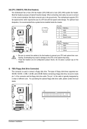
... the connector and the floppy disk drive cable. When connecting a fan cable, be sure to locate pin 1 of floppy disk drives supported are not configuration jumper blocks. Overheating may result in the correct orientation (the black connector wire is recommended that a system fan be ...FDD (Floppy Disk Drive Connector) This connector is typically designated by a stripe of a CPU fan with fan speed control design. The motherboard supports CPU fan speed control, which requires the use of different color. For optimum heat dissipation, it in damage to prevent your CPU and system ...
... the connector and the floppy disk drive cable. When connecting a fan cable, be sure to locate pin 1 of floppy disk drives supported are not configuration jumper blocks. Overheating may result in the correct orientation (the black connector wire is recommended that a system fan be ...FDD (Floppy Disk Drive Connector) This connector is typically designated by a stripe of a CPU fan with fan speed control design. The motherboard supports CPU fan speed control, which requires the use of different color. For optimum heat dissipation, it in damage to prevent your CPU and system ...
Manual
Page 15
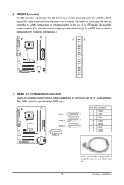
.../s standard. Definition 1 GND 1 2 TXP 3 TXN 1 4 GND 5 RXN 1 6 RXP 7 GND - 15 - Before attaching the IDE cable, locate the foolproof groove on the connector. Each SATA connector supports a single SATA device. Hardware Installation If you wish to connect two IDE devices, remember to set the jumpers and the cabling according to the role... of the SATA cable to two IDE devices such as hard drives and optical drives. 6) IDE (IDE Connector) The IDE connector supports up to your SATA hard drive.
.../s standard. Definition 1 GND 1 2 TXP 3 TXN 1 4 GND 5 RXN 1 6 RXP 7 GND - 15 - Before attaching the IDE cable, locate the foolproof groove on the connector. Each SATA connector supports a single SATA device. Hardware Installation If you wish to connect two IDE devices, remember to set the jumpers and the cabling according to the role... of the SATA cable to two IDE devices such as hard drives and optical drives. 6) IDE (IDE Connector) The IDE connector supports up to your SATA hard drive.
Manual
Page 17
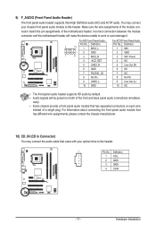
...5 Line Out (R) 6 GND 6 NC 7 FAUDIO_JD 7 NC 8 No Pin 8 No Pin 9 LINE2_L 9 Line Out (L) 10 GND 10 NC • The front panel audio header supports HD audio by default. • Audio signals will make the device unable to work or even damage it. ously. • Some chassis provide a front panel... your chassis front panel audio module to the header. 1 Pin No. 9) F_AUDIO (Front Panel Audio Header) The front panel audio header supports Intel High Definition audio (HD) and AC'97 audio. Make sure the wire assignments of the module connector match the pin assignments of the...
...5 Line Out (R) 6 GND 6 NC 7 FAUDIO_JD 7 NC 8 No Pin 8 No Pin 9 LINE2_L 9 Line Out (L) 10 GND 10 NC • The front panel audio header supports HD audio by default. • Audio signals will make the device unable to work or even damage it. ously. • Some chassis provide a front panel... your chassis front panel audio module to the header. 1 Pin No. 9) F_AUDIO (Front Panel Audio Header) The front panel audio header supports Intel High Definition audio (HD) and AC'97 audio. Make sure the wire assignments of the module connector match the pin assignments of the...

Manual
Page 18
... optional S/PDIF in /out. For purchasing the optional USB bracket, please contact the local dealer. Pin No. 11) SPDIF_IO (S/PDIF In/Out Header) This header supports digital S/PDIF in and out cable, please contact the local dealer. 1 2 5 6 Pin No. 1 2 3 4 5 6 Definition Power No Pin SPDIF SPDIFI GND GND 12) F_USB1/F_USB2 (USB... bracket, be sure to turn off your computer and unplug the power cord from the power outlet to prevent damage to an audio device that supports digital audio out and an audio system that supports digital audio in. Hardware Installation - 18 -
... optional S/PDIF in /out. For purchasing the optional USB bracket, please contact the local dealer. Pin No. 11) SPDIF_IO (S/PDIF In/Out Header) This header supports digital S/PDIF in and out cable, please contact the local dealer. 1 2 5 6 Pin No. 1 2 3 4 5 6 Definition Power No Pin SPDIF SPDIFI GND GND 12) F_USB1/F_USB2 (USB... bracket, be sure to turn off your computer and unplug the power cord from the power outlet to prevent damage to an audio device that supports digital audio out and an audio system that supports digital audio in. Hardware Installation - 18 -
Manual
Page 22
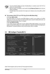
...: Value F10: Save F6: Fail-Safe Defaults ESC: Exit F1: General Help F7: Optimized Defaults (Note) This item appears only if you install a CPU that supports this chapter are for reference only and may differ by BIOS version. The Functions of reconfiguring the BIOS settings. BIOS Setup - 22 - • If...
...: Value F10: Save F6: Fail-Safe Defaults ESC: Exit F1: General Help F7: Optimized Defaults (Note) This item appears only if you install a CPU that supports this chapter are for reference only and may differ by BIOS version. The Functions of reconfiguring the BIOS settings. BIOS Setup - 22 - • If...

Manual
Page 23
... reboot, or clear the CMOS values to reset the board to default values. (Default: Disabled) (Note) This item appears only if you install a CPU that supports this occurs, clear the CMOS values and reset the board to default values.) Robust Graphics Booster Robust Graphics Booster (R.G.B.) helps to enhance the performance of...
... reboot, or clear the CMOS values to reset the board to default values. (Default: Disabled) (Note) This item appears only if you install a CPU that supports this occurs, clear the CMOS values and reset the board to default values.) Robust Graphics Booster Robust Graphics Booster (R.G.B.) helps to enhance the performance of...
Manual
Page 24
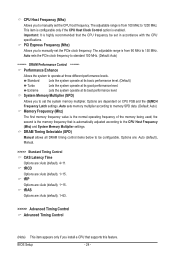
... be set the CPU host frequency. Auto sets memory multiplier according to manually set the PCIe clock frequency. the second is the memory frequency that supports this feature. tRAS Options are: Auto (default), 1~63. >>>>> Advanced Timing Control Advanced Timing Control (Note) This item appears only if you to memory SPD data...
... be set the CPU host frequency. Auto sets memory multiplier according to manually set the PCIe clock frequency. the second is the memory frequency that supports this feature. tRAS Options are: Auto (default), 1~63. >>>>> Advanced Timing Control Advanced Timing Control (Note) This item appears only if you to memory SPD data...
Manual
Page 28
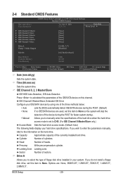
... 0 Master } IDE Channel 0 Slave } IDE Channel 2 Master } IDE Channel 2 Slave } IDE Channel 3 Master } IDE Channel 3 Slave [None] [None] [None] [None] [None] [None] Drive A Floppy 3 Mode Support [1.44M, 3.5"] [Disabled] Halt On [All, But Keyboard] Base Memory Extended Memory Total Memory 640K 2012M 2014M Move Enter: Select F5: Previous Values +/-/PU/PD: Value...
... 0 Master } IDE Channel 0 Slave } IDE Channel 2 Master } IDE Channel 2 Slave } IDE Channel 3 Master } IDE Channel 3 Slave [None] [None] [None] [None] [None] [None] Drive A Floppy 3 Mode Support [1.44M, 3.5"] [Disabled] Halt On [All, But Keyboard] Base Memory Extended Memory Total Memory 640K 2012M 2014M Move Enter: Select F5: Previous Values +/-/PU/PD: Value...
Manual
Page 29
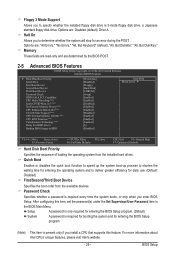
...For more information about Intel CPUs' unique features, please visit Intel's website. - 29 - Halt On Allows you install a CPU that supports this item, set the password(s) under the Set Supervisor/User Password item in the BIOS Main Menu. Options are determined by the BIOS POST... Third Boot Device Password Check HDD S.M.A.R.T. to 3 (Note) No-Execute Memory Protect (Note) CPU Enhanced Halt (C1E) (Note) C2/C2E State Support (Note) CPU Thermal Monitor 2(TM2) (Note) CPU EIST Function (Note) Virtualization Technology (Note) Delay For HDD (Secs) Backup BIOS Image to...
...For more information about Intel CPUs' unique features, please visit Intel's website. - 29 - Halt On Allows you install a CPU that supports this item, set the password(s) under the Set Supervisor/User Password item in the BIOS Main Menu. Options are determined by the BIOS POST... Third Boot Device Password Check HDD S.M.A.R.T. to 3 (Note) No-Execute Memory Protect (Note) CPU Enhanced Halt (C1E) (Note) C2/C2E State Support (Note) CPU Thermal Monitor 2(TM2) (Note) CPU EIST Function (Note) Virtualization Technology (Note) Delay For HDD (Secs) Backup BIOS Image to...
Manual
Page 30
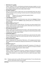
...system halt state. Virtualization enhanced by Intel Virtualization Technology will be reduced during system halt state to Enabled for operating systems that support multi-processor mode. With virtualization, one CPU core. This feature only works for legacy operating system such as multiple virtual ...CPU enter C2/C2E mode in independent partitions. Enabled Enables all CPU cores and multi-threading function when using an Intel CPU that supports this item to descrease power consumption. (Default: Disabled) CPU Thermal Monitor 2 (TM2) (Note) Enables or disables Intel CPU Thermal...
...system halt state. Virtualization enhanced by Intel Virtualization Technology will be reduced during system halt state to Enabled for operating systems that support multi-processor mode. With virtualization, one CPU core. This feature only works for legacy operating system such as multiple virtual ...CPU enter C2/C2E mode in independent partitions. Enabled Enables all CPU cores and multi-threading function when using an Intel CPU that supports this item to descrease power consumption. (Default: Disabled) CPU Thermal Monitor 2 (TM2) (Note) Enables or disables Intel CPU Thermal...
Manual
Page 31
... onboard graphics, whether or not a PCI Express card is not seen by the operating system and not available to any user application. PAVP mode can support increased content protection and robustness requirements for the encryption of compressed video. (Default) Paranoid PAVP Reserves 96 MB of the monitor display from 0 to 15...
... onboard graphics, whether or not a PCI Express card is not seen by the operating system and not available to any user application. PAVP mode can support increased content protection and robustness requirements for the encryption of compressed video. (Default) Paranoid PAVP Reserves 96 MB of the monitor display from 0 to 15...
Manual
Page 32
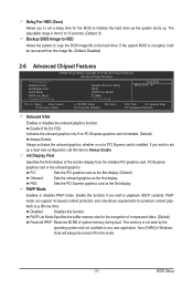
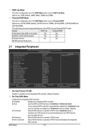
The table below shows the supported features of 4 ATA devices to operate in SATA mode. Enhanced Sets all SATA devices to operate in PATA mode and disables the integrated IDE ... } SMART LAN Onboard LAN Boot ROM Onboard Serial Port 1 Onboard Serial Port 2 Onboard Parallel Port Parallel Port Mode USB 1.0 Controller USB 2.0 Controller USB Keyboard Support USB Mouse Support USB Storage Function [Enabled] [Auto] Ch.0 Master/Slave Ch.2 Master/Slave Ch.3 Master/Slave [Auto] [Enabled] [Disabled] [Press Enter] [Disabled] [3F8/IRQ4] [2F8...
The table below shows the supported features of 4 ATA devices to operate in SATA mode. Enhanced Sets all SATA devices to operate in PATA mode and disables the integrated IDE ... } SMART LAN Onboard LAN Boot ROM Onboard Serial Port 1 Onboard Serial Port 2 Onboard Parallel Port Parallel Port Mode USB 1.0 Controller USB 2.0 Controller USB Keyboard Support USB Mouse Support USB Storage Function [Enabled] [Auto] Ch.0 Master/Slave Ch.2 Master/Slave Ch.3 Master/Slave [Auto] [Enabled] [Disabled] [Press Enter] [Disabled] [3F8/IRQ4] [2F8...
Manual
Page 34
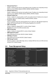
...USB 1.0 controller. (Default: Enabled) Disabled will turn off all of Month) Alarm Everyday x Time (hh:mm:ss) Alarm 0 : 0 : 0 HPET Support (Note) [Enabled] HPET Mode (Note) [32-bit mode] Power On By Mouse [Disabled] Power On By Keyboard [Disabled] x KB Power ON Password ...Enter AC Back Function [Soft-Off] ErP Support [Disabled] Move Enter: Select F5: Previous Values +/-/PU/PD: Value F10: Save F6: Fail-Safe Defaults ESC: Exit F1: General Help...
...USB 1.0 controller. (Default: Enabled) Disabled will turn off all of Month) Alarm Everyday x Time (hh:mm:ss) Alarm 0 : 0 : 0 HPET Support (Note) [Enabled] HPET Mode (Note) [32-bit mode] Power On By Mouse [Disabled] Power On By Keyboard [Disabled] x KB Power ON Password ...Enter AC Back Function [Soft-Off] ErP Support [Disabled] Move Enter: Select F5: Previous Values +/-/PU/PD: Value F10: Save F6: Fail-Safe Defaults ESC: Exit F1: General Help...
Manual
Page 35
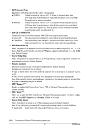
...bit mode) Power On By Mouse Allows the system to be effective. In S3 sleep state, the system appears to be awakened from a modem that supports wake-up function. (Default: Enabled) Resume by a PS/2 mouse wake-up signal from a PCI or PCIe device. Instant-Off Press the power... button and then the system will enter suspend mode. HPET Support (Note) Enables or disables High Precision Event Timer (HPET) for Windows 7/Vista operating system. (Default: Enabled) HPET Mode (Note) Allows you need ...
...bit mode) Power On By Mouse Allows the system to be effective. In S3 sleep state, the system appears to be awakened from a modem that supports wake-up function. (Default: Enabled) Resume by a PS/2 mouse wake-up signal from a PCI or PCIe device. Instant-Off Press the power... button and then the system will enter suspend mode. HPET Support (Note) Enables or disables High Precision Event Timer (HPET) for Windows 7/Vista operating system. (Default: Enabled) HPET Mode (Note) Allows you need ...

