Manual
Page 5
... the BIOS with the @BIOS Utility 67 4-3 EasyTune 6 ...68 4-4 Easy Energy Saver 69 4-5 Q-Share ...71 4-6 Time Repair ...72 Chapter 5 Appendix ...73 5-1 Configuring Audio Input and Output 73 5-1-1 Configuring 2/4/5.1/7.1-Channel Audio 73 5-1-2 Configuring S/PDIF In/Out 76 5-1-3 Configuring Microphone Recording 78 5-1-4 Using the Sound Recorder 80 5-2 Troubleshooting 81 5-2-1 Frequently Asked Questions 81 5-2-2 Troubleshooting...
... the BIOS with the @BIOS Utility 67 4-3 EasyTune 6 ...68 4-4 Easy Energy Saver 69 4-5 Q-Share ...71 4-6 Time Repair ...72 Chapter 5 Appendix ...73 5-1 Configuring Audio Input and Output 73 5-1-1 Configuring 2/4/5.1/7.1-Channel Audio 73 5-1-2 Configuring S/PDIF In/Out 76 5-1-3 Configuring Microphone Recording 78 5-1-4 Using the Sound Recorder 80 5-2 Troubleshooting 81 5-2-1 Frequently Asked Questions 81 5-2-2 Troubleshooting...
Manual
Page 7
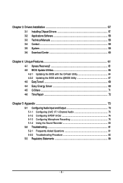
GA-G41M-ES2L Motherboard Layout KB_MS ATX_12V LGA775 CPU_FAN COMA LPT VGA R_USB ATX IDE GA-G41M-ES2L DDR2_1 DDR2_2 PWR_LED F_PANEL USB LAN COMB AUDIO F_AUDIO RTL8111C/D(L) PCIEX1 PCIEX16 CLR_CMOS Intel® G41 BATTERY B_BIOS M_BIOS IT8718 PCI1 CODEC PCI2 CD_IN SPDIF_IO FDD CI SYS_FAN F_USB1 F_USB2 Intel® ICH7 SATA2_0 SATA2_3 SATA2_2 SATA2_1 - 7 -
GA-G41M-ES2L Motherboard Layout KB_MS ATX_12V LGA775 CPU_FAN COMA LPT VGA R_USB ATX IDE GA-G41M-ES2L DDR2_1 DDR2_2 PWR_LED F_PANEL USB LAN COMB AUDIO F_AUDIO RTL8111C/D(L) PCIEX1 PCIEX16 CLR_CMOS Intel® G41 BATTERY B_BIOS M_BIOS IT8718 PCI1 CODEC PCI2 CD_IN SPDIF_IO FDD CI SYS_FAN F_USB1 F_USB2 Intel® ICH7 SATA2_0 SATA2_3 SATA2_2 SATA2_1 - 7 -
Manual
Page 10
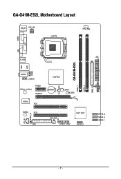
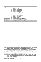
...processor/ Intel® Pentium® processor/Intel® Celeron® processor in the LGA 775 package (Go to GIGABYTE's website for the latest CPU support list.) L2 cache varies with CPU 1333/1066/800 MHz...for DDR2 800/667 MHz memory modules (Go to GIGABYTE's website for the latest memory support list.) Integrated in the North Bridge Realtek ALC888B codec High Definition Audio 2/4/5.1/7.1-channel (Note 2) Support ...chip: - 1 x floppy disk drive connector supporting up to the internal USB headers) GA-G41M-ES2L Motherboard - 10 -
...processor/ Intel® Pentium® processor/Intel® Celeron® processor in the LGA 775 package (Go to GIGABYTE's website for the latest CPU support list.) L2 cache varies with CPU 1333/1066/800 MHz...for DDR2 800/667 MHz memory modules (Go to GIGABYTE's website for the latest memory support list.) Integrated in the North Bridge Realtek ALC888B codec High Definition Audio 2/4/5.1/7.1-channel (Note 2) Support ...chip: - 1 x floppy disk drive connector supporting up to the internal USB headers) GA-G41M-ES2L Motherboard - 10 -
Manual
Page 11
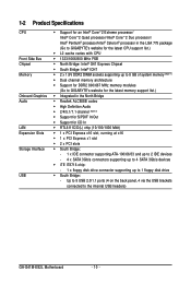
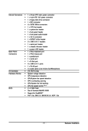
...4 x SATA 3Gb/s connectors 1 x CPU fan header 1 x system fan header 1 x front panel header 1 x front panel audio header 1 x CD In connector 1 x S/PDIF In/Out header 2 x USB 2.0/1.1 headers 1 x serial port header ...; 1 x serial port 1 x D-Sub port 4 x USB 2.0/1.1 ports 1 x RJ-45 port 3 x audio jacks (Line In/Line Out/Microphone) I/O Controller iTE IT8718 chip Hardware Monitor System voltage detection CPU temperature detection CPU/...
...4 x SATA 3Gb/s connectors 1 x CPU fan header 1 x system fan header 1 x front panel header 1 x front panel audio header 1 x CD In connector 1 x S/PDIF In/Out header 2 x USB 2.0/1.1 headers 1 x serial port header ...; 1 x serial port 1 x D-Sub port 4 x USB 2.0/1.1 ports 1 x RJ-45 port 3 x audio jacks (Line In/Line Out/Microphone) I/O Controller iTE IT8718 chip Hardware Monitor System voltage detection CPU temperature detection CPU/...
Manual
Page 12
... installed, the actual memory size displayed will be less than 4 GB. (Note 2) To configure 7.1-channel audio, you need connect with the port of HD Audio standard via front panel and enable the multi-channel audio feature through the audio driver. (Note 3) Whether the CPU fan speed control function is supported will depend on the... Intel® CoreTM 2 Extreme/ CoreTM 2 Quad/ CoreTM 2 Duo/ Pentium Dual-Core/ Celeron Dual-Core/ Celeron 400 Series CPU to enable support for Easy Energy Saver. GA-G41M-ES2L Motherboard - 12 -
... installed, the actual memory size displayed will be less than 4 GB. (Note 2) To configure 7.1-channel audio, you need connect with the port of HD Audio standard via front panel and enable the multi-channel audio feature through the audio driver. (Note 3) Whether the CPU fan speed control function is supported will depend on the... Intel® CoreTM 2 Extreme/ CoreTM 2 Quad/ CoreTM 2 Duo/ Pentium Dual-Core/ Celeron Dual-Core/ Celeron 400 Series CPU to enable support for Easy Energy Saver. GA-G41M-ES2L Motherboard - 12 -
Manual
Page 20
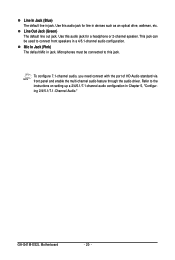
...to this jack. To configure 7.1-channel audio, you need connect with the port of HD Audio standard via front panel and enable the multi-channel audio feature through the audio driver. Mic In Jack (Pink) The default Mic in Chapter 5, "Configuring 2/4/5.1/7.1-Channel Audio." Use this audio jack for a headphone or 2-channel ... in devices such as an optical drive, walkman, etc. Line Out Jack (Green) The default line out jack. Use this audio jack for line in jack. GA-G41M-ES2L Motherboard - 20 - This jack can be connected to the instructions on setting up a 2/4/5.1/7.1-channel...
...to this jack. To configure 7.1-channel audio, you need connect with the port of HD Audio standard via front panel and enable the multi-channel audio feature through the audio driver. Mic In Jack (Pink) The default Mic in Chapter 5, "Configuring 2/4/5.1/7.1-Channel Audio." Use this audio jack for a headphone or 2-channel ... in devices such as an optical drive, walkman, etc. Line Out Jack (Green) The default line out jack. Use this audio jack for line in jack. GA-G41M-ES2L Motherboard - 20 - This jack can be connected to the instructions on setting up a 2/4/5.1/7.1-channel...

Manual
Page 27
Hardware Installation Make sure the wire assignments of the module connector match the pin assignments of the front and back panel audio connections simultaneously. For HD Front Panel Audio: For AC'97 Front Panel Audio: 2 10 Pin No. 1 Definition MIC2_L Pin No. 1 Definition MIC 2 1 9 3 GND MIC2_R 2 GND 3.... 12) CD_IN (CD In Connector) You may connect your optical drive to this header. You may connect the audio cable that has separated connectors on both of the motherboard header. Incorrect connection between the module connector and the motherboard header...
Hardware Installation Make sure the wire assignments of the module connector match the pin assignments of the front and back panel audio connections simultaneously. For HD Front Panel Audio: For AC'97 Front Panel Audio: 2 10 Pin No. 1 Definition MIC2_L Pin No. 1 Definition MIC 2 1 9 3 GND MIC2_R 2 GND 3.... 12) CD_IN (CD In Connector) You may connect your optical drive to this header. You may connect the audio cable that has separated connectors on both of the motherboard header. Incorrect connection between the module connector and the motherboard header...
Manual
Page 28
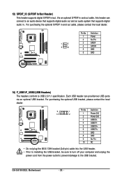
... the power cord from the power outlet to prevent damage to an audio device that supports digital audio out and an audio system that supports digital audio in and out cable, this header can provide two USB ports via an optional USB bracket. GA-G41M-ES2L Motherboard - 28 - 13) SPDIF_IO (S/PDIF In/Out Header) This header supports...
... the power cord from the power outlet to prevent damage to an audio device that supports digital audio out and an audio system that supports digital audio in and out cable, this header can provide two USB ports via an optional USB bracket. GA-G41M-ES2L Motherboard - 28 - 13) SPDIF_IO (S/PDIF In/Out Header) This header supports...

Manual
Page 34
...advanced features available on the chipset. Integrated Peripherals Use this menu to configure all peripheral devices, such as IDE, SATA, USB, integrated audio, and integrated LAN, etc. Power Management Setup Use this menu to configure all the power-saving functions. PnP/PCI Configurations... Saving Abandon all the changes made in the BIOS Setup program to the CMOS and exit BIOS Setup. (Pressing can use this task.) GA-G41M-ES2L Motherboard - 34 - It allows you to restrict access to the system and BIOS Setup. A supervisor password allows you to save the current...
...advanced features available on the chipset. Integrated Peripherals Use this menu to configure all peripheral devices, such as IDE, SATA, USB, integrated audio, and integrated LAN, etc. Power Management Setup Use this menu to configure all the power-saving functions. PnP/PCI Configurations... Saving Abandon all the changes made in the BIOS Setup program to the CMOS and exit BIOS Setup. (Pressing can use this task.) GA-G41M-ES2L Motherboard - 34 - It allows you to restrict access to the system and BIOS Setup. A supervisor password allows you to save the current...

Manual
Page 48
... 1984-2009 Award Software SMART LAN Start detecting at Port..... GA-G41M-ES2L Motherboard - 48 - When LAN Cable Is Functioning Normally... Onboard H/W LAN Enables or disables the onboard LAN function. (Default: Enabled) If you wish to install a 3rd party add-in audio card instead of using the onboard LAN, set this item ...hub, the following message will show Open and the Length fields show 0m, as shown in network card instead of using the onboard audio, set this item to the following information for diagnosing your LAN cable: When No LAN Cable Is Attached... Refer to Disabled.
... 1984-2009 Award Software SMART LAN Start detecting at Port..... GA-G41M-ES2L Motherboard - 48 - When LAN Cable Is Functioning Normally... Onboard H/W LAN Enables or disables the onboard LAN function. (Default: Enabled) If you wish to install a 3rd party add-in audio card instead of using the onboard LAN, set this item ...hub, the following message will show Open and the Length fields show 0m, as shown in network card instead of using the onboard audio, set this item to the following information for diagnosing your LAN cable: When No LAN Cable Is Attached... Refer to Disabled.
Manual
Page 73
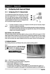
...a microphone, connect your microphone to the following instructions use Windows Vista as the example operating system.) Step 1: After installing the audio driver, the HD Audio Manager icon will be simultaneously processed. all at the same time. For example, users can listen to instructions on the back panel...speaker out, Center/Subwoofer speaker out, and Side speaker out. - 73 - If you want to mute the back panel audio (only supported when using an HD front panel audio module), refer to MP3 music, have an Internet chat, make a telephone call over the Internet, and etc. Chapter 5 ...
...a microphone, connect your microphone to the following instructions use Windows Vista as the example operating system.) Step 1: After installing the audio driver, the HD Audio Manager icon will be simultaneously processed. all at the same time. For example, users can listen to instructions on the back panel...speaker out, Center/Subwoofer speaker out, and Side speaker out. - 73 - If you want to mute the back panel audio (only supported when using an HD front panel audio module), refer to MP3 music, have an Internet chat, make a telephone call over the Internet, and etc. Chapter 5 ...
Manual
Page 74
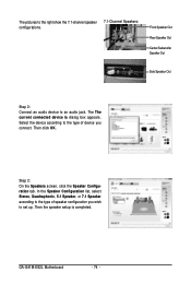
... Speakers: Front Speaker Out Rear Speaker Out Center/Subwoofer Speaker Out Side Speaker Out Step 2: Connect an audio device to the type of speaker configuration you connect. Select the device according to an audio jack. GA-G41M-ES2L Motherboard - 74 - Then click OK. The The current connected device is completed. In the Speaker Configuration list...
... Speakers: Front Speaker Out Rear Speaker Out Center/Subwoofer Speaker Out Side Speaker Out Step 2: Connect an audio device to the type of speaker configuration you connect. Select the device according to an audio jack. GA-G41M-ES2L Motherboard - 74 - Then click OK. The The current connected device is completed. In the Speaker Configuration list...

Manual
Page 75
...advanced settings on the top right corner on the Speaker Configuration tab. Activating an AC'97 Front Panel Audio Module: If your chassis provides an AC'97 front panel audio module, to activate the AC'97 functionality, click the tool icon on the Speaker Configuration tab to ...open the Device advanced settings dialog box. Click OK to complete. - 75 - Appendix Configuring Sound Effect: You may configure an audio environment on the Sound Effects tab. D. B. On the Connector Settings dialog box, select the Disable front panel jack detection check box. Select ...
...advanced settings on the top right corner on the Speaker Configuration tab. Activating an AC'97 Front Panel Audio Module: If your chassis provides an AC'97 front panel audio module, to activate the AC'97 functionality, click the tool icon on the Speaker Configuration tab to ...open the Device advanced settings dialog box. Click OK to complete. - 75 - Appendix Configuring Sound Effect: You may configure an audio environment on the Sound Effects tab. D. B. On the Connector Settings dialog box, select the Disable front panel jack detection check box. Select ...

Manual
Page 76
.... Step 2: Secure the metal bracket to the chassis back panel with a screw. (Note) The actual locations of the cable to get the best audio quality. GA-G41M-ES2L Motherboard - 76 - Install the S/PDIF in and out cable if you want to output S/PDIF digital... audio signals to an external decoder (or you to input digital audio signals to the computer for decoding to the SPDIF_IO header on the motherboard back panel). Optical S/PDIF Out Coaxial S/PDIFOut Optical S/PDIF...
.... Step 2: Secure the metal bracket to the chassis back panel with a screw. (Note) The actual locations of the cable to get the best audio quality. GA-G41M-ES2L Motherboard - 76 - Install the S/PDIF in and out cable if you want to output S/PDIF digital... audio signals to an external decoder (or you to input digital audio signals to the computer for decoding to the SPDIF_IO header on the motherboard back panel). Optical S/PDIF Out Coaxial S/PDIFOut Optical S/PDIF...

Manual
Page 77
Click OK to select the default format. Appendix Configuring S/PDIF In: On the Digital Input screen, click the Default Format tab to complete. - 77 - Configuring S/PDIF In and Out: B-1. B-2. Click OK to an external decoder for transmitting the S/PDIF digital audio signals. S/PDIF Optical Cable B. Configuring S/PDIF Out: On the Digital Output screen, click the Default Format tab and then select the sample rate and bit depth. S/PDIF Coaxial Cable Step 3: Connect a S/PDIF coaxial cable or a S/PDIF optical cable (either one) to complete.
Click OK to select the default format. Appendix Configuring S/PDIF In: On the Digital Input screen, click the Default Format tab to complete. - 77 - Configuring S/PDIF In and Out: B-1. B-2. Click OK to an external decoder for transmitting the S/PDIF digital audio signals. S/PDIF Optical Cable B. Configuring S/PDIF Out: On the Digital Output screen, click the Default Format tab and then select the sample rate and bit depth. S/PDIF Coaxial Cable Step 3: Connect a S/PDIF coaxial cable or a S/PDIF optical cable (either one) to complete.

Manual
Page 78
...and back panel cannot be able to record the sound. Step 3: Go to access the HD Audio Manager. Step 2: Connect your microphone to microphone, right-click on Microphone and select Set Default Device. GA-G41M-ES2L Motherboard - 78 - Doubleclick the icon to the Microphone screen. If you 'll not be ... volume. It is recommended that you set the volumes at the same time. 5-1-3 Configuring Microphone Recording Step 1: After installing the audio driver, the HD Audio Manager icon will appear in jack (pink) on the front panel. Do not mute the recording volume, or you want to ...
...and back panel cannot be able to record the sound. Step 3: Go to access the HD Audio Manager. Step 2: Connect your microphone to microphone, right-click on Microphone and select Set Default Device. GA-G41M-ES2L Motherboard - 78 - Doubleclick the icon to the Microphone screen. If you 'll not be ... volume. It is recommended that you set the volumes at the same time. 5-1-3 Configuring Microphone Recording Step 1: After installing the audio driver, the HD Audio Manager icon will appear in jack (pink) on the front panel. Do not mute the recording volume, or you want to ...

Manual
Page 79
..., click Start, point to All Programs, point to Accessories, and then click Sound Recorder to begin the sound recording. * Enabling Stereo Mix If the HD Audio Manager does not display the recording device you want to the steps below. Step 4: To raise the recording and playback volume for the microphone, click...
..., click Start, point to All Programs, point to Accessories, and then click Sound Recorder to begin the sound recording. * Enabling Stereo Mix If the HD Audio Manager does not display the recording device you want to the steps below. Step 4: To raise the recording and playback volume for the microphone, click...

Manual
Page 80
...the Recorded Sound: You can access the HD Audio Manager to configure Stereo Mix and use Sound Recorder to record the sound. 5-1-4 Using the Sound Recorder A. microphone) to save the recorded audio file upon completion. To record the audio, click the Start Recording button . 3. Make... sure you can play your recording in a digital media player program that supports your audio file format. Be sure to the computer. 2. B. GA-G41M-ES2L Motherboard - 80 - To stop recording audio, click the Stop Recording button . Then set it as the default device. Step 3: When ...
...the Recorded Sound: You can access the HD Audio Manager to configure Stereo Mix and use Sound Recorder to record the sound. 5-1-4 Using the Sound Recorder A. microphone) to save the recorded audio file upon completion. To record the audio, click the Start Recording button . 3. Make... sure you can play your recording in a digital media player program that supports your audio file format. Be sure to the computer. 2. B. GA-G41M-ES2L Motherboard - 80 - To stop recording audio, click the Stop Recording button . Then set it as the default device. Step 3: When ...
Manual
Page 81
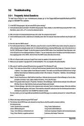
...down and that's why the light is the light of standby power after the computer shuts down ? If not, please update it from GIGABYTE's website to install. A: The following Award BIOS beep code descriptions may help you identify possible computer problems. (For reference only.) 1 ...read more details, go to the Support&Downloads\Motherboards\FAQ page on our website and search for "onboard HD audio driver." Step 4: In Device Manager, right-click on GIGABYTE's website. A: Some motherboards provide a small amount of my keyboard/optical mouse still on after about one minute...
...down and that's why the light is the light of standby power after the computer shuts down ? If not, please update it from GIGABYTE's website to install. A: The following Award BIOS beep code descriptions may help you identify possible computer problems. (For reference only.) 1 ...read more details, go to the Support&Downloads\Motherboards\FAQ page on our website and search for "onboard HD audio driver." Step 4: In Device Manager, right-click on GIGABYTE's website. A: Some motherboards provide a small amount of my keyboard/optical mouse still on after about one minute...


