Manual
Page 1
GA-G41M-ES2L LGA775 socket motherboard for Intel® CoreTM processor family/ Intel® Pentium® processor family/Intel® Celeron® processor family User's Manual Rev. 1101 12ME-G41MES2L-1101R
GA-G41M-ES2L LGA775 socket motherboard for Intel® CoreTM processor family/ Intel® Pentium® processor family/Intel® Celeron® processor family User's Manual Rev. 1101 12ME-G41MES2L-1101R

Manual
Page 2
Motherboard GA-G41M-ES2L Mar. 27, 2009 Motherboard GA-G41M-ES2L Mar. 27, 2009
Motherboard GA-G41M-ES2L Mar. 27, 2009 Motherboard GA-G41M-ES2L Mar. 27, 2009
Manual
Page 3
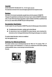
...copyright laws and is 1.0. All rights reserved. Changes to use GIGABYTE's unique features, read or download the information on/from the Support\Motherboard\Technology Guide page on your motherboard revision before updating motherboard BIOS, drivers, or when looking for technical information. Disclaimer Information ...in this : "REV: X.X." Example: For product-related information, check on our website at: http://www.gigabyte.com.tw Identifying Your Motherboard Revision The revision number on our website. Documentation Classifications In order to assist in the use of documentations: &#...
...copyright laws and is 1.0. All rights reserved. Changes to use GIGABYTE's unique features, read or download the information on/from the Support\Motherboard\Technology Guide page on your motherboard revision before updating motherboard BIOS, drivers, or when looking for technical information. Disclaimer Information ...in this : "REV: X.X." Example: For product-related information, check on our website at: http://www.gigabyte.com.tw Identifying Your Motherboard Revision The revision number on our website. Documentation Classifications In order to assist in the use of documentations: &#...
Manual
Page 4
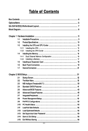
Table of Contents Box Contents ...6 OptionalItems...6 GA-G41M-ES2L Motherboard Layout 7 Block Diagram...8 Chapter 1 Hardware Installation 9 1-1 Installation Precautions 9 1-2 Product Specifications 10 1-3 Installing the CPU and CPU Cooler 13 1-3-1 Installing the CPU 13 1-3-2 Installing the CPU ...
Table of Contents Box Contents ...6 OptionalItems...6 GA-G41M-ES2L Motherboard Layout 7 Block Diagram...8 Chapter 1 Hardware Installation 9 1-1 Installation Precautions 9 1-2 Product Specifications 10 1-3 Installing the CPU and CPU Cooler 13 1-3-1 Installing the CPU 13 1-3-2 Installing the CPU ...

Manual
Page 6
The box contents are for reference only. Optional Items 2-port USB 2.0 bracket (Part No. 12CR1-1UB030-5*R) 2-port SATA power cable (Part No. 12CF1-2SERPW-0*R) S/PDIF in and out cable (Part No. 12CR1-1SPINO-1*R) COM port cable (Part No. 12CF1-1CM001-3*R) - 6 - Box Contents GA-G41M-ES2L motherboard Motherboard driver disk User's Manual One IDE cable Two SATA 3Gb/s cables I/O Shield • The box contents above are subject to change without notice. • The motherboard image is for reference only and the actual items shall depend on the product package you obtain.
The box contents are for reference only. Optional Items 2-port USB 2.0 bracket (Part No. 12CR1-1UB030-5*R) 2-port SATA power cable (Part No. 12CF1-2SERPW-0*R) S/PDIF in and out cable (Part No. 12CR1-1SPINO-1*R) COM port cable (Part No. 12CF1-1CM001-3*R) - 6 - Box Contents GA-G41M-ES2L motherboard Motherboard driver disk User's Manual One IDE cable Two SATA 3Gb/s cables I/O Shield • The box contents above are subject to change without notice. • The motherboard image is for reference only and the actual items shall depend on the product package you obtain.
Manual
Page 7
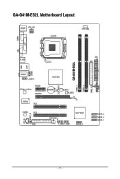
GA-G41M-ES2L Motherboard Layout KB_MS ATX_12V LGA775 CPU_FAN COMA LPT VGA R_USB ATX IDE GA-G41M-ES2L DDR2_1 DDR2_2 PWR_LED F_PANEL USB LAN COMB AUDIO F_AUDIO RTL8111C/D(L) PCIEX1 PCIEX16 CLR_CMOS Intel® G41 BATTERY B_BIOS M_BIOS IT8718 PCI1 CODEC PCI2 CD_IN SPDIF_IO FDD CI SYS_FAN F_USB1 F_USB2 Intel® ICH7 SATA2_0 SATA2_3 SATA2_2 SATA2_1 - 7 -
GA-G41M-ES2L Motherboard Layout KB_MS ATX_12V LGA775 CPU_FAN COMA LPT VGA R_USB ATX IDE GA-G41M-ES2L DDR2_1 DDR2_2 PWR_LED F_PANEL USB LAN COMB AUDIO F_AUDIO RTL8111C/D(L) PCIEX1 PCIEX16 CLR_CMOS Intel® G41 BATTERY B_BIOS M_BIOS IT8718 PCI1 CODEC PCI2 CD_IN SPDIF_IO FDD CI SYS_FAN F_USB1 F_USB2 Intel® ICH7 SATA2_0 SATA2_3 SATA2_2 SATA2_1 - 7 -
Manual
Page 9
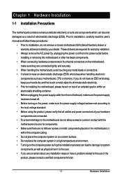
...manual and follow these procedures: • Prior to wear an electrostatic discharge (ESD) wrist strap when handling electronic components such as a motherboard, CPU or memory. Hardware Installation These stickers are required for warranty validation. • Always remove the AC power by your dealer.... Chapter 1 Hardware Installation 1-1 Installation Precautions The motherboard contains numerous delicate electronic circuits and components which can become damaged as physical harm to the user. • If you do...
...manual and follow these procedures: • Prior to wear an electrostatic discharge (ESD) wrist strap when handling electronic components such as a motherboard, CPU or memory. Hardware Installation These stickers are required for warranty validation. • Always remove the AC power by your dealer.... Chapter 1 Hardware Installation 1-1 Installation Precautions The motherboard contains numerous delicate electronic circuits and components which can become damaged as physical harm to the user. • If you do...
Manual
Page 10
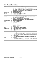
...to 8 GB of system memory (Note 1) Dual channel memory architecture Support for DDR2 800/667 MHz memory modules (Go to GIGABYTE's website for the latest memory support list.) Integrated in the North Bridge Realtek ALC888B codec High Definition Audio ... up to 4 SATA 3Gb/s devices iTE IT8718 chip: - 1 x floppy disk drive connector supporting up to the internal USB headers) GA-G41M-ES2L Motherboard - 10 - Up to 8 USB 2.0/1.1 ports (4 on the back panel, 4 via the USB brackets connected to 1 floppy disk drive South Bridge: -
...to 8 GB of system memory (Note 1) Dual channel memory architecture Support for DDR2 800/667 MHz memory modules (Go to GIGABYTE's website for the latest memory support list.) Integrated in the North Bridge Realtek ALC888B codec High Definition Audio ... up to 4 SATA 3Gb/s devices iTE IT8718 chip: - 1 x floppy disk drive connector supporting up to the internal USB headers) GA-G41M-ES2L Motherboard - 10 - Up to 8 USB 2.0/1.1 ports (4 on the back panel, 4 via the USB brackets connected to 1 floppy disk drive South Bridge: -
Manual
Page 12
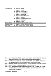
GA-G41M-ES2L Motherboard - 12 - Unique Features Bundled Software Operating System Form Factor Support for @BIOS Support for Q-Flash Support for Virtual DualBIOS Support for .... (Note 3) Whether the CPU fan speed control function is supported will depend on the CPU you install. (Note 4) Available functions in EasyTune may differ by motherboard model. (Note 5) Due to the hardware limitation, you must install the Intel® CoreTM 2 Extreme/ CoreTM 2 Quad/ CoreTM 2 Duo/ Pentium Dual-Core/ Celeron Dual-Core...
GA-G41M-ES2L Motherboard - 12 - Unique Features Bundled Software Operating System Form Factor Support for @BIOS Support for Q-Flash Support for Virtual DualBIOS Support for .... (Note 3) Whether the CPU fan speed control function is supported will depend on the CPU you install. (Note 4) Available functions in EasyTune may differ by motherboard model. (Note 5) Due to the hardware limitation, you must install the Intel® CoreTM 2 Extreme/ CoreTM 2 Quad/ CoreTM 2 Duo/ Pentium Dual-Core/ Celeron Dual-Core...

Manual
Page 13
...may occur. • Set the CPU host frequency in accordance with the CPU specifications. Hardware Installation Locate the alignment keys on the motherboard CPU socket and the notches on the CPU - 13 - LGA775 CPU Socket Alignment Key LGA 775 CPU Alignment Key Pin One Corner... hardware specifications including the CPU, graphics card, memory, hard drive, etc. 1-3-1 Installing the CPU A. mended that the motherboard supports the CPU. (Go to GIGABYTE's website for the peripherals. The CPU cannot be set the frequency beyond hardware specifications since it does not meet the standard...
...may occur. • Set the CPU host frequency in accordance with the CPU specifications. Hardware Installation Locate the alignment keys on the motherboard CPU socket and the notches on the CPU - 13 - LGA775 CPU Socket Alignment Key LGA 775 CPU Alignment Key Pin One Corner... hardware specifications including the CPU, graphics card, memory, hard drive, etc. 1-3-1 Installing the CPU A. mended that the motherboard supports the CPU. (Go to GIGABYTE's website for the peripherals. The CPU cannot be set the frequency beyond hardware specifications since it does not meet the standard...
Manual
Page 14
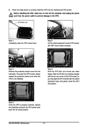
... touch socket contacts.) Step 3: Remove the protective socket cover from the power outlet to prevent damage to correctly install the CPU into its locked position. GA-G41M-ES2L Motherboard - 14 - B. Follow the steps below to the CPU. Before installing the CPU, make sure to turn off the computer and unplug the power cord from..., always replace the protective socket cover when the CPU is properly inserted, replace the load plate and push the CPU socket lever back into the motherboard CPU socket.
... touch socket contacts.) Step 3: Remove the protective socket cover from the power outlet to prevent damage to correctly install the CPU into its locked position. GA-G41M-ES2L Motherboard - 14 - B. Follow the steps below to the CPU. Before installing the CPU, make sure to turn off the computer and unplug the power cord from..., always replace the protective socket cover when the CPU is properly inserted, replace the load plate and push the CPU socket lever back into the motherboard CPU socket.

Manual
Page 15
... After the installation, check the back of arrow is to remove the cooler, on the contrary, is to the CPU fan header (CPU_FAN) on the motherboard. (The following procedure uses Intel® boxed cooler as the picture above, the installation is inserted as the example cooler.) Step 1: Apply an even and....) Step 3: Place the cooler atop the CPU, aligning the four push pins through the pin holes on the surface of thermal grease on the motherboard. Push down each push pin. Check that the Male and Female push pins are joined closely. (Refer to your CPU cooler installation manual for ...
... After the installation, check the back of arrow is to remove the cooler, on the contrary, is to the CPU fan header (CPU_FAN) on the motherboard. (The following procedure uses Intel® boxed cooler as the picture above, the installation is inserted as the example cooler.) Step 1: Apply an even and....) Step 3: Place the cooler atop the CPU, aligning the four push pins through the pin holes on the surface of thermal grease on the motherboard. Push down each push pin. Check that the Male and Female push pins are joined closely. (Refer to your CPU cooler installation manual for ...

Manual
Page 16
.... • Memory modules have a foolproof design. After the memory is recommended that memory of the memory. GA-G41M-ES2L Motherboard - 16 - Dual Channel mode cannot be used . (Go to GIGABYTE's website for the latest memory support list.) • Always turn off the computer and unplug the power cord... from the power outlet before installing the memory in only one DDR2 memory module is recommended that the motherboard supports the memory. When...
.... • Memory modules have a foolproof design. After the memory is recommended that memory of the memory. GA-G41M-ES2L Motherboard - 16 - Dual Channel mode cannot be used . (Go to GIGABYTE's website for the latest memory support list.) • Always turn off the computer and unplug the power cord... from the power outlet before installing the memory in only one DDR2 memory module is recommended that the motherboard supports the memory. When...

Manual
Page 17
... the left, place your memory modules in one direction. Step 2: The clips at both ends of the memory socket. Place the memory module on this motherboard. Hardware Installation Notch DDR2 DIMM A DDR2 memory module has a notch, so it vertically into place when the memory module is securely inserted. - 17 - Spread the...
... the left, place your memory modules in one direction. Step 2: The clips at both ends of the memory socket. Place the memory module on this motherboard. Hardware Installation Notch DDR2 DIMM A DDR2 memory module has a notch, so it vertically into place when the memory module is securely inserted. - 17 - Spread the...
Manual
Page 18
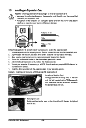
...Locate an expansion slot that came with your operating system. Secure the card's metal bracket to install an expansion card: • Make sure the motherboard supports the expansion card. Make sure the card is fully inserted into the slot. 4. Align the card with the expansion card in the expansion... Removing the Card: Gently push back on the lever on the top edge of the card until it is securely seated in the slot. 3. GA-G41M-ES2L Motherboard - 18 - Turn on the card are completely inserted into the PCI Express x16 slot. If necessary, go to BIOS Setup to correctly install your...
...Locate an expansion slot that came with your operating system. Secure the card's metal bracket to install an expansion card: • Make sure the motherboard supports the expansion card. Make sure the card is fully inserted into the slot. 4. Align the card with the expansion card in the expansion... Removing the Card: Gently push back on the lever on the top edge of the card until it is securely seated in the slot. 3. GA-G41M-ES2L Motherboard - 18 - Turn on the card are completely inserted into the PCI Express x16 slot. If necessary, go to BIOS Setup to correctly install your...
Manual
Page 19
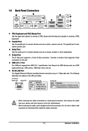
... inside the cable connector. - 19 - USB 2.0/1.1 Port The USB port supports the USB 2.0/1.1 specification. Use this port. Do not rock it straight out from the motherboard. • When removing the cable, pull it side to side to connect devices such as a mouse, modem or other peripherals. The following describes the states...
... inside the cable connector. - 19 - USB 2.0/1.1 Port The USB port supports the USB 2.0/1.1 specification. Use this port. Do not rock it straight out from the motherboard. • When removing the cable, pull it side to side to connect devices such as a mouse, modem or other peripherals. The following describes the states...
Manual
Page 20
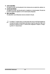
... or 2-channel speaker. Mic In Jack (Pink) The default Mic in jack. Microphones must be used to connect front speakers in Chapter 5, "Configuring 2/4/5.1/7.1-Channel Audio." GA-G41M-ES2L Motherboard - 20 - Line Out Jack (Green) The default line out jack. This jack can be connected to the instructions on setting up a 2/4/5.1/7.1-channel audio configuration in...
... or 2-channel speaker. Mic In Jack (Pink) The default Mic in jack. Microphones must be used to connect front speakers in Chapter 5, "Configuring 2/4/5.1/7.1-Channel Audio." GA-G41M-ES2L Motherboard - 20 - Line Out Jack (Green) The default line out jack. This jack can be connected to the instructions on setting up a 2/4/5.1/7.1-channel audio configuration in...
Manual
Page 21
... devices and your devices are compliant with the connectors you wish to connect. • Before installing the devices, be sure to the connector on the motherboard. - 21 -
... devices and your devices are compliant with the connectors you wish to connect. • Before installing the devices, be sure to the connector on the motherboard. - 21 -

Manual
Page 22
...cable into pins under the protective cover when using a 2x12 power supply, remove the protective cover from the main power connector on the motherboard. Before connecting the power connector, first make sure the power supply is recommended that a power supply that can withstand high power consumption ...-12V GND PS_ON(soft On/Off) GND GND GND -5V +5V +5V +5V (Only for 2x12-pinATX) GND (Only for 2x12-pin ATX) GA-G41M-ES2L Motherboard - 22 - Connect the power supply cable to all devices are properly installed. 1/2) ATX_12V/ATX (2x2 12V Power Connector and 2x12 Main Power Connector) ...
...cable into pins under the protective cover when using a 2x12 power supply, remove the protective cover from the main power connector on the motherboard. Before connecting the power connector, first make sure the power supply is recommended that a power supply that can withstand high power consumption ...-12V GND PS_ON(soft On/Off) GND GND GND -5V +5V +5V +5V (Only for 2x12-pinATX) GND (Only for 2x12-pin ATX) GA-G41M-ES2L Motherboard - 22 - Connect the power supply cable to all devices are properly installed. 1/2) ATX_12V/ATX (2x2 12V Power Connector and 2x12 Main Power Connector) ...

Manual
Page 23
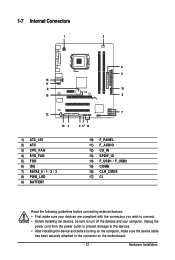
3/4) CPU_FAN/SYS_FAN (Fan Headers) The motherboard has a 4-pin CPU fan header (CPU_FAN) and a 3-pin (SYS_FAN) system fan header. Overheating may result in the correct orientation (the black connector wire is typically ...designated by a stripe of the connector and the floppy disk drive cable. The types of a CPU fan with fan speed control design. The motherboard supports CPU fan speed control, which requires the use of floppy disk drives supported are not configuration jumper blocks. For optimum heat dissipation, it in...
3/4) CPU_FAN/SYS_FAN (Fan Headers) The motherboard has a 4-pin CPU fan header (CPU_FAN) and a 3-pin (SYS_FAN) system fan header. Overheating may result in the correct orientation (the black connector wire is typically ...designated by a stripe of the connector and the floppy disk drive cable. The types of a CPU fan with fan speed control design. The motherboard supports CPU fan speed control, which requires the use of floppy disk drives supported are not configuration jumper blocks. For optimum heat dissipation, it in...


