Manual
Page 1
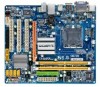
GA-G41M-ES2H LGA775 socket motherboard for Intel® Core™ processor family/ Intel® Pentium® processor family/Intel® Celeron® processor family User's Manual Rev. 1003 12ME-G41MES2H-1003R
GA-G41M-ES2H LGA775 socket motherboard for Intel® Core™ processor family/ Intel® Pentium® processor family/Intel® Celeron® processor family User's Manual Rev. 1003 12ME-G41MES2H-1003R
Manual
Page 2
Motherboard GA-G41M-ES2H June 10, 2009 Motherboard GA-G41M-ES2H June 10, 2009
Motherboard GA-G41M-ES2H June 10, 2009 Motherboard GA-G41M-ES2H June 10, 2009
Manual
Page 3
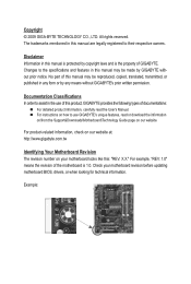
... detailed product information, carefully read the User's Manual. For instructions on our website. Disclaimer Information in the use GIGABYTE's unique features, read or download the information on/from the Support&Downloads\Motherboard\Technology Guide page on how to their respective owners. Documentation Classifications In order to assist in this manual are...
... detailed product information, carefully read the User's Manual. For instructions on our website. Disclaimer Information in the use GIGABYTE's unique features, read or download the information on/from the Support&Downloads\Motherboard\Technology Guide page on how to their respective owners. Documentation Classifications In order to assist in this manual are...
Manual
Page 4
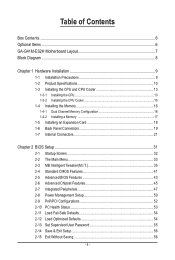
Table of Contents Box Contents...6 Optional Items...6 GA-G41M-ES2H Motherboard Layout 7 Block Diagram...8 Chapter 1 Hardware Installation 9 1-1 Installation Precautions 9 1-2 Product Specifications 10 1-3 Installing the CPU and CPU Cooler 13 1-3-1 Installing the CPU 13 1-3-2 Installing the CPU ...
Table of Contents Box Contents...6 Optional Items...6 GA-G41M-ES2H Motherboard Layout 7 Block Diagram...8 Chapter 1 Hardware Installation 9 1-1 Installation Precautions 9 1-2 Product Specifications 10 1-3 Installing the CPU and CPU Cooler 13 1-3-1 Installing the CPU 13 1-3-2 Installing the CPU ...
Manual
Page 6
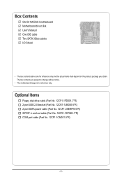
...-0*R) S/PDIF in and out cable (Part No. 12CR1-1SPINO-1*R) COM port cable (Part No. 12CF1-1CM001-3*R) - 6 - The box contents are for reference only. Box Contents GA-G41M-ES2H motherboard Motherboard driver disk User's Manual One IDE cable Two SATA 3Gb/s cables I/O Shield • The box contents above are subject to change without notice. • The...
...-0*R) S/PDIF in and out cable (Part No. 12CR1-1SPINO-1*R) COM port cable (Part No. 12CF1-1CM001-3*R) - 6 - The box contents are for reference only. Box Contents GA-G41M-ES2H motherboard Motherboard driver disk User's Manual One IDE cable Two SATA 3Gb/s cables I/O Shield • The box contents above are subject to change without notice. • The...
Manual
Page 7
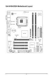
GA-G41M-ES2H Motherboard Layout KB_MS ATX_12V CPU_FAN IT8720 VGA_DVI HDMI R_USB Level Shifter Level Shifter LGA775 USB_LAN AUDIO BATTERY F_AUDIO CLR_CMOS Intel® G41 IDE ATX GA-G41M-ES2H DDR2_1 DDR2_2 PCIEX4 RTL8110SC PCI1 PCI2 CODEC PCI3 CD_IN SPDIF_IO COMA FDD SYS_FAN Intel® ICH7 B_BIOS M_BIOS SATA2_3 F_USB2 F_USB1 SATA2_2 SATA2_1 SATA2_0 F_PANEL - 7 -
GA-G41M-ES2H Motherboard Layout KB_MS ATX_12V CPU_FAN IT8720 VGA_DVI HDMI R_USB Level Shifter Level Shifter LGA775 USB_LAN AUDIO BATTERY F_AUDIO CLR_CMOS Intel® G41 IDE ATX GA-G41M-ES2H DDR2_1 DDR2_2 PCIEX4 RTL8110SC PCI1 PCI2 CODEC PCI3 CD_IN SPDIF_IO COMA FDD SYS_FAN Intel® ICH7 B_BIOS M_BIOS SATA2_3 F_USB2 F_USB1 SATA2_2 SATA2_1 SATA2_0 F_PANEL - 7 -
Manual
Page 9
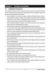
... power by your hands dry and first touch a metal object to eliminate static electricity. • Prior to installing the motherboard, please have a problem related to wear an electrostatic discharge (ESD) wrist strap when handling electronic com- Chapter 1 Hardware Installation 1-1 Installation... Precautions The motherboard contains numerous delicate electronic circuits and components which can lead to damage to system components as well as physical harm to ...
... power by your hands dry and first touch a metal object to eliminate static electricity. • Prior to installing the motherboard, please have a problem related to wear an electrostatic discharge (ESD) wrist strap when handling electronic com- Chapter 1 Hardware Installation 1-1 Installation... Precautions The motherboard contains numerous delicate electronic circuits and components which can lead to damage to system components as well as physical harm to ...
Manual
Page 12
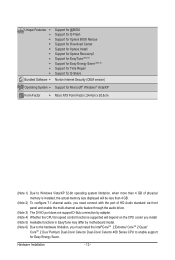
... 4) Whether the CPU fan speed control function is supported will depend on the CPU cooler you install. (Note 5) Available functions in EasyTune may differ by motherboard model. (Note 6) Due to the hardware limitation, you must install the Intel®CoreTM 2 Extreme/ CoreTM 2 Quad/ CoreTM 2 Duo/ Pentium Dual-Core/ Celeron Dual-Core...
... 4) Whether the CPU fan speed control function is supported will depend on the CPU cooler you install. (Note 5) Available functions in EasyTune may differ by motherboard model. (Note 6) Due to the hardware limitation, you must install the Intel®CoreTM 2 Extreme/ CoreTM 2 Quad/ CoreTM 2 Duo/ Pentium Dual-Core/ Celeron Dual-Core...
Manual
Page 13
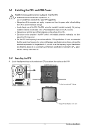
... socket.) • Apply an even and thin layer of thermal grease on the computer if the CPU cooler is not recommended that the motherboard supports the CPU. (Go to GIGABYTE's website for the peripherals. If you begin to install the CPU: • Make sure that the system bus frequency be set the... do so according to your hardware specifications including the CPU, graphics card, memory, hard drive, etc. 1-3-1 Installing the CPU A. Locate the alignment keys on the motherboard CPU socket and the notches on the CPU - 13 -
... socket.) • Apply an even and thin layer of thermal grease on the computer if the CPU cooler is not recommended that the motherboard supports the CPU. (Go to GIGABYTE's website for the peripherals. If you begin to install the CPU: • Make sure that the system bus frequency be set the... do so according to your hardware specifications including the CPU, graphics card, memory, hard drive, etc. 1-3-1 Installing the CPU A. Locate the alignment keys on the motherboard CPU socket and the notches on the CPU - 13 -

Manual
Page 14
..., always replace the protective socket cover when the CPU is properly inserted, replace the load plate and push the CPU socket lever back into the motherboard CPU socket. B. Align the CPU pin one marking (triangle) with the pin one corner of the CPU socket (or you may align the CPU notches...
..., always replace the protective socket cover when the CPU is properly inserted, replace the load plate and push the CPU socket lever back into the motherboard CPU socket. B. Align the CPU pin one marking (triangle) with the pin one corner of the CPU socket (or you may align the CPU notches...
Manual
Page 15
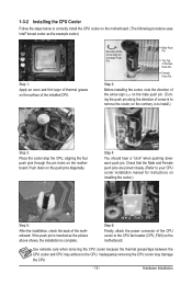
... installing the cooler, note the direction of the arrow sign on the male push pin. (Turning the push pin along the direction of the motherboard. Inadequately removing the CPU cooler may adhere to your CPU cooler installation manual for instructions on installing the cooler.) Step 5: After the installation,...surface of the CPU cooler to install.) Step 3: Place the cooler atop the CPU, aligning the four push pins through the pin holes on the motherboard. Step 4: You should hear a "click" when pushing down on the push pins diagonally. Push down each push pin. 1-3-2 Installing the CPU ...
... installing the cooler, note the direction of the arrow sign on the male push pin. (Turning the push pin along the direction of the motherboard. Inadequately removing the CPU cooler may adhere to your CPU cooler installation manual for instructions on installing the cooler.) Step 5: After the installation,...surface of the CPU cooler to install.) Step 3: Place the cooler atop the CPU, aligning the four push pins through the pin holes on the motherboard. Step 4: You should hear a "click" when pushing down on the push pins diagonally. Push down each push pin. 1-3-2 Installing the CPU ...
Manual
Page 16
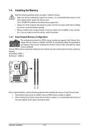
...: Channel 0: DDR2_1 Channel 1: DDR2_2 DDR2_1 DDR2_2 Due to insert the memory, switch the direction. 1-4-1 Dual Channel Memory Configuration This motherboard provides four DDR2 memory sockets and supports Dual Channel Technology. Enabling Dual Channel memory mode will automatically detect the specifications and capacity of... the same capacity, brand, speed, and chips be used . (Go to GIGABYTE's website for the latest memory support list.) • Always turn off the computer and unplug the power cord from the power outlet...
...: Channel 0: DDR2_1 Channel 1: DDR2_2 DDR2_1 DDR2_2 Due to insert the memory, switch the direction. 1-4-1 Dual Channel Memory Configuration This motherboard provides four DDR2 memory sockets and supports Dual Channel Technology. Enabling Dual Channel memory mode will automatically detect the specifications and capacity of... the same capacity, brand, speed, and chips be used . (Go to GIGABYTE's website for the latest memory support list.) • Always turn off the computer and unplug the power cord from the power outlet...

Manual
Page 17
... DIMM A DDR2 memory module has a notch, so it vertically into place when the memory module is securely inserted. - 17 - Place the memory module on this motherboard. Hardware Installation 1-4-2 Installing a Memory Before installing a memory module, make sure to turn off the computer and unplug the power cord from the power outlet to...
... DIMM A DDR2 memory module has a notch, so it vertically into place when the memory module is securely inserted. - 17 - Place the memory module on this motherboard. Hardware Installation 1-4-2 Installing a Memory Before installing a memory module, make sure to turn off the computer and unplug the power cord from the power outlet to...
Manual
Page 18
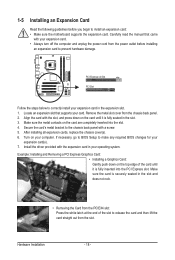
... with your computer. 1-5 Installing an Expansion Card Read the following guidelines before installing an expansion card to install an expansion card: • Make sure the motherboard supports the expansion card. Carefully read the manual that supports your expansion card(s). 7. After installing all expansion cards, replace the chassis cover(s). 6. Make sure the...
... with your computer. 1-5 Installing an Expansion Card Read the following guidelines before installing an expansion card to install an expansion card: • Make sure the motherboard supports the expansion card. Carefully read the manual that supports your expansion card(s). 7. After installing all expansion cards, replace the chassis cover(s). 6. Make sure the...
Manual
Page 19
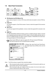
...) provides an all-digital audio/video interface to prevent an electrical short inside the cable connector. - 19 - Do not rock it straight out from the motherboard. • When removing the cable, pull it side to side to transmit the uncompressed audio/video signals and is HDCP compliant. 1-6 Back Panel Connectors (Note...
...) provides an all-digital audio/video interface to prevent an electrical short inside the cable connector. - 19 - Do not rock it straight out from the motherboard. • When removing the cable, pull it side to side to transmit the uncompressed audio/video signals and is HDCP compliant. 1-6 Back Panel Connectors (Note...
Manual
Page 20
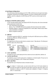
... 8.0 or later (Note: Please ensure Hard ware Acceleration is occurring Line In Jack (Blue) The default line in a 4/5.1-channel audio configuration. Dual Display Configurations: This motherboard provides three display ports, DVI-D, HDMI, and D-Sub ports and supports dual-display configurations. Microphones must be connected to 1 Gbps data rate. A. Refer to the...
... 8.0 or later (Note: Please ensure Hard ware Acceleration is occurring Line In Jack (Blue) The default line in a 4/5.1-channel audio configuration. Dual Display Configurations: This motherboard provides three display ports, DVI-D, HDMI, and D-Sub ports and supports dual-display configurations. Microphones must be connected to 1 Gbps data rate. A. Refer to the...

Manual
Page 21
... 6) IDE 7) SATA2_0/1/2/3 8) F_PANEL 9) 10) 11) 12) 13) 14) 15) F_AUDIO CD_IN SPDIF_IO F_USB1/F_USB2 COMA CLR_CMOS BATTERY Read the following guidelines before turning on the motherboard. - 21 -
... 6) IDE 7) SATA2_0/1/2/3 8) F_PANEL 9) 10) 11) 12) 13) 14) 15) F_AUDIO CD_IN SPDIF_IO F_USB1/F_USB2 COMA CLR_CMOS BATTERY Read the following guidelines before turning on the motherboard. - 21 -

Manual
Page 22
...supply providing a 2x4 12V and a 2x12 power connector, remove the protective covers from the 12V power connector and the main power connector on the motherboard. If the 12V power connector is not connected, the computer will not start. • To meet expansion requirements, it is turned off and... all the components on the motherboard. Connect the power supply cable to the CPU. Before connecting the power connector, first make sure the power supply is recommended that a power...
...supply providing a 2x4 12V and a 2x12 power connector, remove the protective covers from the 12V power connector and the main power connector on the motherboard. If the 12V power connector is not connected, the computer will not start. • To meet expansion requirements, it is turned off and... all the components on the motherboard. Connect the power supply cable to the CPU. Before connecting the power connector, first make sure the power supply is recommended that a power...
Manual
Page 23
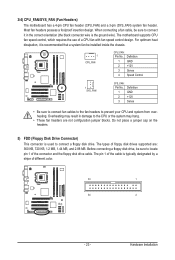
... connect it is the ground wire). The pin 1 of the cable is used to locate pin 1 of different color. 33 1 34 2 - 23 - The motherboard supports CPU fan speed control, which requires the use of floppy disk drives supported are not configuration jumper blocks. Do not place a jumper cap on... Overheating may hang. • These fan headers are : 360 KB, 720 KB, 1.2 MB, 1.44 MB, and 2.88 MB. 3/4) CPU_FAN/SYS_FAN (Fan Headers) The motherboard has a 4-pin CPU fan header (CPU_FAN) and a 3-pin (SYS_FAN) system fan header. The types of a CPU fan with fan speed control design.
... connect it is the ground wire). The pin 1 of the cable is used to locate pin 1 of different color. 33 1 34 2 - 23 - The motherboard supports CPU fan speed control, which requires the use of floppy disk drives supported are not configuration jumper blocks. Do not place a jumper cap on... Overheating may hang. • These fan headers are : 360 KB, 720 KB, 1.2 MB, 1.44 MB, and 2.88 MB. 3/4) CPU_FAN/SYS_FAN (Fan Headers) The motherboard has a 4-pin CPU fan header (CPU_FAN) and a 3-pin (SYS_FAN) system fan header. The types of a CPU fan with fan speed control design.
Manual
Page 26
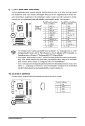
You may connect the audio cable that has separated connectors on both of the motherboard header. Incorrect connection between the module connector and the motherboard header will be present on each wire instead of a single plug. Definition 1 CD-L 2 GND 3 GND 4 CD-R Hardware Installation - 26 - 9) F_AUDIO (Front Panel Audio Header) The ...
You may connect the audio cable that has separated connectors on both of the motherboard header. Incorrect connection between the module connector and the motherboard header will be present on each wire instead of a single plug. Definition 1 CD-L 2 GND 3 GND 4 CD-R Hardware Installation - 26 - 9) F_AUDIO (Front Panel Audio Header) The ...


