
Manual
Page 1
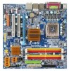
GA-G33M-DS2R/ GA-G33M-S2 LGA775 socket motherboard for Intel® CoreTM processor family/ Intel® Pentium® processor family/Intel® Celeron® processor family User's Manual Rev. 1003 12ME-G33MD2R-1003R * The WEEE marking on the product indicates this product must not be disposed of with user's other household waste and must be handed over to a designated collection point for the recycling of waste electrical and electronic equipment!! * The WEEE marking applies only in European Union's member states.
GA-G33M-DS2R/ GA-G33M-S2 LGA775 socket motherboard for Intel® CoreTM processor family/ Intel® Pentium® processor family/Intel® Celeron® processor family User's Manual Rev. 1003 12ME-G33MD2R-1003R * The WEEE marking on the product indicates this product must not be disposed of with user's other household waste and must be handed over to a designated collection point for the recycling of waste electrical and electronic equipment!! * The WEEE marking applies only in European Union's member states.

Manual
Page 4
... Guide page on your motherboard revision before updating motherboard BIOS, drivers, or when looking for technical information. Check your motherboard looks like this product, GIGABYTE provides the following types of this manual are legally registered to the specifications and features in this manual may be made by any form or by GIGABYTE without GIGABYTE's prior written permission. All...
... Guide page on your motherboard revision before updating motherboard BIOS, drivers, or when looking for technical information. Check your motherboard looks like this product, GIGABYTE provides the following types of this manual are legally registered to the specifications and features in this manual may be made by any form or by GIGABYTE without GIGABYTE's prior written permission. All...
Manual
Page 7
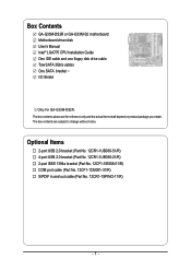
...-1IE008-01/R) COM port cable (Part No. 12CF1-1CM001-31/R) S/PDIF in and out cable (Part No. 12CR1-1SPINO-11/R) - 7 - Box Contents GA-G33M-DS2R or GA-G33M-S2 motherboard Motherboard driver disk User's Manual Intel® LGA775 CPU Installation Guide One IDE cable and one floppy disk drive cable Tow SATA 3Gb/s cables One SATA bracket I/O Shield...
...-1IE008-01/R) COM port cable (Part No. 12CF1-1CM001-31/R) S/PDIF in and out cable (Part No. 12CR1-1SPINO-11/R) - 7 - Box Contents GA-G33M-DS2R or GA-G33M-S2 motherboard Motherboard driver disk User's Manual Intel® LGA775 CPU Installation Guide One IDE cable and one floppy disk drive cable Tow SATA 3Gb/s cables One SATA bracket I/O Shield...

Manual
Page 11
...Installation Prior to installation, carefully read the user's manual and follow these procedures: • Prior to installation, do not remove or break motherboard S/N (Serial Number) sticker or warranty sticker provided by unplugging the power cord from the motherboard, make sure the power supply has been turned ... high-temperature environment. • Turning on the power, make sure they are connected tightly and securely. • When handling the motherboard, avoid touching any metal leads or connectors. • It is best to the use of electrostatic discharge (ESD). These stickers are...
...Installation Prior to installation, carefully read the user's manual and follow these procedures: • Prior to installation, do not remove or break motherboard S/N (Serial Number) sticker or warranty sticker provided by unplugging the power cord from the motherboard, make sure the power supply has been turned ... high-temperature environment. • Turning on the power, make sure they are connected tightly and securely. • When handling the motherboard, avoid touching any metal leads or connectors. • It is best to the use of electrostatic discharge (ESD). These stickers are...

Manual
Page 17
...CPU. Hardware Installation Push down each push pin. Check that the Male and Female push pins are joined closely. (Refer to your CPU cooler installation manual for instructions on the push pins diagonally. If the push pin is inserted as the example cooler.) Step 1: Apply an even and thin layer ...cooler, on the contrary, is to install.) Step 3: Place the cooler atop the CPU, aligning the four push pins through the pin holes on the motherboard. Use extreme care when removing the CPU cooler because the thermal grease/tape between the CPU cooler and CPU may damage the CPU. - 17 - English...
...CPU. Hardware Installation Push down each push pin. Check that the Male and Female push pins are joined closely. (Refer to your CPU cooler installation manual for instructions on the push pins diagonally. If the push pin is inserted as the example cooler.) Step 1: Apply an even and thin layer ...cooler, on the contrary, is to install.) Step 3: Place the cooler atop the CPU, aligning the four push pins through the pin holes on the motherboard. Use extreme care when removing the CPU cooler because the thermal grease/tape between the CPU cooler and CPU may damage the CPU. - 17 - English...
Manual
Page 20
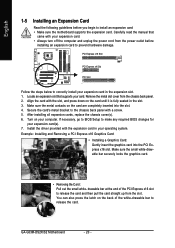
Remove the metal slot cover from the slot. After installing all expansion cards, replace the chassis cover(s). 6. GA-G33M-DS2R/S2 Motherboard - 20 - If necessary, go to BIOS Setup to make any required BIOS changes for your expansion card in the slot. 3. drawable bar... and Removing a PCI Express x16 Graphics Card: • Installing a Graphics Card: Gently insert the graphics card into the slot. 4. Carefully read the manual that supports your computer. PCI Express x16 Slot PCI Express x4 Slot PCI Slot Follow the steps below to correctly install your expansion card(s). 7.
Remove the metal slot cover from the slot. After installing all expansion cards, replace the chassis cover(s). 6. GA-G33M-DS2R/S2 Motherboard - 20 - If necessary, go to BIOS Setup to make any required BIOS changes for your expansion card in the slot. 3. drawable bar... and Removing a PCI Express x16 Graphics Card: • Installing a Graphics Card: Gently insert the graphics card into the slot. 4. Carefully read the manual that supports your computer. PCI Express x16 Slot PCI Express x4 Slot PCI Slot Follow the steps below to correctly install your expansion card(s). 7.

Manual
Page 34
... to remove the jumper cap from the jumper. Failure to do so may cause damage to the motherboard. • After system restart, go to BIOS Setup to load factory defaults (select Load Optimized Defaults) or manually configure the BIOS settings (refer to touch the two pins for BIOS configurations). Open: Normal Short... before turning on the two pins to temporarily short the two pins or use a metal object like a screwdriver to Chapter 2, "BIOS Setup," for a few seconds. GA-G33M-DS2R/S2 Motherboard - 34 -
... to remove the jumper cap from the jumper. Failure to do so may cause damage to the motherboard. • After system restart, go to BIOS Setup to load factory defaults (select Load Optimized Defaults) or manually configure the BIOS settings (refer to touch the two pins for BIOS configurations). Open: Normal Short... before turning on the two pins to temporarily short the two pins or use a metal object like a screwdriver to Chapter 2, "BIOS Setup," for a few seconds. GA-G33M-DS2R/S2 Motherboard - 34 -

Manual
Page 40
... (default), Drive A. If you wish to enter the parameters manually, refer to determine whether the system will not stop for an error during the POST. Options are determined by the BIOS POST. Halt on Allows you to the information on the system. GA-G33M-DS2R/S2 Motherboard - 40 - Base Memory Also called conventional memory. Head...
... (default), Drive A. If you wish to enter the parameters manually, refer to determine whether the system will not stop for an error during the POST. Options are determined by the BIOS POST. Halt on Allows you to the information on the system. GA-G33M-DS2R/S2 Motherboard - 40 - Base Memory Also called conventional memory. Head...

Manual
Page 54
... Host Frequency (Mhz) and System Memory Multiplier settings. the second is enabled. Manual allows all voltage control items below to be set this item to 333 MHz. FSB OverVoltage Control Allows you to set the PCIe clock frequency. GA-G33M-DS2R/S2 Motherboard - 54 - Options are dependent on CPU FSB. Note: Increasing memory voltage may...
... Host Frequency (Mhz) and System Memory Multiplier settings. the second is enabled. Manual allows all voltage control items below to be set this item to 333 MHz. FSB OverVoltage Control Allows you to set the PCIe clock frequency. GA-G33M-DS2R/S2 Motherboard - 54 - Options are dependent on CPU FSB. Note: Increasing memory voltage may...

Manual
Page 61
Drivers Installation English 3-4 Hardware Information This page provides information about the hardware devices on this motherboard. 3-5 Contact Us Check the contacts information of the GIGABYTE headquarter in Taiwan and the overseas branch offices on the last page of this manual. - 61 -
Drivers Installation English 3-4 Hardware Information This page provides information about the hardware devices on this motherboard. 3-5 Contact Us Check the contacts information of the GIGABYTE headquarter in Taiwan and the overseas branch offices on the last page of this manual. - 61 -

Manual
Page 72
...the BIOS update file (e.g. g33mds2r. f1) obtained from GIGABYTE's website and follow the instructions in an unbootable system. • If the BIOS update file for your motherboard model. Select Load Optimized Defaults and press to load BIOS defaults. 3. GA-G33M-DS2R/S2 Motherboard - 72 - Upon completion, restart your system. &#.... English Step 3: First make sure the model name on the screen is not present on the @BIOS server site, please manually download the BIOS update file from the Internet or through other source. Updating the BIOS with an incorrect BIOS file could result ...
...the BIOS update file (e.g. g33mds2r. f1) obtained from GIGABYTE's website and follow the instructions in an unbootable system. • If the BIOS update file for your motherboard model. Select Load Optimized Defaults and press to load BIOS defaults. 3. GA-G33M-DS2R/S2 Motherboard - 72 - Upon completion, restart your system. &#.... English Step 3: First make sure the model name on the screen is not present on the @BIOS server site, please manually download the BIOS update file from the Internet or through other source. Updating the BIOS with an incorrect BIOS file could result ...
Manual
Page 82
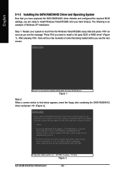
... disk controllers for use with Windows, including those for which you have a device support disk from a mass storage device manufacturer, press S. * If you need to manually specify an adapter. Figure 1 Step 2: When a screen similar to that you have chosen to install a third party SCSI or RAID driver. After pressing , there will... onto your system to install a 3rd party SCSI or RAID driver" (Figure 1). Step 1: Restart your hard drive(s). S=Specify Additional Device ENTER=Continue F3=Exit Figure 2 GA-G33M-DS2R/S2 Motherboard - 82 -
... disk controllers for use with Windows, including those for which you have a device support disk from a mass storage device manufacturer, press S. * If you need to manually specify an adapter. Figure 1 Step 2: When a screen similar to that you have chosen to install a third party SCSI or RAID driver. After pressing , there will... onto your system to install a 3rd party SCSI or RAID driver" (Figure 1). Step 1: Restart your hard drive(s). S=Specify Additional Device ENTER=Continue F3=Exit Figure 2 GA-G33M-DS2R/S2 Motherboard - 82 -

Manual
Page 85
...users can have an Internet chat, make sure the "Microsoft UAA Bus driver for High Defintion Audio" has been installed from the motherboard driver disk and your operating system has been updated with the latest Service Pack for multi-channel speaker configurations. • 2 channel ... 5-2 Configuring Audio Input and Output 5-2-1 Configuring 2/4/5.1/7.1-Channel Audio The motherboard provides six audio jacks on the back panel which support 2/4/5.1/7.1-channel audio. Side Speaker Out Mic In For example, in jack and manually configure the jack for each jack through the audio driver. all ...
...users can have an Internet chat, make sure the "Microsoft UAA Bus driver for High Defintion Audio" has been installed from the motherboard driver disk and your operating system has been updated with the latest Service Pack for multi-channel speaker configurations. • 2 channel ... 5-2 Configuring Audio Input and Output 5-2-1 Configuring 2/4/5.1/7.1-Channel Audio The motherboard provides six audio jacks on the back panel which support 2/4/5.1/7.1-channel audio. Side Speaker Out Mic In For example, in jack and manually configure the jack for each jack through the audio driver. all ...


