Manual
Page 3
...exclusively licensed to the specifications and features in the use of GIGABYTE. Example: Copyright © 2008 GIGA-BYTE TECHNOLOGY CO., LTD. is 1.0. sive global distributor of the product, read the Quick Installation Guide included with the product. „ For detailed product ...information, carefully read the User's Manual. „ For instructions on how to use GIGABYTE's unique features, read or download the information on/from...
...exclusively licensed to the specifications and features in the use of GIGABYTE. Example: Copyright © 2008 GIGA-BYTE TECHNOLOGY CO., LTD. is 1.0. sive global distributor of the product, read the Quick Installation Guide included with the product. „ For detailed product ...information, carefully read the User's Manual. „ For instructions on how to use GIGABYTE's unique features, read or download the information on/from...
Manual
Page 4
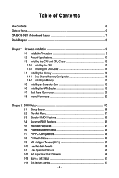
Table of Contents Box Contents ...6 OptionalItems ...6 GA-EX38-DS4 Motherboard Layout 7 Block Diagram ...8 Chapter 1 Hardware Installation 9 1-1 Installation Precautions 9 1-2 Product Specifications 10 1-3 Installing the CPU and CPU Cooler 13 1-3-1 Installing the CPU 13 1-3-2 Installing the CPU Cooler 15 1-4 Installing the Memory 16 1-4-1 Dual Channel Memory Configuration 16 1-4-2 Installing a Memory 17 1-5 Installing an Expansion Card 18 1-6 Installing the SATA Bracket 19 1-7 Back Panel Connectors 20...
Table of Contents Box Contents ...6 OptionalItems ...6 GA-EX38-DS4 Motherboard Layout 7 Block Diagram ...8 Chapter 1 Hardware Installation 9 1-1 Installation Precautions 9 1-2 Product Specifications 10 1-3 Installing the CPU and CPU Cooler 13 1-3-1 Installing the CPU 13 1-3-2 Installing the CPU Cooler 15 1-4 Installing the Memory 16 1-4-1 Dual Channel Memory Configuration 16 1-4-2 Installing a Memory 17 1-5 Installing an Expansion Card 18 1-6 Installing the SATA Bracket 19 1-7 Back Panel Connectors 20...

Manual
Page 5
Chapter 3 Drivers Installation 59 3-1 Installing Chipset Drivers 59 3-2 SoftwareApplications 60 3-3 Driver CD Information 60 3-4 Hardware Information 61 3-5 Contact Us ...61 Chapter 4 Unique Features 63 4-1 Xpress ... Configuring Intel® ICH9R SATA Controllers 77 5-1-2 Making a SATA RAID/AHCI Driver Diskette 83 5-1-3 Installing the SATA RAID/AHCI Driver and Operating System 84 5-2 ConfiguringAudio Input and Output 89 5-2-1 Configuring 2/4/5.1/7.1-Channel Audio 89 5-2-2 Installing the S/PDIF In Cable (Optional 91 5-2-3 Enabling the DTS (Digital Theater Systems) Function 93 5-2-4...
Chapter 3 Drivers Installation 59 3-1 Installing Chipset Drivers 59 3-2 SoftwareApplications 60 3-3 Driver CD Information 60 3-4 Hardware Information 61 3-5 Contact Us ...61 Chapter 4 Unique Features 63 4-1 Xpress ... Configuring Intel® ICH9R SATA Controllers 77 5-1-2 Making a SATA RAID/AHCI Driver Diskette 83 5-1-3 Installing the SATA RAID/AHCI Driver and Operating System 84 5-2 ConfiguringAudio Input and Output 89 5-2-1 Configuring 2/4/5.1/7.1-Channel Audio 89 5-2-2 Installing the S/PDIF In Cable (Optional 91 5-2-3 Enabling the DTS (Digital Theater Systems) Function 93 5-2-4...
Manual
Page 6
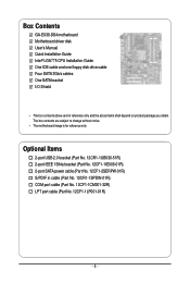
...-01R) COM port cable (Part No. 12CF1-1CM001-32R) LPT port cable (Part No. 12CF1-1LP001-01R) - 6 - Box Contents GA-EX38-DS4 motherboard Motherboard driver disk User's Manual Quick Installation Guide Intel® LGA775 CPU Installation Guide One IDE cable and one floppy disk drive cable Four SATA 3Gb/s cables One SATA bracket I/O Shield •...
...-01R) COM port cable (Part No. 12CF1-1CM001-32R) LPT port cable (Part No. 12CF1-1LP001-01R) - 6 - Box Contents GA-EX38-DS4 motherboard Motherboard driver disk User's Manual Quick Installation Guide Intel® LGA775 CPU Installation Guide One IDE cable and one floppy disk drive cable Four SATA 3Gb/s cables One SATA bracket I/O Shield •...

Manual
Page 9
...8226; Before using the product, please verify that all cables and power connectors of your dealer. Hardware Installation Chapter 1 Hardware Installation 1-1 Installation Precautions The motherboard contains numerous delicate electronic circuits and components which can lead to damage to system components...when handling electronic components such as a result of the product, please consult a certified computer technician. - 9 - Prior to installation, carefully read the user's manual and follow these procedures: • Prior to the use of electrostatic discharge (ESD). These stickers...
...8226; Before using the product, please verify that all cables and power connectors of your dealer. Hardware Installation Chapter 1 Hardware Installation 1-1 Installation Precautions The motherboard contains numerous delicate electronic circuits and components which can lead to damage to system components...when handling electronic components such as a result of the product, please consult a certified computer technician. - 9 - Prior to installation, carefully read the user's manual and follow these procedures: • Prior to the use of electrostatic discharge (ESD). These stickers...

Manual
Page 11
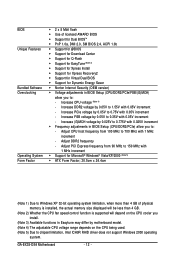
...; CPU/System/Power fan speed detection Š CPU overheating warning Š CPU/System/Power fan fail warning Š CPU fan speed control (Note 2) - 11 - Hardware Installation
...; CPU/System/Power fan speed detection Š CPU overheating warning Š CPU/System/Power fan fail warning Š CPU fan speed control (Note 2) - 11 - Hardware Installation
Manual
Page 12
GA-EX38-DS4 Motherboard - 12 - Increase FSB voltage by 0.05V to 0.35V with... Features Bundled Software Overclocking Operating System Form Factor Š 2 x 8 Mbit flash Š Use of physical memory is installed, the actual memory size displayed will be less than 4 GB of licensed AWARD BIOS Š Support for Dual BIOSTM &#...138; Support for Download Center Š Support for Q-Flash Š Support for EasyTune (Note 3) Š Support for Xpress Install Š Support for Xpress Recovery2 Š Support for Virtual Dual BIOS Š Support for Dynamic Energy Saver Š Norton Internet...
GA-EX38-DS4 Motherboard - 12 - Increase FSB voltage by 0.05V to 0.35V with... Features Bundled Software Overclocking Operating System Form Factor Š 2 x 8 Mbit flash Š Use of physical memory is installed, the actual memory size displayed will be less than 4 GB of licensed AWARD BIOS Š Support for Dual BIOSTM &#...138; Support for Download Center Š Support for Q-Flash Š Support for EasyTune (Note 3) Š Support for Xpress Install Š Support for Xpress Recovery2 Š Support for Virtual Dual BIOS Š Support for Dynamic Energy Saver Š Norton Internet...

Manual
Page 13
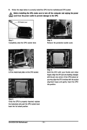
... you begin to install the CPU: • Make sure that the system bus frequency be inserted if oriented incorrectly. (Or you may occur. • Set the CPU host frequency in accordance with the CPU specifications. mended that the motherboard supports the CPU. (Go to GIGABYTE's website for the... peripherals. It is not installed, otherwise overheating and damage of the CPU may locate the notches on both sides of the CPU and alignment keys on...
... you begin to install the CPU: • Make sure that the system bus frequency be inserted if oriented incorrectly. (Or you may occur. • Set the CPU host frequency in accordance with the CPU specifications. mended that the motherboard supports the CPU. (Go to GIGABYTE's website for the... peripherals. It is not installed, otherwise overheating and damage of the CPU may locate the notches on both sides of the CPU and alignment keys on...
Manual
Page 14
... CPU notches with your thumb and index fingers. CPU Socket Lever Step 1: Completely raise the CPU socket lever. Step 2: Remove the protective socket cover. GA-EX38-DS4 Motherboard - 14 - Before installing the CPU, make sure to turn off the computer and unplug the power cord from the power outlet to prevent damage to correctly...
... CPU notches with your thumb and index fingers. CPU Socket Lever Step 1: Completely raise the CPU socket lever. Step 2: Remove the protective socket cover. GA-EX38-DS4 Motherboard - 14 - Before installing the CPU, make sure to turn off the computer and unplug the power cord from the power outlet to prevent damage to correctly...

Manual
Page 15
... motherboard. Direction of the Arrow Sign on the Male Push Pin Male Push Pin The Top of Female Push Pin Female Push Pin Step 2: Before installing the cooler, note the direction of the arrow sign on the male push pin. (Turning the push pin along the direction of the... on the push pins diagonally. Check that the Male and Female push pins are joined closely. (Refer to your CPU cooler installation manual for instructions on installing the cooler.) Step 5: After the installation, check the back of the CPU cooler to remove the cooler, on the motherboard. If the push pin is inserted...
... motherboard. Direction of the Arrow Sign on the Male Push Pin Male Push Pin The Top of Female Push Pin Female Push Pin Step 2: Before installing the cooler, note the direction of the arrow sign on the male push pin. (Turning the push pin along the direction of the... on the push pins diagonally. Check that the Male and Female push pins are joined closely. (Refer to your CPU cooler installation manual for instructions on installing the cooler.) Step 5: After the installation, check the back of the CPU cooler to remove the cooler, on the motherboard. If the push pin is inserted...
Manual
Page 16
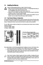
...Dual Channel mode with two or four memory modules, it is installed, the BIOS will automatically detect the specifications and capacity of the same capacity, brand, speed, and chips be used . (Go to GIGABYTE's website for optimum performance. After the memory is recommended that... This motherboard provides four DDR2 memory sockets and supports Dual Channel Technology. GA-EX38-DS4 Motherboard - 16 - Intel® Flex Memory Technology offers greater flexibility to upgrade by allowing different memory sizes to install the memory: • Make sure that memory of different capacity and...
...Dual Channel mode with two or four memory modules, it is installed, the BIOS will automatically detect the specifications and capacity of the same capacity, brand, speed, and chips be used . (Go to GIGABYTE's website for optimum performance. After the memory is recommended that... This motherboard provides four DDR2 memory sockets and supports Dual Channel Technology. GA-EX38-DS4 Motherboard - 16 - Intel® Flex Memory Technology offers greater flexibility to upgrade by allowing different memory sizes to install the memory: • Make sure that memory of different capacity and...

Manual
Page 17
... DIMMs on the socket. Step 1: Note the orientation of the memory socket. Follow the steps below to correctly install your fingers on the memory and insert it can only fit in the memory sockets. Place the memory module on this motherboard. Notch DDR2 DIMM... A DDR2 memory module has a notch, so it vertically into place when the memory module is securely inserted. - 17 - Hardware Installation Spread the retaining clips at both ends of the memory module. As indicated in the picture on the left, place your memory modules in one...
... DIMMs on the socket. Step 1: Note the orientation of the memory socket. Follow the steps below to correctly install your fingers on the memory and insert it can only fit in the memory sockets. Place the memory module on this motherboard. Notch DDR2 DIMM... A DDR2 memory module has a notch, so it vertically into place when the memory module is securely inserted. - 17 - Hardware Installation Spread the retaining clips at both ends of the memory module. As indicated in the picture on the left, place your memory modules in one...
Manual
Page 18
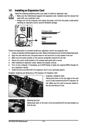
... on the top edge of the card until it is securely seated in the slot. 3. GA-EX38-DS4 Motherboard - 18 - Make sure the card is fully inserted into the slot. 4. 1-5 Installing an Expansion Card Read the following guidelines before installing an expansion card to prevent hardware damage. Carefully read the manual that supports your expansion...
... on the top edge of the card until it is securely seated in the slot. 3. GA-EX38-DS4 Motherboard - 18 - Make sure the card is fully inserted into the slot. 4. 1-5 Installing an Expansion Card Read the following guidelines before installing an expansion card to prevent hardware damage. Carefully read the manual that supports your expansion...

Manual
Page 19
... cable securely into to the power supply. Step 2: Connect the SATA cable from the bracket SATA signal cable into the corresponding connectors when installing. Then attach the SATA power cable to connect the SATA signal cable. Before connecting the SATA signal cable, make sure to turn off... by expanding the internal SATA port(s) to the chassis back panel. • Turn off the power of the external enclosure. - 19 - 1-6 Installing the SATA Bracket The SATA bracket allows you only need to the power connector on the bracket. the external SATA con- Follow the steps below...
... cable securely into to the power supply. Step 2: Connect the SATA cable from the bracket SATA signal cable into the corresponding connectors when installing. Then attach the SATA power cable to connect the SATA signal cable. Before connecting the SATA signal cable, make sure to turn off... by expanding the internal SATA port(s) to the chassis back panel. • Turn off the power of the external enclosure. - 19 - 1-6 Installing the SATA Bracket The SATA bracket allows you only need to the power connector on the bracket. the external SATA con- Follow the steps below...

Manual
Page 21
... audio jack to connect center/subwoofer speakers in Chapter 5, "Configuring 2/4/5.1/7.1-Channel Audio." - 21 - Line In Jack (Blue) The default line in a 4/5.1/7.1-channel audio configuration. Hardware Installation This jack can be connected to this audio jack for line in jack ( ). In addition to the default speakers settings, the ~ audio jacks can be...
... audio jack to connect center/subwoofer speakers in Chapter 5, "Configuring 2/4/5.1/7.1-Channel Audio." - 21 - Line In Jack (Blue) The default line in a 4/5.1/7.1-channel audio configuration. Hardware Installation This jack can be connected to this audio jack for line in jack ( ). In addition to the default speakers settings, the ~ audio jacks can be...

Manual
Page 22
GA-EX38-DS4 Motherboard - 22 - Unplug the power cord from the power outlet to prevent damage to the devices. • After installing the device and before connecting external devices: • First make sure the device cable has been securely attached to turn off the devices and your ...) BAT Read the following guidelines before turning on the computer, make sure your devices are compliant with the connectors you wish to connect. • Before installing the devices, be sure to the connector on the motherboard.
GA-EX38-DS4 Motherboard - 22 - Unplug the power cord from the power outlet to prevent damage to the devices. • After installing the device and before connecting external devices: • First make sure the device cable has been securely attached to turn off the devices and your ...) BAT Read the following guidelines before turning on the computer, make sure your devices are compliant with the connectors you wish to connect. • Before installing the devices, be sure to the connector on the motherboard.

Manual
Page 23
...power connector. • The ATX_12V_2X power connector is recommended that a power supply that can supply enough stable power to all devices are properly installed. Do not insert the power supply cables into pins under the protective covers when using an Intel Extreme Edition CPU (130W). • To... meet expansion requirements, it is compatible with power supplies with 2x10 power connectors. Hardware Installation If the 12V power connector is not connected, the computer will not start. • Use of the power connector, the power supply ...
...power connector. • The ATX_12V_2X power connector is recommended that a power supply that can supply enough stable power to all devices are properly installed. Do not insert the power supply cables into pins under the protective covers when using an Intel Extreme Edition CPU (130W). • To... meet expansion requirements, it is compatible with power supplies with 2x10 power connectors. Hardware Installation If the 12V power connector is not connected, the computer will not start. • Use of the power connector, the power supply ...

Manual
Page 24
... wire is the ground wire. 1 Pin No. When connecting a fan cable, be installed inside the chassis. Definition 1 GND 2 +12V 3 NC • Be sure to connect fan cables to the fan headers to connect it in the correct orientation. GA-EX38-DS4 Motherboard - 24 - Most fans are designed with color-coded power connector wires. The...
... wire is the ground wire. 1 Pin No. When connecting a fan cable, be installed inside the chassis. Definition 1 GND 2 +12V 3 NC • Be sure to connect fan cables to the fan headers to connect it in the correct orientation. GA-EX38-DS4 Motherboard - 24 - Most fans are designed with color-coded power connector wires. The...

Manual
Page 25
... supported are: 360 KB, 720 KB, 1.2 MB, 1.44 MB, and 2.88 MB. The pin 1 of the cable is used to connect a floppy disk drive. Hardware Installation Before attaching the IDE cable, locate the foolproof groove on the connector. 7) FDD (Floppy Disk Drive Connector) This connector is typically designated by a stripe of...
... supported are: 360 KB, 720 KB, 1.2 MB, 1.44 MB, and 2.88 MB. The pin 1 of the cable is used to connect a floppy disk drive. Hardware Installation Before attaching the IDE cable, locate the foolproof groove on the connector. 7) FDD (Floppy Disk Drive Connector) This connector is typically designated by a stripe of...
Manual
Page 27
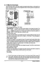
... below. If a problem is operating. A front panel module mainly consists of power switch, reset switch, power LED, hard drive activity LED, speaker and etc. Hardware Installation RESRES+ NC Hard Drive Reset Activity LED Switch • MSG (Message/Power/Sleep LED, Yellow): System Status LED Connects to the hard drive activity LED...
... below. If a problem is operating. A front panel module mainly consists of power switch, reset switch, power LED, hard drive activity LED, speaker and etc. Hardware Installation RESRES+ NC Hard Drive Reset Activity LED Switch • MSG (Message/Power/Sleep LED, Yellow): System Status LED Connects to the hard drive activity LED...


