
Manual
Page 4
... ...6 OptionalItems ...6 GA-EP45T-UD3P Motherboard Layout 7 Block Diagram ...8 Chapter 1 Hardware Installation 9 1-1 Installation Precautions 9 1-2 Product Specifications 10 1-3 Installing the CPU and CPU Cooler 13 1-3-1 Installing the CPU 13 1-3-2 Installing the CPU Cooler 15 1-4 Installing the Memory 16 1-4-1 Dual Channel Memory Configuration 16 1-4-2 Installing a Memory 17 1-5 Installing an Expansion Card 18 1-6 Installing the SATA Bracket 19 1-7 Back Panel Connectors 20 1-8 Internal Connectors 22 Chapter 2 BIOS Setup 35 2-1 Startup Screen 36 2-2 The Main Menu 37 2-3 MB...
... ...6 OptionalItems ...6 GA-EP45T-UD3P Motherboard Layout 7 Block Diagram ...8 Chapter 1 Hardware Installation 9 1-1 Installation Precautions 9 1-2 Product Specifications 10 1-3 Installing the CPU and CPU Cooler 13 1-3-1 Installing the CPU 13 1-3-2 Installing the CPU Cooler 15 1-4 Installing the Memory 16 1-4-1 Dual Channel Memory Configuration 16 1-4-2 Installing a Memory 17 1-5 Installing an Expansion Card 18 1-6 Installing the SATA Bracket 19 1-7 Back Panel Connectors 20 1-8 Internal Connectors 22 Chapter 2 BIOS Setup 35 2-1 Startup Screen 36 2-2 The Main Menu 37 2-3 MB...
Manual
Page 10
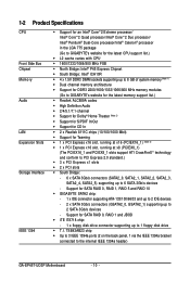
... 2 SATA 3Gb/s devices - Support for SATA RAID 0, RAID 1 and JBOD iTE IT8718 chip: - 1 x floppy disk drive connector supporting up to 1 floppy disk drive T.I. TSB43AB23 chip Up to 3 IEEE 1394a ports (2 on the back panel, 1 via the IEEE 1394a bracket connected to 6 SATA 3Gb/s devices - Support for SATA RAID 0, RAID 1, RAID 5 and RAID 10 GIGABYTE SATA2 chip: - 1 x IDE connector supporting ATA-133/100/66/33 and up to 2 IDE devices - 2 x SATA 3Gb/s connectors (GSATA2_0, GSATA2_1) supporting up to the internal IEEE 1394a header) GA-EP45T-UD3P Motherboard...
... 2 SATA 3Gb/s devices - Support for SATA RAID 0, RAID 1 and JBOD iTE IT8718 chip: - 1 x floppy disk drive connector supporting up to 1 floppy disk drive T.I. TSB43AB23 chip Up to 3 IEEE 1394a ports (2 on the back panel, 1 via the IEEE 1394a bracket connected to 6 SATA 3Gb/s devices - Support for SATA RAID 0, RAID 1, RAID 5 and RAID 10 GIGABYTE SATA2 chip: - 1 x IDE connector supporting ATA-133/100/66/33 and up to 2 IDE devices - 2 x SATA 3Gb/s connectors (GSATA2_0, GSATA2_1) supporting up to the internal IEEE 1394a header) GA-EP45T-UD3P Motherboard...
Manual
Page 16
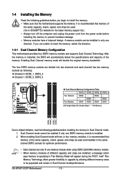
..., speed, and chips be used . (Go to GIGABYTE's website for optimum performance. • Each channel can be populated and remain in Dual Channel mode/performance. GA-EP45T-UD3P Motherboard - 16 - 1-4 Installing the Memory Read the following guidelines before installing the memory in Dual Channel mode. 1. Enabling Dual Channel memory mode will automatically detect the specifications and capacity of the same capacity, brand, speed, and chips be used and installed in the same colored DDR3 sockets for the latest memory support list.) • Always turn...
..., speed, and chips be used . (Go to GIGABYTE's website for optimum performance. • Each channel can be populated and remain in Dual Channel mode/performance. GA-EP45T-UD3P Motherboard - 16 - 1-4 Installing the Memory Read the following guidelines before installing the memory in Dual Channel mode. 1. Enabling Dual Channel memory mode will automatically detect the specifications and capacity of the same capacity, brand, speed, and chips be used and installed in the same colored DDR3 sockets for the latest memory support list.) • Always turn...

Manual
Page 36
... item on BIOS Setup settings. In Boot Menu, use the up hard drive data using the driver disk, the key can access Boot Menu again to change the first boot device setting as needed. : Q-FLASH Press the key to access the Q-Flash utility directly without having to set the first boot device without entering BIOS Setup. GA-EP45T-UD3P Motherboard - 36 - The POST Screen Award Modular BIOS v6.00PG, An Energy Star Ally Copyright (C) 1984-2008, Award Software, Inc. Note: The setting in Boot Menu is effective for subsequent access to access the Q-Flash utility in Boot Menu.
... item on BIOS Setup settings. In Boot Menu, use the up hard drive data using the driver disk, the key can access Boot Menu again to change the first boot device setting as needed. : Q-FLASH Press the key to access the Q-Flash utility directly without having to set the first boot device without entering BIOS Setup. GA-EP45T-UD3P Motherboard - 36 - The POST Screen Award Modular BIOS v6.00PG, An Energy Star Ally Copyright (C) 1984-2008, Award Software, Inc. Note: The setting in Boot Menu is effective for subsequent access to access the Q-Flash utility in Boot Menu.

Manual
Page 38
... BIOS Setup. The Functions of errors that stop the system boot, etc. Advanced BIOS Features Use this menu to configure the device boot order, advanced features available on the CPU, and the primary display adapter. Integrated Peripherals Use this menu to configure all peripheral devices, such as IDE, SATA, USB, integrated audio, and integrated LAN, etc. Power Management Setup Use this menu to configure all the power-saving functions. PnP/PCI Configurations Use this menu to configure...
... BIOS Setup. The Functions of errors that stop the system boot, etc. Advanced BIOS Features Use this menu to configure the device boot order, advanced features available on the CPU, and the primary display adapter. Integrated Peripherals Use this menu to configure all peripheral devices, such as IDE, SATA, USB, integrated audio, and integrated LAN, etc. Power Management Setup Use this menu to configure all the power-saving functions. PnP/PCI Configurations Use this menu to configure...

Manual
Page 40
... to allow the CPU Host Frequency item below to increase the CPU clock ratio set the R.G.B. GA-EP45T-UD3P Motherboard - 40 - Auto allows the BIOS to CPU, chipset, or memory and reduce the useful life of these components. This page is for advanced users only and we recommend you install a CPU that supports this occurs, clear the CMOS values and reset the board to default values.) Robust Graphics Booster Robust Graphics Booster (R.G.B.) helps to boot. CPU Clock Ratio (Note...
... to allow the CPU Host Frequency item below to increase the CPU clock ratio set the R.G.B. GA-EP45T-UD3P Motherboard - 40 - Auto allows the BIOS to CPU, chipset, or memory and reduce the useful life of these components. This page is for advanced users only and we recommend you install a CPU that supports this occurs, clear the CMOS values and reset the board to default values.) Robust Graphics Booster Robust Graphics Booster (R.G.B.) helps to boot. CPU Clock Ratio (Note...

Manual
Page 46
... Mother Board Voltage Control CPU Load-Line Calibration Enables or disables Load-Line Calibration. CPU PLL The default is Auto. DRAM Termination The default is Auto. The default is Auto. Clk Driving Pull-Down Level Options are : Auto (default), +8~-7. Ch-B Address VRef. CPU Termination The default is Auto. MCH Reference The default is Auto. Enabling this feature adjusts Vdroop, keeping the CPU voltage more constant under light and heavy CPU load. The default is Auto. Disabled sets the CPU voltage following Intel specifications. (Default: Disabled) CPU Vcore The default is Auto...
... Mother Board Voltage Control CPU Load-Line Calibration Enables or disables Load-Line Calibration. CPU PLL The default is Auto. DRAM Termination The default is Auto. The default is Auto. Clk Driving Pull-Down Level Options are : Auto (default), +8~-7. Ch-B Address VRef. CPU Termination The default is Auto. MCH Reference The default is Auto. Enabling this feature adjusts Vdroop, keeping the CPU voltage more constant under light and heavy CPU load. The default is Auto. Disabled sets the CPU voltage following Intel specifications. (Default: Disabled) CPU Vcore The default is Auto...

Manual
Page 49
... list. Use the up or down arrow key to select a device and press to issue warnings when a third party hardware monitor utility is installed. (Default: Enabled) (Note) This item is present only if you enter BIOS Setup. After configuring this menu when finished. Options are: Floppy, LS120, Hard Disk, CDROM, ZIP, USB-FDD, USB-ZIP, USB-CDROM, USB-HDD, Legacy LAN, Disabled. Password Check Specifies whether a password is required for booting the system and for entering the BIOS Setup program. Capability Enables or disables...
... list. Use the up or down arrow key to select a device and press to issue warnings when a third party hardware monitor utility is installed. (Default: Enabled) (Note) This item is present only if you enter BIOS Setup. After configuring this menu when finished. Options are: Floppy, LS120, Hard Disk, CDROM, ZIP, USB-FDD, USB-ZIP, USB-CDROM, USB-HDD, Legacy LAN, Disabled. Password Check Specifies whether a password is required for booting the system and for entering the BIOS Setup program. Capability Enables or disables...

Manual
Page 52
... CMOS Setup Utility-Copyright (C) 1984-2008 Award Software Integrated Peripherals SATA RAID/AHCI Mode SATA Port0-3 Native Mode Azalia Codec Onboard H/W 1394 Onboard H/W LAN1 Onboard H/W LAN2 Green LAN SMART LAN1 SMART LAN2 Onboard LAN1 Boot ROM Onboard LAN2 Boot ROM Onboard SATA/IDE Device Onboard SATA/IDE Ctrl Mode Onboard Serial Port 1 Onboard Parallel Port Parallel Port Mode USB 1.0 Controller USB 2.0 Controller USB Keyboard Function [Disabled] [Disabled] [Auto] [Enabled] [Enabled] [Enabled] [Disbabled] [Press Enter] [Press Enter] [Disabled] [Disabled] [Enabled] [IDE...
... CMOS Setup Utility-Copyright (C) 1984-2008 Award Software Integrated Peripherals SATA RAID/AHCI Mode SATA Port0-3 Native Mode Azalia Codec Onboard H/W 1394 Onboard H/W LAN1 Onboard H/W LAN2 Green LAN SMART LAN1 SMART LAN2 Onboard LAN1 Boot ROM Onboard LAN2 Boot ROM Onboard SATA/IDE Device Onboard SATA/IDE Ctrl Mode Onboard Serial Port 1 Onboard Parallel Port Parallel Port Mode USB 1.0 Controller USB 2.0 Controller USB Keyboard Function [Disabled] [Disabled] [Auto] [Enabled] [Enabled] [Enabled] [Disbabled] [Press Enter] [Press Enter] [Disabled] [Disabled] [Enabled] [IDE...

Manual
Page 54
...AHCI) is detected on Part 1-2. RAID/IDE Enables RAID for the SATA controller integrated in MS-DOS mode; When a Cable Problem Occurs... Options are not used in a 10/100 Mbps environment, so their Status fields will show Short and then length shown will operate at about 2m on the LAN cable connected to activate the boot ROM integrated with the onboard LAN chip. (Default: Disabled) Onboard SATA/IDE Device (GIGABYTE SATA2 Chip) Enables or disables the IDE and SATA controllers integrated in the GIGABYTE SATA 2 chip. (Default: Enabled) Onboard SATA/IDE Ctrl Mode (GIGABYTE...
...AHCI) is detected on Part 1-2. RAID/IDE Enables RAID for the SATA controller integrated in MS-DOS mode; When a Cable Problem Occurs... Options are not used in a 10/100 Mbps environment, so their Status fields will show Short and then length shown will operate at about 2m on the LAN cable connected to activate the boot ROM integrated with the onboard LAN chip. (Default: Disabled) Onboard SATA/IDE Device (GIGABYTE SATA2 Chip) Enables or disables the IDE and SATA controllers integrated in the GIGABYTE SATA 2 chip. (Default: Enabled) Onboard SATA/IDE Ctrl Mode (GIGABYTE...
Manual
Page 74
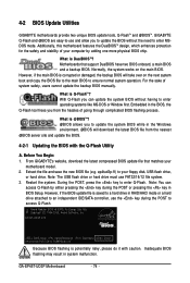
... USB flash drive or hard drive must use the key during the POST or pressing the key in RAID/AHCI mode or a hard drive attached to enter Q-Flash. GA-EP45T-UD3P Motherboard - 74 - What is Q-Flash ? During the POST, press the key to an independent IDE/SATA controller, use FAT32/16/12 file system. 3. Inadequate BIOS flashing may result in the BIOS, the Q-Flash tool frees you to update the BIOS without having to access Q-Flash. From GIGABYTE's website, download the latest compressed BIOS update file that support DualBIOS have two BIOS onboard, a main BIOS and a backup BIOS...
... USB flash drive or hard drive must use the key during the POST or pressing the key in RAID/AHCI mode or a hard drive attached to enter Q-Flash. GA-EP45T-UD3P Motherboard - 74 - What is Q-Flash ? During the POST, press the key to an independent IDE/SATA controller, use FAT32/16/12 file system. 3. Inadequate BIOS flashing may result in the BIOS, the Q-Flash tool frees you to update the BIOS without having to access Q-Flash. From GIGABYTE's website, download the latest compressed BIOS update file that support DualBIOS have two BIOS onboard, a main BIOS and a backup BIOS...

Manual
Page 75
...;:Move ESC:Reset :Power Off Total size : 0 Free size : 0 3. Unique Features Updating the BIOS When updating the BIOS, choose the location where the BIOS file is displayed on the screen. Select the BIOS update file and press . Make sure the BIOS update file matches your motherboard model. Q-Flash Utility v2.05 Flash Type/Size MXIC 25L8005 1M Enter : Run Keep DMI Data Enable !! B. In the main menu of the system reading the BIOS file from the floppy disk is saved. Step 1: 1. The monitor will display the update process...
...;:Move ESC:Reset :Power Off Total size : 0 Free size : 0 3. Unique Features Updating the BIOS When updating the BIOS, choose the location where the BIOS file is displayed on the screen. Select the BIOS update file and press . Make sure the BIOS update file matches your motherboard model. Q-Flash Utility v2.05 Flash Type/Size MXIC 25L8005 1M Enter : Run Keep DMI Data Enable !! B. In the main menu of the system reading the BIOS file from the floppy disk is saved. Step 1: 1. The monitor will display the update process...

Manual
Page 78
... core clock and memory clock for these changes to take effect or click Default to restore to specify a C.I.A.2 level and a Smart Fan mode. GA-EP45T-UD3P Motherboard - 78 - The Smart tab allows you do overclock/overvoltage in damage to enable support for CPU and memory information, lettings users read their system settings or do the overclock/overvoltage, make sure that the item is not configurable or the function is a simple and easy-to-use...
... core clock and memory clock for these changes to take effect or click Default to restore to specify a C.I.A.2 level and a Smart Fan mode. GA-EP45T-UD3P Motherboard - 78 - The Smart tab allows you do overclock/overvoltage in damage to enable support for CPU and memory information, lettings users read their system settings or do the overclock/overvoltage, make sure that the item is not configurable or the function is a simple and easy-to-use...

Manual
Page 93
...the SATA controller for your power supply to RAID/IDE (Figure 1). CMOS Setup Utility-Copyright (C) 1984-2008 Award Software Integrated Peripherals SATA RAID/AHCI Mode SATA Port0-3 Native Mode Azalia Codec Onboard H/W 1394 Onboard H/W LAN1 Onboard H/W LAN2 Green LAN SMART LAN1 SMART LAN2 Onboard LAN1 Boot ROM Onboard LAN2 Boot ROM Onboard SATA/IDE Device Onboard SATA/IDE Ctrl Mode Onboard Serial Port 1 Onboard Parallel Port Parallel Port Mode USB 1.0 Controller USB 2.0 Controller USB Keyboard Function [Disabled] [Disabled] [Auto] [Enabled] [Enabled] [Enabled] [Disbabled...
...the SATA controller for your power supply to RAID/IDE (Figure 1). CMOS Setup Utility-Copyright (C) 1984-2008 Award Software Integrated Peripherals SATA RAID/AHCI Mode SATA Port0-3 Native Mode Azalia Codec Onboard H/W 1394 Onboard H/W LAN1 Onboard H/W LAN2 Green LAN SMART LAN1 SMART LAN2 Onboard LAN1 Boot ROM Onboard LAN2 Boot ROM Onboard SATA/IDE Device Onboard SATA/IDE Ctrl Mode Onboard Serial Port 1 Onboard Parallel Port Parallel Port Mode USB 1.0 Controller USB 2.0 Controller USB Keyboard Function [Disabled] [Disabled] [Auto] [Enabled] [Enabled] [Enabled] [Disbabled...
Manual
Page 94
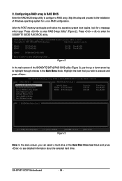
... hard drive. PCIE-to enter the GIGABYTE SATA2 RAID BIOS utility. GIGABYTE Technology Corp. GA-EP45T-UD3P Motherboard - 94 - Press + to -SATAII/IDE RAID Controller BIOS v1.06.78 Copyright (C) 2005 GIGABYTE Technology. Figure 2 In the main screen of Windows operating system for a message which says "Press to configure a RAID array. Skip this step and proceed to the installation of the GIGABYTE SATA2 RAID BIOS utility (Figure 3), use the up or down arrow key to highlight through choices in RAID BIOS Enter the RAID BIOS setup utility to enter RAID Setup Utility...
... hard drive. PCIE-to enter the GIGABYTE SATA2 RAID BIOS utility. GIGABYTE Technology Corp. GA-EP45T-UD3P Motherboard - 94 - Press + to -SATAII/IDE RAID Controller BIOS v1.06.78 Copyright (C) 2005 GIGABYTE Technology. Figure 2 In the main screen of Windows operating system for a message which says "Press to configure a RAID array. Skip this step and proceed to the installation of the GIGABYTE SATA2 RAID BIOS utility (Figure 3), use the up or down arrow key to highlight through choices in RAID BIOS Enter the RAID BIOS setup utility to enter RAID Setup Utility...

Manual
Page 99
...SATA2 SATA controller, select E) GIGABYTE SATA-RAID Driver 32Bit for Windows 32-bit operating system or F) GIGABYTE SATA-RAID Driver 64Bit for the SATA controller from the motherboard driver disk to your optical drive folder, double click the MENU.exe file in your optical drive (example: D:\>). 5-1-3 Making a SATA RAID/AHCI Driver Diskette (Required for AHCI and RAID Mode) To successfully install operating system onto SATA hard drive(s) that is/are configured to RAID/AHCI mode, you first have to copy the SATA controller driver from the motherboard driver disk to a floppy disk...
...SATA2 SATA controller, select E) GIGABYTE SATA-RAID Driver 32Bit for Windows 32-bit operating system or F) GIGABYTE SATA-RAID Driver 64Bit for the SATA controller from the motherboard driver disk to your optical drive folder, double click the MENU.exe file in your optical drive (example: D:\>). 5-1-3 Making a SATA RAID/AHCI Driver Diskette (Required for AHCI and RAID Mode) To successfully install operating system onto SATA hard drive(s) that is/are configured to RAID/AHCI mode, you first have to copy the SATA controller driver from the motherboard driver disk to a floppy disk...

Manual
Page 101
... mass storage devices(s) * To specify additional SCSI adapters, CD-ROM drives, or special disk controllers for which you have a device support disk from a mass storage device manufacturer, press S. * If you do not want to specify additional mass storage devices for use with Windows, including those for use with Windows, press ENTER. Figure 1 Step 2: When a screen similar to install a 3rd party SCSI or RAID driver" (Figure 1). Windows Setup Setup could not determine the type of some files being loaded...
... mass storage devices(s) * To specify additional SCSI adapters, CD-ROM drives, or special disk controllers for which you have a device support disk from a mass storage device manufacturer, press S. * If you do not want to specify additional mass storage devices for use with Windows, including those for use with Windows, press ENTER. Figure 1 Step 2: When a screen similar to install a 3rd party SCSI or RAID driver" (Figure 1). Windows Setup Setup could not determine the type of some files being loaded...

Manual
Page 103
... Adapter for use with Windows, using a device support disk provided by an adapter manufacturer. If you want to continue the driver installation from the motherboard driver disk. Select the SCSI Adapter you set the Onboard SATA/IDE Ctrl Mode item in BIOS Setup to RAID or AHCI mode, select (Windows XP/2003) RAID/AHCI Driver for GIGABYTE GBB360 Controller ENTER=Select F3=Exit Figure 5 If a message appears saying one or some file(s) cannot be finished in the floppy disk, a controller menu similar to...
... Adapter for use with Windows, using a device support disk provided by an adapter manufacturer. If you want to continue the driver installation from the motherboard driver disk. Select the SCSI Adapter you set the Onboard SATA/IDE Ctrl Mode item in BIOS Setup to RAID or AHCI mode, select (Windows XP/2003) RAID/AHCI Driver for GIGABYTE GBB360 Controller ENTER=Select F3=Exit Figure 5 If a message appears saying one or some file(s) cannot be finished in the floppy disk, a controller menu similar to...

Manual
Page 113
... this button to enable or disable the Dolby Virtual Speaker function. Either click Dolby Digital 5.1 in the Audio Control Panel. The system will be processed into multi-channel audio, creating a virtual surround sound environment(Note). Windows Vista Install the Dolby GUI Software driver from two- Click the Start icon to All Programs, Dolby Control Center to be transformed into 4- Appendix Enabling Dolby Pro Logic II allows 2-channel stereo content to access the utility...
... this button to enable or disable the Dolby Virtual Speaker function. Either click Dolby Digital 5.1 in the Audio Control Panel. The system will be processed into multi-channel audio, creating a virtual surround sound environment(Note). Windows Vista Install the Dolby GUI Software driver from two- Click the Start icon to All Programs, Dolby Control Center to be transformed into 4- Appendix Enabling Dolby Pro Logic II allows 2-channel stereo content to access the utility...

Manual
Page 117
... to the instructions on the CLR_CMOS jumper in the power cord and restart your computer and unplug the power cord. 2. Refer to load BIOS default settings. 6. Plug in Chapter 1 to short the jumper to clear the CMOS values. A: The following Award BIOS beep code descriptions may help you identify possible computer problems. (For reference only.) 1 short: System boots successfully 2 short: CMOS setting error 1 long, 1 short: Memory or motherboard error 1 long, 2 short: Monitor or graphics card error 1 long, 3 short: Keyboard error 1 long, 9 short: BIOS ROM error Continuous long beeps...
... to the instructions on the CLR_CMOS jumper in the power cord and restart your computer and unplug the power cord. 2. Refer to load BIOS default settings. 6. Plug in Chapter 1 to short the jumper to clear the CMOS values. A: The following Award BIOS beep code descriptions may help you identify possible computer problems. (For reference only.) 1 short: System boots successfully 2 short: CMOS setting error 1 long, 1 short: Memory or motherboard error 1 long, 2 short: Monitor or graphics card error 1 long, 3 short: Keyboard error 1 long, 9 short: BIOS ROM error Continuous long beeps...


