
Manual
Page 4
Table of Contents Box Contents...6 Optional Items...6 GA-EP45-UD3 Motherboard Layout 7 Block Diagram...8 Chapter 1 Hardware Installation 9 1-1 Installation Precautions 9 1-2 Product Specifications 10 1-3 Installing the CPU and CPU Cooler 13 1-3-1 Installing the CPU 13 1-3-2 Installing the CPU ...
Table of Contents Box Contents...6 Optional Items...6 GA-EP45-UD3 Motherboard Layout 7 Block Diagram...8 Chapter 1 Hardware Installation 9 1-1 Installation Precautions 9 1-2 Product Specifications 10 1-3 Installing the CPU and CPU Cooler 13 1-3-1 Installing the CPU 13 1-3-2 Installing the CPU ...

Manual
Page 6
.... 12CF1-2SERPW-0*R) S/PDIF In cable (Part No. 12CR1-1SPDIN-0*R) COM port cable (Part No. 12CF1-1CM001-3*R) LPT port cable (Part No. 12CF1-1LP001-0*R) - 6 - Box Contents GA-EP45-UD3 motherboard Motherboard driver disk User's Manual Quick Installation Guide One IDE cable Two SATA 3Gb/s cables I/O Shield • The box contents above are subject to change without...
.... 12CF1-2SERPW-0*R) S/PDIF In cable (Part No. 12CR1-1SPDIN-0*R) COM port cable (Part No. 12CF1-1CM001-3*R) LPT port cable (Part No. 12CF1-1LP001-0*R) - 6 - Box Contents GA-EP45-UD3 motherboard Motherboard driver disk User's Manual Quick Installation Guide One IDE cable Two SATA 3Gb/s cables I/O Shield • The box contents above are subject to change without...

Manual
Page 7
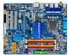
GA-EP45-UD3 Motherboard Layout KB_MS R_SPDIF USB_1394_2 ATX_12V_2X4 USB_1394_1 R_USB PWR_FAN LGA775 CPU_FAN PHASE_LED ATX GA-EP45-UD3 USB_LAN AUDIO F_AUDIO SYS_FAN1 PCIEX1_1 RTL8111C PCIEX1_2 PCIEX16 CODEC PCIEX1_3 BAT SPDIF_O CI PCI1 IT8718 PCI2 SPDIF_I PCI3 CD_IN Intel® P45 IDE SYS_FAN2 Intel® ICH10 GIGABYTE SATA2 SATA2_4 SATA2_2 SATA2_0 TSB43AB23 FDD SATA2_5 SATA2_3 SATA2_1 M_BIOS B_BIOS PWR_LED CLR_CMOS COMA LPT F1_1394 F_USB2 F_USB1 F_PANEL DDR2_1 DDR2_2 DDR2_3 DDR2_4 GSATA2_0 GSATA2_1 - 7 -
GA-EP45-UD3 Motherboard Layout KB_MS R_SPDIF USB_1394_2 ATX_12V_2X4 USB_1394_1 R_USB PWR_FAN LGA775 CPU_FAN PHASE_LED ATX GA-EP45-UD3 USB_LAN AUDIO F_AUDIO SYS_FAN1 PCIEX1_1 RTL8111C PCIEX1_2 PCIEX16 CODEC PCIEX1_3 BAT SPDIF_O CI PCI1 IT8718 PCI2 SPDIF_I PCI3 CD_IN Intel® P45 IDE SYS_FAN2 Intel® ICH10 GIGABYTE SATA2 SATA2_4 SATA2_2 SATA2_0 TSB43AB23 FDD SATA2_5 SATA2_3 SATA2_1 M_BIOS B_BIOS PWR_LED CLR_CMOS COMA LPT F1_1394 F_USB2 F_USB1 F_PANEL DDR2_1 DDR2_2 DDR2_3 DDR2_4 GSATA2_0 GSATA2_1 - 7 -

Manual
Page 10
...PCI Express x1 slots w 3 x PCI slots Storage Interface w South Bridge: - 6 x SATA 3Gb/s connectors (SATA2_0, SATA2_1, SATA2_2, SATA2_3, SATA2_4, SATA2_5) supporting up to 6 SATA 3Gb/s devices w GIGABYTE SATA2 chip: - 1 x IDE connector supporting ATA-133/100/66/33 and up to 2 IDE devices - 2 x SATA 3Gb/s connectors (GSATA2_0, GSATA2_1) supporting up to 1 floppy disk...TSB43AB23 chip w Up to 3 IEEE 1394a ports (2 on the back panel, 4 via the IEEE 1394a bracket connected to the internal IEEE 1394a header) GA-EP45-UD3 Motherboard - 10 -
...PCI Express x1 slots w 3 x PCI slots Storage Interface w South Bridge: - 6 x SATA 3Gb/s connectors (SATA2_0, SATA2_1, SATA2_2, SATA2_3, SATA2_4, SATA2_5) supporting up to 6 SATA 3Gb/s devices w GIGABYTE SATA2 chip: - 1 x IDE connector supporting ATA-133/100/66/33 and up to 2 IDE devices - 2 x SATA 3Gb/s connectors (GSATA2_0, GSATA2_1) supporting up to 1 floppy disk...TSB43AB23 chip w Up to 3 IEEE 1394a ports (2 on the back panel, 4 via the IEEE 1394a bracket connected to the internal IEEE 1394a header) GA-EP45-UD3 Motherboard - 10 -
Manual
Page 12
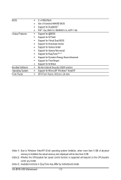
GA-EP45-UD3 Motherboard - 12 - BIOS Unique Features Bundled Software Operating System Form Factor w 2 x 8 Mbit flash w Use of licensed AWARD BIOS w Support for DualBIOS™ w PnP 1.0a, DMI 2.0, SM ... CPU/system fan speed control function is supported will depend on the CPU/system cooler you install. (Note 3) Available functions in EasyTune may differ by motherboard model.
GA-EP45-UD3 Motherboard - 12 - BIOS Unique Features Bundled Software Operating System Form Factor w 2 x 8 Mbit flash w Use of licensed AWARD BIOS w Support for DualBIOS™ w PnP 1.0a, DMI 2.0, SM ... CPU/system fan speed control function is supported will depend on the CPU/system cooler you install. (Note 3) Available functions in EasyTune may differ by motherboard model.

Manual
Page 14
...the protective socket cover when the CPU is properly inserted, replace the load plate and push the CPU socket lever back into its locked position. GA-EP45-UD3 Motherboard - 14 - Step 5: Once the CPU is not installed.) Step 4: Hold the CPU with the socket alignment keys) and gently insert the CPU... into the motherboard CPU socket. B. Step 2: Lift the metal load plate from the CPU socket. (DO NOT touch socket contacts.) Step 3: Remove the protective socket cover...
...the protective socket cover when the CPU is properly inserted, replace the load plate and push the CPU socket lever back into its locked position. GA-EP45-UD3 Motherboard - 14 - Step 5: Once the CPU is not installed.) Step 4: Hold the CPU with the socket alignment keys) and gently insert the CPU... into the motherboard CPU socket. B. Step 2: Lift the metal load plate from the CPU socket. (DO NOT touch socket contacts.) Step 3: Remove the protective socket cover...

Manual
Page 16
... during the POST. When memory modules of the same capacity, brand, speed, and chips be used . (Go to GIGABYTE's website for optimum performance. GA-EP45-UD3 Motherboard - 16 - If you begin to install the memory: • Make sure that memory of the memory. DS/SS...Read the following guidelines before you are unable to insert the memory, switch the direction. 1-4-1 Dual Channel Memory Configuration This motherboard provides four DDR2 memory sockets and supports Dual Channel Technology. Enabling Dual Channel memory mode will automatically detect the specifications and capacity...
... during the POST. When memory modules of the same capacity, brand, speed, and chips be used . (Go to GIGABYTE's website for optimum performance. GA-EP45-UD3 Motherboard - 16 - If you begin to install the memory: • Make sure that memory of the memory. DS/SS...Read the following guidelines before you are unable to insert the memory, switch the direction. 1-4-1 Dual Channel Memory Configuration This motherboard provides four DDR2 memory sockets and supports Dual Channel Technology. Enabling Dual Channel memory mode will automatically detect the specifications and capacity...

Manual
Page 18
... installing all expansion cards, replace the chassis cover(s). 6. If necessary, go to BIOS Setup to install an expansion card: • Make sure the motherboard supports the expansion card. Example: Installing and Removing a PCI Express Graphics Card: • Installing a Graphics Card: Gently push down on the card ...not rock. • Removing the Card: Gently push back on the lever on the card are completely inserted into the PCI Express slot. GA-EP45-UD3 Motherboard - 18 - Make sure the metal contacts on the slot and then lift the card straight out from the slot. Secure the card's...
... installing all expansion cards, replace the chassis cover(s). 6. If necessary, go to BIOS Setup to install an expansion card: • Make sure the motherboard supports the expansion card. Example: Installing and Removing a PCI Express Graphics Card: • Installing a Graphics Card: Gently push down on the card ...not rock. • Removing the Card: Gently push back on the lever on the card are completely inserted into the PCI Express slot. GA-EP45-UD3 Motherboard - 18 - Make sure the metal contacts on the slot and then lift the card straight out from the slot. Secure the card's...

Manual
Page 20
Microphones must be used to connect front speakers in a 4/5.1/7.1-channel audio configuration. GA-EP45-UD3 Motherboard - 20 - Line Out Jack (Green) The default line out jack. figuration in jack. Use this audio jack for line in devices such as an optical ...
Microphones must be used to connect front speakers in a 4/5.1/7.1-channel audio configuration. GA-EP45-UD3 Motherboard - 20 - Line Out Jack (Green) The default line out jack. figuration in jack. Use this audio jack for line in devices such as an optical ...

Manual
Page 22
.../Off) GND GND GND -5V +5V +5V +5V (Only for 2x12-pin ATX) GND (Only for 2x4-pin 12V) 7 +12V 8 +12V 12 24 1 13 ATX GA-EP45-UD3 Motherboard ATX: Pin No. 1 2 3 4 5 6 7 8 9 10 11 12 Definition Pin No. 3.3V 13 3.3V 14 GND 15 +5V 16 GND 17 +5V 18 GND 19 Power Good... mainly supplies power to the power connector in the correct orientation. If the 12V power connector is turned off and all the components on the motherboard. Before connecting the power connector, first make sure the power supply is not connected, the computer will not start. • Use of the power connector...
.../Off) GND GND GND -5V +5V +5V +5V (Only for 2x12-pin ATX) GND (Only for 2x4-pin 12V) 7 +12V 8 +12V 12 24 1 13 ATX GA-EP45-UD3 Motherboard ATX: Pin No. 1 2 3 4 5 6 7 8 9 10 11 12 Definition Pin No. 3.3V 13 3.3V 14 GND 15 +5V 16 GND 17 +5V 18 GND 19 Power Good... mainly supplies power to the power connector in the correct orientation. If the 12V power connector is turned off and all the components on the motherboard. Before connecting the power connector, first make sure the power supply is not connected, the computer will not start. • Use of the power connector...

Manual
Page 24
... 3Gb/s standard and are compatible with SATA 1.5Gb/s standard. SATA2_4 7 7 SATA2_5 SATA2_2 SATA2_3 Pin No. Definition SATA2_0 1 GND 1 2 TXP 3 TXN 1 4 GND SATA2_1 5 RXN 6 RXP 7 GND GA-EP45-UD3 Motherboard - 24 - Please connect the L-shaped end of the IDE devices (for example, master or slave). (For information about configuring master/slave settings for the IDE...
... 3Gb/s standard and are compatible with SATA 1.5Gb/s standard. SATA2_4 7 7 SATA2_5 SATA2_2 SATA2_3 Pin No. Definition SATA2_0 1 GND 1 2 TXP 3 TXN 1 4 GND SATA2_1 5 RXN 6 RXP 7 GND GA-EP45-UD3 Motherboard - 24 - Please connect the L-shaped end of the IDE devices (for example, master or slave). (For information about configuring master/slave settings for the IDE...

Manual
Page 26
... panel design may configure the way to turn off (S5). • PW (Power Switch, Red): Connects to the power switch on the chassis front panel. GA-EP45-UD3 Motherboard - 26 - Note the positive and negative pins before connecting the cables. You may differ by issuing a beep code. Refer to Chapter 5, "Troubleshooting," for more information...
... panel design may configure the way to turn off (S5). • PW (Power Switch, Red): Connects to the power switch on the chassis front panel. GA-EP45-UD3 Motherboard - 26 - Note the positive and negative pins before connecting the cables. You may differ by issuing a beep code. Refer to Chapter 5, "Troubleshooting," for more information...

Manual
Page 28
...the same time. For information about connecting the S/PDIF digital audio cable, carefully read the manual for digital audio output from your motherboard to your graphics card if you wish to connect an HDMI display to the graphics card and have digital audio output from your...some graphics cards may require you to use a S/PDIF digital audio cable for your motherboard to an audio device that supports digital audio out via an optional S/PDIF In cable. Pin No. Definition 1 SPDIFO 1 2 GND GA-EP45-UD3 Motherboard - 28 - For purchasing the optional S/PDIF In cable, please contact the local ...
...the same time. For information about connecting the S/PDIF digital audio cable, carefully read the manual for digital audio output from your motherboard to your graphics card if you wish to connect an HDMI display to the graphics card and have digital audio output from your...some graphics cards may require you to use a S/PDIF digital audio cable for your motherboard to an audio device that supports digital audio out via an optional S/PDIF In cable. Pin No. Definition 1 SPDIFO 1 2 GND GA-EP45-UD3 Motherboard - 28 - For purchasing the optional S/PDIF In cable, please contact the local ...

Manual
Page 30
... one parallel port via an optional COM port cable. Pin No. Definition 1 NDCD- 9 1 10 2 2 NSIN 3 NSOUT 4 NDTR- 5 GND 6 NDSR- 7 NRTS- 8 NCTS- 9 NRI- 10 No Pin GA-EP45-UD3 Motherboard - 30 - For purchasing the optional LPT port cable, please contact the local dealer. 25 1 26 2 Pin No. 1 2 3 4 5 6 7 8 9 10 11 12 13 Definition STBAFDPD0 ERRPD1 INITPD2...
... one parallel port via an optional COM port cable. Pin No. Definition 1 NDCD- 9 1 10 2 2 NSIN 3 NSOUT 4 NDTR- 5 GND 6 NDSR- 7 NRTS- 8 NCTS- 9 NRI- 10 No Pin GA-EP45-UD3 Motherboard - 30 - For purchasing the optional LPT port cable, please contact the local dealer. 25 1 26 2 Pin No. 1 2 3 4 5 6 7 8 9 10 11 12 13 Definition STBAFDPD0 ERRPD1 INITPD2...

Manual
Page 32
... the place of the battery holder, making them short for 5 seconds.) 3. To enable the Phase LED display function, please first enable Dynamic Energy Saver Advanced. GA-EP45-UD3 Motherboard - 32 - Replace the battery when the battery voltage drops to touch the positive and negative terminals of purchase or local dealer if you are not...
... the place of the battery holder, making them short for 5 seconds.) 3. To enable the Phase LED display function, please first enable Dynamic Energy Saver Advanced. GA-EP45-UD3 Motherboard - 32 - Replace the battery when the battery voltage drops to touch the positive and negative terminals of purchase or local dealer if you are not...

Manual
Page 34
...49. : BIOS SETUP\Q-FLASH Press the key to enter BIOS Setup or to access the Q-Flash utility directly without entering BIOS Setup. GA-EP45-UD3 Motherboard - 34 - To show the BIOS POST screen. The POST Screen Award Modular BIOS v6.00PG, An Energy Star Ally Copyright (C) ... first boot device without having to Xpress Recovery2 during the POST. 2-1 Startup Screen The following screens may appear when the computer boots. Motherboard Model BIOS Version EP45-UD3 F7a . . . . : BIOS Setup : XpressRecovery2 : Boot Menu : Qflash 04/02/2009-P45-ICH10-7A69PG01C-00 Function Keys Function...
...49. : BIOS SETUP\Q-FLASH Press the key to enter BIOS Setup or to access the Q-Flash utility directly without entering BIOS Setup. GA-EP45-UD3 Motherboard - 34 - To show the BIOS POST screen. The POST Screen Award Modular BIOS v6.00PG, An Energy Star Ally Copyright (C) ... first boot device without having to Xpress Recovery2 during the POST. 2-1 Startup Screen The following screens may appear when the computer boots. Motherboard Model BIOS Version EP45-UD3 F7a . . . . : BIOS Setup : XpressRecovery2 : Boot Menu : Qflash 04/02/2009-P45-ICH10-7A69PG01C-00 Function Keys Function...

Manual
Page 36
... view the BIOS settings but not to make changes in effect. First enter the profile name (to erase the default profile name, use this task.) GA-EP45-UD3 Motherboard - 36 - It allows you to restrict access to the system and BIOS Setup. Pressing to the confirmation message will exit BIOS Setup. (Pressing can use...
... view the BIOS settings but not to make changes in effect. First enter the profile name (to erase the default profile name, use this task.) GA-EP45-UD3 Motherboard - 36 - It allows you to restrict access to the system and BIOS Setup. Pressing to the confirmation message will exit BIOS Setup. (Pressing can use...

Manual
Page 38
... to allow the CPU Host Frequency item below to automatically set the R.G.B. Fine CPU Clock Ratio (Note) Allows you install a CPU that supports this feature. GA-EP45-UD3 Motherboard - 38 -
... to allow the CPU Host Frequency item below to automatically set the R.G.B. Fine CPU Clock Ratio (Note) Allows you install a CPU that supports this feature. GA-EP45-UD3 Motherboard - 38 -

Manual
Page 40
... is the memory frequency that supports this function. (G)MCH Frequency Latch Allows you to set the CPU clock prior to enhance memory performance when enabled. GA-EP45-UD3 Motherboard - 40 -
... is the memory frequency that supports this function. (G)MCH Frequency Latch Allows you to set the CPU clock prior to enhance memory performance when enabled. GA-EP45-UD3 Motherboard - 40 -

Manual
Page 42
Twr2rd(Different Rank) Options are : Auto (default), +800ps~-700ps. ESC: Exit F1: General Help F7: Optimized Defaults GA-EP45-UD3 Motherboard - 42 - DIMM1 Clock Skew Control Options are : Auto (default), 1~15. Trd2rd(Different Rank) Options are : Auto (default), 0-Normal, 1-Advanced. tRD Phase2 Adjustment Options are : Auto (...
Twr2rd(Different Rank) Options are : Auto (default), +800ps~-700ps. ESC: Exit F1: General Help F7: Optimized Defaults GA-EP45-UD3 Motherboard - 42 - DIMM1 Clock Skew Control Options are : Auto (default), 1~15. Trd2rd(Different Rank) Options are : Auto (default), 0-Normal, 1-Advanced. tRD Phase2 Adjustment Options are : Auto (...


