Manual
Page 3
...translated, transmitted, or published in the use of GIGABYTE. For product-related information, check on our website at: http://www.gigabyte.com Identifying Your Motherboard Revision The revision number on your motherboard revision before updating motherboard BIOS, drivers, or when looking for technical information.... and features in this : "REV: X.X." The trademarks mentioned in this product, GIGABYTE provides the following types of documentations: For quick set-up of the motherboard is the property of this manual may be made by copyright laws and is 1.0....
...translated, transmitted, or published in the use of GIGABYTE. For product-related information, check on our website at: http://www.gigabyte.com Identifying Your Motherboard Revision The revision number on your motherboard revision before updating motherboard BIOS, drivers, or when looking for technical information.... and features in this : "REV: X.X." The trademarks mentioned in this product, GIGABYTE provides the following types of documentations: For quick set-up of the motherboard is the property of this manual may be made by copyright laws and is 1.0....
Manual
Page 4
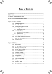
Table of Contents Box Contents...6 Optional Items...6 GA-990FXA-UD5 Motherboard Layout 7 GA-990FXA-UD5 Motherboard Block Diagram 8 Chapter 1 Hardware Installation 9 1-1 Installation Precautions 9 1-2 Product Specifications 10 1-3 Installing the CPU and CPU Cooler 13 1-3-1 Installing the CPU 13 1-3-2 Installing the CPU Cooler ...
Table of Contents Box Contents...6 Optional Items...6 GA-990FXA-UD5 Motherboard Layout 7 GA-990FXA-UD5 Motherboard Block Diagram 8 Chapter 1 Hardware Installation 9 1-1 Installation Precautions 9 1-2 Product Specifications 10 1-3 Installing the CPU and CPU Cooler 13 1-3-1 Installing the CPU 13 1-3-2 Installing the CPU Cooler ...
Manual
Page 6
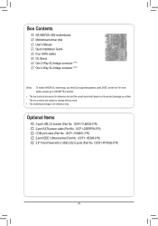
... more details, please go to GIGABYTE's website. • The box contents above are subject to change without notice. • The motherboard image is for reference only and the actual items shall depend on the product package you need SLI-supported graphics cards, BIOS, and driver. Box Contents GA-990FXA-UD5 motherboard Motherboard driver disk User's Manual Quick...
... more details, please go to GIGABYTE's website. • The box contents above are subject to change without notice. • The motherboard image is for reference only and the actual items shall depend on the product package you need SLI-supported graphics cards, BIOS, and driver. Box Contents GA-990FXA-UD5 motherboard Motherboard driver disk User's Manual Quick...
Manual
Page 7
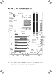
GA-990FXA-UD5 Motherboard Layout KB_MS_USB OPTICAL ATX_12V USB_1394_ESATA USB_ESATA Marvell 88SE9172 CPU_FAN Socket AM3+ PWR_FAN R_USB30 USB_LAN AUDIO Etron EJ168 Realtek RTL8111E PCIEX1(Note) PCIEX16_1 PCIEX4_1 AMD 990FX GA-990FXA-UD5 CODEC PCIEX16_2 PCIEX4_2 VIA VT6308 PCIEX8 PCI F_AUDIO F_1394 COMA ATX BAT DDR3_4 DDR3_2 DDR3_3 DDR3_1 Marvell 88SE9172 AMD SB950 B_BIOS M_BIOS GSATA3_7 GSATA3_6 SATA3_4 ...
GA-990FXA-UD5 Motherboard Layout KB_MS_USB OPTICAL ATX_12V USB_1394_ESATA USB_ESATA Marvell 88SE9172 CPU_FAN Socket AM3+ PWR_FAN R_USB30 USB_LAN AUDIO Etron EJ168 Realtek RTL8111E PCIEX1(Note) PCIEX16_1 PCIEX4_1 AMD 990FX GA-990FXA-UD5 CODEC PCIEX16_2 PCIEX4_2 VIA VT6308 PCIEX8 PCI F_AUDIO F_1394 COMA ATX BAT DDR3_4 DDR3_2 DDR3_3 DDR3_1 Marvell 88SE9172 AMD SB950 B_BIOS M_BIOS GSATA3_7 GSATA3_6 SATA3_4 ...
Manual
Page 8
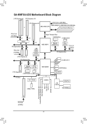
GA-990FXA-UD5 Motherboard Block Diagram 2 PCI Express x8 1 PCI Express x16 1 PCI Express x16 CPU CLK+/- (200 MHz) or DDR3 2000(O.C.)/1866/1600/1333/1066 MHz AM3+/AM3 ...
GA-990FXA-UD5 Motherboard Block Diagram 2 PCI Express x8 1 PCI Express x16 1 PCI Express x16 CPU CLK+/- (200 MHz) or DDR3 2000(O.C.)/1866/1600/1333/1066 MHz AM3+/AM3 ...

Manual
Page 9
...that all cables and power connectors of your hardware components are connected. • To prevent damage to the motherboard, do not remove or break motherboard S/N (Serial Number) sticker or warranty sticker provided by unplugging the power cord from the power outlet before ... connectors on the computer power during the installation process can become damaged as a motherboard, CPU or memory. Hardware Installation Chapter 1 Hardware Installation 1-1 Installation Precautions The motherboard contains numerous delicate electronic circuits and components which can lead to damage to system ...
...that all cables and power connectors of your hardware components are connected. • To prevent damage to the motherboard, do not remove or break motherboard S/N (Serial Number) sticker or warranty sticker provided by unplugging the power cord from the power outlet before ... connectors on the computer power during the installation process can become damaged as a motherboard, CPU or memory. Hardware Installation Chapter 1 Hardware Installation 1-1 Installation Precautions The motherboard contains numerous delicate electronic circuits and components which can lead to damage to system ...
Manual
Page 12
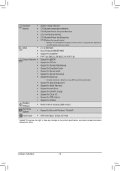
... Center ŠŠ Support for Xpress Install ŠŠ Support for Xpress Recovery2 ŠŠ Support for EasyTune * Available functions in EasyTune may differ by motherboard model. ŠŠ Support for Easy Energy Saver ŠŠ Support for Smart Recovery ŠŠ Support for Auto Green ŠŠ Support for ON...
... Center ŠŠ Support for Xpress Install ŠŠ Support for Xpress Recovery2 ŠŠ Support for EasyTune * Available functions in EasyTune may differ by motherboard model. ŠŠ Support for Easy Energy Saver ŠŠ Support for Smart Recovery ŠŠ Support for Auto Green ŠŠ Support for ON...
Manual
Page 13
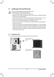
... meet the standard requirements for the latest CPU support list.) • Always turn on the computer if the CPU cooler is not recommended that the motherboard supports the CPU. (Go to GIGABYTE's website for the peripherals.
... meet the standard requirements for the latest CPU support list.) • Always turn on the computer if the CPU cooler is not recommended that the motherboard supports the CPU. (Go to GIGABYTE's website for the peripherals.

Manual
Page 14
... on the CPU socket and gently insert the CPU into the fully locked position. B. Follow the steps below to correctly install the CPU into the motherboard CPU socket. • Before installing the CPU, make sure to turn off the computer and unplug the power cord from the power outlet to prevent...
... on the CPU socket and gently insert the CPU into the fully locked position. B. Follow the steps below to correctly install the CPU into the motherboard CPU socket. • Before installing the CPU, make sure to turn off the computer and unplug the power cord from the power outlet to prevent...

Manual
Page 15
Inadequately removing the CPU cooler may adhere to the mounting lug on the motherboard. 1-3-2 Installing the CPU Cooler Follow the steps below to correctly install the CPU cooler on the CPU. (The following procedure uses the GIGABYTE cooler as the picture above shows) to lock into place. (Refer to your CPU cooler installation...
Inadequately removing the CPU cooler may adhere to the mounting lug on the motherboard. 1-3-2 Installing the CPU Cooler Follow the steps below to correctly install the CPU cooler on the CPU. (The following procedure uses the GIGABYTE cooler as the picture above shows) to lock into place. (Refer to your CPU cooler installation...
Manual
Page 16
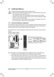
... only one direction. DS/SS DDR3_3 - If you begin to insert the memory, switch the direction. 1-4-1 Dual Channel Memory Configuration This motherboard provides four DDR3 memory sockets and supports Dual Channel Technology. Hardware Installation - 16 - When enabling Dual Channel mode with two memory modules,... of the memory. It is recommended that you install them in Dual Channel mode. 1. A memory module can be used . (Go to GIGABYTE's website for optimum performance. DS/SS DS/SS DDR3_2 DS/SS - After the memory is installed. 2. 1-4 Installing the Memory Read the following...
... only one direction. DS/SS DDR3_3 - If you begin to insert the memory, switch the direction. 1-4-1 Dual Channel Memory Configuration This motherboard provides four DDR3 memory sockets and supports Dual Channel Technology. Hardware Installation - 16 - When enabling Dual Channel mode with two memory modules,... of the memory. It is recommended that you install them in Dual Channel mode. 1. A memory module can be used . (Go to GIGABYTE's website for optimum performance. DS/SS DS/SS DDR3_2 DS/SS - After the memory is installed. 2. 1-4 Installing the Memory Read the following...

Manual
Page 17
... clips at both ends of the memory, push down on the left, place your memory modules in one direction. Place the memory module on this motherboard. As indicated in the picture on the memory and insert it can only fit in the memory sockets. Step 1: Note the orientation of the socket...
... clips at both ends of the memory, push down on the left, place your memory modules in one direction. Place the memory module on this motherboard. As indicated in the picture on the memory and insert it can only fit in the memory sockets. Step 1: Note the orientation of the socket...
Manual
Page 18
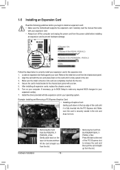
... in the slot. 3. 1-5 Installing an Expansion Card Read the following guidelines before installing an expansion card to install an expansion card: • Make sure the motherboard supports the expansion card.
... in the slot. 3. 1-5 Installing an Expansion Card Read the following guidelines before installing an expansion card to install an expansion card: • Make sure the motherboard supports the expansion card.
Manual
Page 19
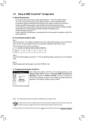
... be needed or not depending on the number of your graphics cards. The 3-Way CrossFireX technology currently support Windows 7 and Vista operating systems - A CrossFireX-supported motherboard with your graphics cards for more information about enabling CrossFireX technology. - 19 - Recommended 2/3-Way CrossFireX Configurations: PCIEX16_1 PCIEX16_2 PCIEX8 PCIEX4_1 PCIEX4_2 2-Way a a - - - - - - 3-Way a a a - - - - Hardware Installation...
... be needed or not depending on the number of your graphics cards. The 3-Way CrossFireX technology currently support Windows 7 and Vista operating systems - A CrossFireX-supported motherboard with your graphics cards for more information about enabling CrossFireX technology. - 19 - Recommended 2/3-Way CrossFireX Configurations: PCIEX16_1 PCIEX16_2 PCIEX8 PCIEX4_1 PCIEX4_2 2-Way a a - - - - - - 3-Way a a a - - - - Hardware Installation...

Manual
Page 21
... rear speakers in a 5.1/7.1-channel audio configuration. Refer to prevent an electrical short inside the cable connector. - 21 - Do not rock it straight out from the motherboard. •• When removing the cable, pull it side to side to the instructions on setting up a 2/4/5.1/7.1-channel audio configuration in devices such as an...
... rear speakers in a 5.1/7.1-channel audio configuration. Refer to prevent an electrical short inside the cable connector. - 21 - Do not rock it straight out from the motherboard. •• When removing the cable, pull it side to side to the instructions on setting up a 2/4/5.1/7.1-channel audio configuration in devices such as an...

Manual
Page 22
... devices and your devices are compliant with the connectors you wish to connect. • Before installing the devices, be sure to the connector on the motherboard. 1-8 Internal Connectors 1 3 5 2 6 8 7 4 11 10 17 14 4 15 12 13 16 9 1) ATX_12V 2) ATX 3) CPU_FAN 4) SYS_FAN1/2 5) PWR_FAN 6) BAT 7) SATA3_0/1/2/3/4/5 8) GSATA3_6/7 9) F_PANEL 10) F_AUDIO 11) SPDIF_O 12) F_USB1...
... devices and your devices are compliant with the connectors you wish to connect. • Before installing the devices, be sure to the connector on the motherboard. 1-8 Internal Connectors 1 3 5 2 6 8 7 4 11 10 17 14 4 15 12 13 16 9 1) ATX_12V 2) ATX 3) CPU_FAN 4) SYS_FAN1/2 5) PWR_FAN 6) BAT 7) SATA3_0/1/2/3/4/5 8) GSATA3_6/7 9) F_PANEL 10) F_AUDIO 11) SPDIF_O 12) F_USB1...

Manual
Page 23
... supply can lead to the power connector in the correct orientation. If the 12V power connector is turned off and all the components on the motherboard. Connect the power supply cable to an unstable or unbootable system. 8 4 5 1 ATX_12V ATX_12V: Pin No. 1 2 3 4 5 6 7 8 Definition GND (Only for 2x4-pin 12V) GND (Only for...
... supply can lead to the power connector in the correct orientation. If the 12V power connector is turned off and all the components on the motherboard. Connect the power supply cable to an unstable or unbootable system. 8 4 5 1 ATX_12V ATX_12V: Pin No. 1 2 3 4 5 6 7 8 Definition GND (Only for 2x4-pin 12V) GND (Only for...
Manual
Page 24
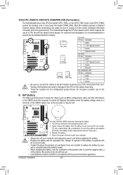
... negative side (-) of the battery (the positive side should face up). •• Used batteries must be lost. The motherboard supports CPU fan speed control, which requires the use a metal object like a screwdriver to replace the battery by removing the battery...unplug the power cord before replacing the battery. •• Replace the battery with fan speed control design. 3/4/5) CPU_FAN/SYS_FAN1/SYS_FAN2/PWR_FAN (Fan Headers) The motherboard has a 4-pin CPU fan header (CPU_FAN), a 4-pin (SYS_FAN1) and a 3-pin (SYS_FAN2) system fan headers, and a 3-pin power fan header ...
... negative side (-) of the battery (the positive side should face up). •• Used batteries must be lost. The motherboard supports CPU fan speed control, which requires the use a metal object like a screwdriver to replace the battery by removing the battery...unplug the power cord before replacing the battery. •• Replace the battery with fan speed control design. 3/4/5) CPU_FAN/SYS_FAN1/SYS_FAN2/PWR_FAN (Fan Headers) The motherboard has a 4-pin CPU fan header (CPU_FAN), a 4-pin (SYS_FAN1) and a 3-pin (SYS_FAN2) system fan headers, and a 3-pin power fan header ...

Manual
Page 27
...8226; Audio signals will make the device unable to Chapter 5, "Configuring 2/4/5.1/7.1-Channel Audio." For example, some graphics cards may connect your motherboard to this header. Hardware Installation Definition Pin No. If your expansion card. FPWorMiSnwfoitrcmh (aXt5i8oAn-OaCb)out connecting the front panel audio module that...simultane- For information about connecting the S/PDIF digital audio cable, carefully read the manual for digital audio output from your motherboard to your graphics card if you want to mute the back panel audio (only supported when using an HD front panel...
...8226; Audio signals will make the device unable to Chapter 5, "Configuring 2/4/5.1/7.1-Channel Audio." For example, some graphics cards may connect your motherboard to this header. Hardware Installation Definition Pin No. If your expansion card. FPWorMiSnwfoitrcmh (aXt5i8oAn-OaCb)out connecting the front panel audio module that...simultane- For information about connecting the S/PDIF digital audio cable, carefully read the manual for digital audio output from your motherboard to your graphics card if you want to mute the back panel audio (only supported when using an HD front panel...
Manual
Page 30
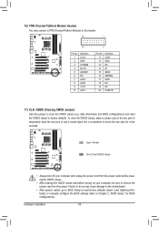
... to this jumper to Chapter 2, "BIOS Setup," for a few seconds. Hardware Installation - 30 - 1 16) TPM (Trusted Platform Module Header) You may cause damage to the motherboard. •• After system restart, go to BIOS Setup to load factory defaults (select Load Optimized Defaults) or manually configure the BIOS settings (refer to...
... to this jumper to Chapter 2, "BIOS Setup," for a few seconds. Hardware Installation - 30 - 1 16) TPM (Trusted Platform Module Header) You may cause damage to the motherboard. •• After system restart, go to BIOS Setup to load factory defaults (select Load Optimized Defaults) or manually configure the BIOS settings (refer to...


