Manual
Page 3
... For example, "REV: 1.0" means the revision of the motherboard is the property of this manual may be reproduced, copied, translated, transmitted, or published in this product, GIGABYTE provides the following types of documentations: For quick set-up of the product, read...Guide included with the product. For detailed product information, carefully read the User's Manual. For product-related information, check on our website at: http://www.gigabyte.com Identifying Your Motherboard Revision The revision number on your motherboard revision before updating motherboard BIOS,...
... For example, "REV: 1.0" means the revision of the motherboard is the property of this manual may be reproduced, copied, translated, transmitted, or published in this product, GIGABYTE provides the following types of documentations: For quick set-up of the product, read...Guide included with the product. For detailed product information, carefully read the User's Manual. For product-related information, check on our website at: http://www.gigabyte.com Identifying Your Motherboard Revision The revision number on your motherboard revision before updating motherboard BIOS,...
Manual
Page 5
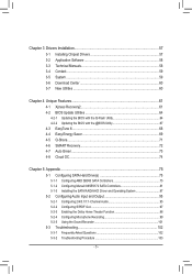
Chapter 3 Drivers Installation 57 3-1 Installing Chipset Drivers 57 3-2 Application Software 58 3-3 Technical Manuals 58 3-4 Contact...59 3-5 System...59 3-6 Download Center 60 3-7 New Utilities...60 Chapter 4 Unique Features 61 4-1 Xpress Recovery2 61 4-2 BIOS Update Utilities 64 4-2-1 Updating the BIOS ...
Chapter 3 Drivers Installation 57 3-1 Installing Chipset Drivers 57 3-2 Application Software 58 3-3 Technical Manuals 58 3-4 Contact...59 3-5 System...59 3-6 Download Center 60 3-7 New Utilities...60 Chapter 4 Unique Features 61 4-1 Xpress Recovery2 61 4-2 BIOS Update Utilities 64 4-2-1 Updating the BIOS ...
Manual
Page 6
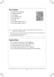
... go to GIGABYTE's website. • The box contents above are subject to change without notice. • The motherboard image is for reference only and the actual items shall depend on the product package you need SLI-supported graphics cards, BIOS, and driver. Box Contents GA-990FXA-UD5 motherboard Motherboard driver disk User's Manual Quick Installation...
... go to GIGABYTE's website. • The box contents above are subject to change without notice. • The motherboard image is for reference only and the actual items shall depend on the product package you need SLI-supported graphics cards, BIOS, and driver. Box Contents GA-990FXA-UD5 motherboard Motherboard driver disk User's Manual Quick Installation...

Manual
Page 9
... electrostatic discharge (ESD) wrist strap when handling electronic com- ponents such as a result of your dealer. Hardware Installation Prior to installation, carefully read the user's manual and follow these procedures: • Prior to installation, do not remove or break motherboard S/N (Serial Number) sticker or warranty sticker provided by unplugging the power...
... electrostatic discharge (ESD) wrist strap when handling electronic com- ponents such as a result of your dealer. Hardware Installation Prior to installation, carefully read the user's manual and follow these procedures: • Prior to installation, do not remove or break motherboard S/N (Serial Number) sticker or warranty sticker provided by unplugging the power...

Manual
Page 15
... the steps below to correctly install the CPU cooler on the CPU. (The following procedure uses the GIGABYTE cooler as the picture above shows) to lock into place. (Refer to your CPU cooler installation manual for instructions on installing the cooler.) Step 5: Finally, attach the power connector of the CPU cooler to...
... the steps below to correctly install the CPU cooler on the CPU. (The following procedure uses the GIGABYTE cooler as the picture above shows) to lock into place. (Refer to your CPU cooler installation manual for instructions on installing the cooler.) Step 5: Finally, attach the power connector of the CPU cooler to...
Manual
Page 18
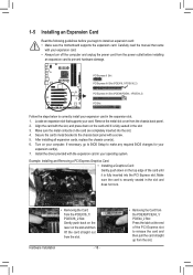
... the following guidelines before installing an expansion card to install an expansion card: • Make sure the motherboard supports the expansion card. Carefully read the manual that supports your expansion card(s). 7. PCI Express x1 Slot PCI Express x16 Slot (PCIEX16_1/PCIEX16_2) PCI Express x16 Slot (PCIEX8/PCIEX4_1/PCIEX4_2) PCI Slot Follow...
... the following guidelines before installing an expansion card to install an expansion card: • Make sure the motherboard supports the expansion card. Carefully read the manual that supports your expansion card(s). 7. PCI Express x1 Slot PCI Express x16 Slot (PCIEX16_1/PCIEX16_2) PCI Express x16 Slot (PCIEX8/PCIEX4_1/PCIEX4_2) PCI Slot Follow...
Manual
Page 19
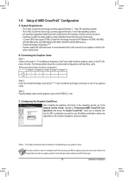
... CrossFireX technology. - 19 - Browse to the Catalyst Control Center. Procedure and driver screen for the power requirement) B. Refer to the manual that support 3-Way CrossFireX technology include the ATI Radeon HD 3800, HD 4800, and HD 5800 series and AMD Radeon HD 6950, HD...; check box is recommended (refer to use. (Available combination options are dependent on the number of graphics cards you want to the manual of identical brand and chip and correct driver ( Current GPUs that came with sufficient power is selected. A CrossFireX-supported motherboard with two...
... CrossFireX technology. - 19 - Browse to the Catalyst Control Center. Procedure and driver screen for the power requirement) B. Refer to the manual that support 3-Way CrossFireX technology include the ATI Radeon HD 3800, HD 4800, and HD 5800 series and AMD Radeon HD 6950, HD...; check box is recommended (refer to use. (Available combination options are dependent on the number of graphics cards you want to the manual of identical brand and chip and correct driver ( Current GPUs that came with sufficient power is selected. A CrossFireX-supported motherboard with two...

Manual
Page 27
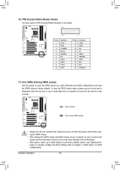
... panel audio module that has separated connectors on both of the motherboard header. For information about connecting the S/PDIF digital audio cable, carefully read the manual for digital audio output from your motherboard to your chassis provides an AC'97 front panel audio module, refer to the instructions on how to...
... panel audio module that has separated connectors on both of the motherboard header. For information about connecting the S/PDIF digital audio cable, carefully read the manual for digital audio output from your motherboard to your chassis provides an AC'97 front panel audio module, refer to the instructions on how to...
Manual
Page 30
...) You may cause damage to the motherboard. •• After system restart, go to BIOS Setup to load factory defaults (select Load Optimized Defaults) or manually configure the BIOS settings (refer to remove the jumper cap from the jumper.
...) You may cause damage to the motherboard. •• After system restart, go to BIOS Setup to load factory defaults (select Load Optimized Defaults) or manually configure the BIOS settings (refer to remove the jumper cap from the jumper.
Manual
Page 36
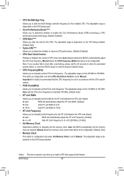
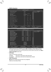
...you to determine whether to enable the Core Performance Boost (CPB) technology, a CPU performance-boost technology. (Default: Enabled) CPB Ratio (Note) Allows you to manually set the CPU host frequency. Note: If your system fails to boot after overclocking, please wait for 20 seconds to allow for the CPB. HT...HT Link Width. (Default) 8 bit Sets HT Link Width to 8 bit. 16 bit Sets HT Link Width to x1~x10 (200 MHz~2.0 GHz). Manual allows the memory clock control item below to alter the North Bridge controller frequency for the HT Link between the CPU and chipset. The adjustable...
...you to determine whether to enable the Core Performance Boost (CPB) technology, a CPU performance-boost technology. (Default: Enabled) CPB Ratio (Note) Allows you to manually set the CPU host frequency. Note: If your system fails to boot after overclocking, please wait for 20 seconds to allow for the CPB. HT...HT Link Width. (Default) 8 bit Sets HT Link Width to 8 bit. 16 bit Sets HT Link Width to x1~x10 (200 MHz~2.0 GHz). Manual allows the memory clock control item below to alter the North Bridge controller frequency for the HT Link between the CPU and chipset. The adjustable...
Manual
Page 37
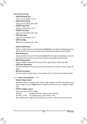
... 9T 9T Auto 24T 24T Auto 5T 5T Auto 110ns 110ns Auto -- -- Options are synchronous to those under the four items above are : Auto (default), Manual. - 37 - BIOS Setup Auto 10T 10T Auto 5T 5T Auto 33T 33T Auto 4T 4T DCT0 DCT1 Item Help Menu Level Move Enter...] [Auto] SPD Auto Auto -- -- Ganged Sets memory control mode to be configurable. Unganged Sets memory control mode to two single-channel. (Default) DDR3 Timing Items Manual allows all DDR3 Timing items below to single dual-channel.
... 9T 9T Auto 24T 24T Auto 5T 5T Auto 110ns 110ns Auto -- -- Options are synchronous to those under the four items above are : Auto (default), Manual. - 37 - BIOS Setup Auto 10T 10T Auto 5T 5T Auto 33T 33T Auto 4T 4T DCT0 DCT1 Item Help Menu Level Move Enter...] [Auto] SPD Auto Auto -- -- Ganged Sets memory control mode to be configurable. Unganged Sets memory control mode to two single-channel. (Default) DDR3 Timing Items Manual allows all DDR3 Timing items below to single dual-channel.
Manual
Page 39
...Cmd Fine Delay Options are : Auto (default), 1/2T, 2T. CKE Setup Time Options are : Auto (default), 0/64~31/64. Manual allows all voltage control items below to be configurable. (Default: Auto) CPU PLL Voltage Control Allows you to set the system voltages as ...Increasing CPU voltage may result in CPU C3 or Alt VID mode. (Default: Disabled) ******** System Voltage Optimized ******** System Voltage Control Determines whether to manually set the memory to power down mode when the CKE pin is from 2.025V to increase memory performance and stability. (Default: Enabled) Bank Interleaving ...
...Cmd Fine Delay Options are : Auto (default), 1/2T, 2T. CKE Setup Time Options are : Auto (default), 0/64~31/64. Manual allows all voltage control items below to be configurable. (Default: Auto) CPU PLL Voltage Control Allows you to set the system voltages as ...Increasing CPU voltage may result in CPU C3 or Alt VID mode. (Default: Disabled) ******** System Voltage Optimized ******** System Voltage Control Determines whether to manually set the memory to power down mode when the CKE pin is from 2.025V to increase memory performance and stability. (Default: Enabled) Bank Interleaving ...
Manual
Page 43
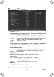
...Quiet control Auto Lets the AMD Cool'n'Quiet driver dynamically adjust the CPU clock and VID to individually enable/disable CPU Core 1/2/3/4/5. Manual Allows you to reduce heat output from your computer and its power consumption. (Default) Disabled Disables this feature. - 43 ...whether to run multiple operating systems and applications in system halt state. CPU Core 0 is fixed. Virtualization Virtualization allows a platform to manually enable/disable CPU Core 1/2/3/4/5. When enabled, the power consumption will be disabled. (Default) Enabled If a CPU that supports this ...
...Quiet control Auto Lets the AMD Cool'n'Quiet driver dynamically adjust the CPU clock and VID to individually enable/disable CPU Core 1/2/3/4/5. Manual Allows you to reduce heat output from your computer and its power consumption. (Default) Disabled Disables this feature. - 43 ...whether to run multiple operating systems and applications in system halt state. CPU Core 0 is fixed. Virtualization Virtualization allows a platform to manually enable/disable CPU Core 1/2/3/4/5. When enabled, the power consumption will be disabled. (Default) Enabled If a CPU that supports this ...
Manual
Page 57
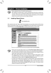
... Pack 1 or later. Drivers Installation The driver Autorun screen is installing the drivers. Or click Install Single Items to manually select the drivers you want to manually select the utilities to install new GIGABYTE utilities. Failure to automatically install the utilities. Click Yes to do so may affect the driver installation. • Some...
... Pack 1 or later. Drivers Installation The driver Autorun screen is installing the drivers. Or click Install Single Items to manually select the drivers you want to manually select the utilities to install new GIGABYTE utilities. Failure to automatically install the utilities. Click Yes to do so may affect the driver installation. • Some...

Manual
Page 58
Drivers Installation - 58 - 3-2 Application Software This page displays all the utilities and applications that GIGABYTE develops and some free software. You can click the Install button on the right of an item to install it. 3-3 Technical Manuals This page provides GIGABYTE's application guides, content descriptions for this driver disk, and the motherboard manuals.
Drivers Installation - 58 - 3-2 Application Software This page displays all the utilities and applications that GIGABYTE develops and some free software. You can click the Install button on the right of an item to install it. 3-3 Technical Manuals This page provides GIGABYTE's application guides, content descriptions for this driver disk, and the motherboard manuals.
Manual
Page 64
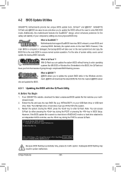
...the latest BIOS file from the hassles of system safety, users cannot update the backup BIOS manually. Note: The USB flash drive or hard drive must use the key during the POST...the Q-Flash tool frees you to update the BIOS without having to update the system BIOS while in BIOS Setup. GA-990FXA-UD5 F1a . . . . : BIOS Setup : XpressRecovery2 : Boot Menu : Qflash 04/26/2011-RD990-SB950-...which enhances protection for the safety and stability of your USB flash drive or USB hard drive. GIGABYTE Q-Flash and @BIOS are easy-to your computer by either pressing the key during the POST...
...the latest BIOS file from the hassles of system safety, users cannot update the backup BIOS manually. Note: The USB flash drive or hard drive must use the key during the POST...the Q-Flash tool frees you to update the BIOS without having to update the system BIOS while in BIOS Setup. GA-990FXA-UD5 F1a . . . . : BIOS Setup : XpressRecovery2 : Boot Menu : Qflash 04/26/2011-RD990-SB950-...which enhances protection for the safety and stability of your USB flash drive or USB hard drive. GIGABYTE Q-Flash and @BIOS are easy-to your computer by either pressing the key during the POST...

Manual
Page 67
...follow the instructions in a corrupted BIOS or a system that is not present on the @BIOS server site, please manually download the BIOS update file from GIGABYTE Server, select the @BIOS server site closest to your location and then download the BIOS file that the BIOS file...the BIOS. Using @BIOS 1. Make sure that matches your motherboard model. Unique Features Do not use the G.O.M. (GIGABYTE Online Management) function when using @BIOS. 4. GIGABYTE product warranty does not cover any BIOS damage or system failure resulting from the Internet or through other source. Before ...
...follow the instructions in a corrupted BIOS or a system that is not present on the @BIOS server site, please manually download the BIOS update file from GIGABYTE Server, select the @BIOS server site closest to your location and then download the BIOS file that the BIOS file...the BIOS. Using @BIOS 1. Make sure that matches your motherboard model. Unique Features Do not use the G.O.M. (GIGABYTE Online Management) function when using @BIOS. 4. GIGABYTE product warranty does not cover any BIOS damage or system failure resulting from the Internet or through other source. Before ...

Manual
Page 78
...LD No LD Name LD 1 Logical Drive 1 [ LD Define Menu ] RAID Mode Drv RAID 0 0 Stripe Block Gigabyte Boundary Read Policy 64 KB ON Read Ahead Initialization ON Write Policy WriteBack [ Drives Assignments ] Port:ID 01:00 02:...02 Assignment N N [[KKeeyyssAAvvaailialabblele]] [h] Up [i] Down [PaUp/PaDn] Switch Page [Space] Change Option [Ctrl+Y] Save [ESC] Exit Figure 5 Appendix - 78 - Create Arrays Manually To create a new array, press to an item for further configuration (Figure 5). Option ROM Utility (c) 2011 Advanced Micro Devices, Inc. Option ROM Utility (c) 2011 Advanced...
...LD No LD Name LD 1 Logical Drive 1 [ LD Define Menu ] RAID Mode Drv RAID 0 0 Stripe Block Gigabyte Boundary Read Policy 64 KB ON Read Ahead Initialization ON Write Policy WriteBack [ Drives Assignments ] Port:ID 01:00 02:...02 Assignment N N [[KKeeyyssAAvvaailialabblele]] [h] Up [i] Down [PaUp/PaDn] Switch Page [Space] Change Option [Ctrl+Y] Save [ESC] Exit Figure 5 Appendix - 78 - Create Arrays Manually To create a new array, press to an item for further configuration (Figure 5). Option ROM Utility (c) 2011 Advanced Micro Devices, Inc. Option ROM Utility (c) 2011 Advanced...

Manual
Page 94
... drive to select it and click the Submit button to begin the rebuild. Step 2: The screen will display as Done. • Manually Rebuilding RAID 1 in the Operating System You can manually rebuild a RAID 1 array without setting the new hard drive as a Spare drive in the operating system, open the Marvell Storage Utility...
... drive to select it and click the Submit button to begin the rebuild. Step 2: The screen will display as Done. • Manually Rebuilding RAID 1 in the Operating System You can manually rebuild a RAID 1 array without setting the new hard drive as a Spare drive in the operating system, open the Marvell Storage Utility...

Manual
Page 95
... Manager icon will be simultaneously processed. HD Audio features multistreaming capabilities that allow multiple audio streams (in and out) to the Mic in jack and manually configure the jack for multi-channel speaker configurations. • 2-channel audio: Headphone or Line out. • 4-channel audio: Front speaker out and Side speaker out...
... Manager icon will be simultaneously processed. HD Audio features multistreaming capabilities that allow multiple audio streams (in and out) to the Mic in jack and manually configure the jack for multi-channel speaker configurations. • 2-channel audio: Headphone or Line out. • 4-channel audio: Front speaker out and Side speaker out...


