Manual
Page 1
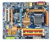
GA-965P-DQ6 Intel® CoreTM 2 Extreme quad-core / CoreTM 2 Quad / Intel® CoreTM 2 Extreme dual-core / CoreTM 2 Duo / Intel® Pentium® Processor Extreme Edition / Intel® Pentium® D / Pentium® 4 LGA775 Processor Motherboard User's Manual Rev. 3301 12ME-965PDQ6-3301R * The WEEE marking on the product indicates this product must not be disposed of with user's other household waste and must be handed over to a designated collection point for the recycling of waste electrical and electronic equipment!! * The WEEE marking applies only in European Union's member states.
GA-965P-DQ6 Intel® CoreTM 2 Extreme quad-core / CoreTM 2 Quad / Intel® CoreTM 2 Extreme dual-core / CoreTM 2 Duo / Intel® Pentium® Processor Extreme Edition / Intel® Pentium® D / Pentium® 4 LGA775 Processor Motherboard User's Manual Rev. 3301 12ME-965PDQ6-3301R * The WEEE marking on the product indicates this product must not be disposed of with user's other household waste and must be handed over to a designated collection point for the recycling of waste electrical and electronic equipment!! * The WEEE marking applies only in European Union's member states.
Manual
Page 3
...written content provided with this product, Gigabyte has categorized the user manual in any form or by any means without prior notice. For more product details, please click onto Gigabyte's website at www.gigabyte.com.tw Product Manual Classification In order to their respective companies.... Copyright © 2007 GIGA-BYTE TECHNOLOGY CO., LTD. No part of Gigabyte. Specifications and features are legally registered to...
...written content provided with this product, Gigabyte has categorized the user manual in any form or by any means without prior notice. For more product details, please click onto Gigabyte's website at www.gigabyte.com.tw Product Manual Classification In order to their respective companies.... Copyright © 2007 GIGA-BYTE TECHNOLOGY CO., LTD. No part of Gigabyte. Specifications and features are legally registered to...
Manual
Page 9
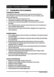
...that all cables and power connectors are no leftover screws or metal components placed on top of Non-Warranty 1. Prior to be an unofficial Gigabyte product. - 9 - Damage due to installation, please follow the instructions below: 1. Damage due to use exceeding the permitted parameters. ... unplug its components. 5. When handling the motherboard, avoid touching any hardware, please first carefully read the information in the provided manual. 3. Installation Notices 1. Before using the product, please verify that the power supply is best to wear an electrostatic discharge (...
...that all cables and power connectors are no leftover screws or metal components placed on top of Non-Warranty 1. Prior to be an unofficial Gigabyte product. - 9 - Damage due to installation, please follow the instructions below: 1. Damage due to use exceeding the permitted parameters. ... unplug its components. 5. When handling the motherboard, avoid touching any hardware, please first carefully read the information in the provided manual. 3. Installation Notices 1. Before using the product, please verify that the power supply is best to wear an electrostatic discharge (...
Manual
Page 14
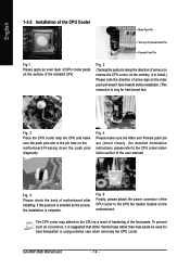
..., please refer to the CPU cooler installation section of the user manual) Fig. 5 Please check the back of the heat paste. To prevent such an occurrence, it is to the pin hole on the motherboard.Pressing down the push pins diagonally. GA-965P-DQ6 Motherboard - 14 - Fig. 4 Please make sure the push pins aim...
..., please refer to the CPU cooler installation section of the user manual) Fig. 5 Please check the back of the heat paste. To prevent such an occurrence, it is to the pin hole on the motherboard.Pressing down the push pins diagonally. GA-965P-DQ6 Motherboard - 14 - Fig. 4 Please make sure the push pins aim...

Manual
Page 17
... power cable from the power supply to your computer's chassis cover, screws and slot bracket from its power source and read the expansion card's installation manual before installing the expansion card in system BIOS Setup. 8. Install related driver in the motherboard. 4. The motherboard includes a PCIE_12V power connector, which provides extra power...
... power cable from the power supply to your computer's chassis cover, screws and slot bracket from its power source and read the expansion card's installation manual before installing the expansion card in system BIOS Setup. 8. Install related driver in the motherboard. 4. The motherboard includes a PCIE_12V power connector, which provides extra power...
Manual
Page 34
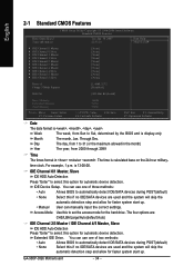
...F6: Fail-Safe Defaults ESC: Exit F1: General Help F7: Optimized Defaults Date The date format is 13:00:00. Through Dec. Extended IDE Drive. GA-965P-DQ6 Motherboard - 34 - IDE Channel 0/1 Master, Slave IDE HDD Auto-Detection Press "Enter" to set the access mode for automatic device detection. You can ...if no IDE/SATA devices are used and the system will skip the automatic detection step and allow for faster system start up . • Manual User can use one of two methods: • Auto Allows BIOS to Sat, determined by the BIOS and is calculated base on the 24...
...F6: Fail-Safe Defaults ESC: Exit F1: General Help F7: Optimized Defaults Date The date format is 13:00:00. Through Dec. Extended IDE Drive. GA-965P-DQ6 Motherboard - 34 - IDE Channel 0/1 Master, Slave IDE HDD Auto-Detection Press "Enter" to set the access mode for automatic device detection. You can ...if no IDE/SATA devices are used and the system will skip the automatic detection step and allow for faster system start up . • Manual User can use one of two methods: • Auto Allows BIOS to Sat, determined by the BIOS and is calculated base on the 24...
Manual
Page 45
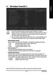
... Control PCI-E OverVoltage Control (G)MCH OverVoltage Control FSB OverVoltage Control CPU Voltage Control Normal CPU Vcore [Auto] [9X] [Disabled] 333 [Auto] [Disabled] [Auto] 800 [Option 1] [Manual] [Normal] [Normal] [Normal] [Normal] [Normal] 1.25000V Item Help Menu Level : Move Enter: Select F5: Previous Values +/-/PU/PD: Value F10: Save F6: Fail-Safe Defaults...
... Control PCI-E OverVoltage Control (G)MCH OverVoltage Control FSB OverVoltage Control CPU Voltage Control Normal CPU Vcore [Auto] [9X] [Disabled] 333 [Auto] [Disabled] [Auto] 800 [Option 1] [Manual] [Normal] [Normal] [Normal] [Normal] [Normal] 1.25000V Item Help Menu Level : Move Enter: Select F5: Previous Values +/-/PU/PD: Value F10: Save F6: Fail-Safe Defaults...

Manual
Page 46
... 150Mhz Set PCI Express frequency from 100 MHz to 700 MHz. If you wish to adjust the item manually, set CPU Host Frequency to 133 MHz. If you wish to adjust the item manually, set CPU Host Frequency to 266 MHz. Sports Set C.I .A.2 to Racing. Racing Set C.I .A.2 ... is the memory frequency automatically adjusted according to the CPU Host Frequency(Mhz) and System Memory Multiplier settings. (Note 2) Applies only when the GA-965P-DQ6 motherboard (rev. 3.3) is the normal frequency of the memory being installed. If you use a 1066 MHz FSB processor, please set "System Voltage...
... 150Mhz Set PCI Express frequency from 100 MHz to 700 MHz. If you wish to adjust the item manually, set CPU Host Frequency to 133 MHz. If you wish to adjust the item manually, set CPU Host Frequency to 266 MHz. Sports Set C.I .A.2 to Racing. Racing Set C.I .A.2 ... is the memory frequency automatically adjusted according to the CPU Host Frequency(Mhz) and System Memory Multiplier settings. (Note 2) Applies only when the GA-965P-DQ6 motherboard (rev. 3.3) is the normal frequency of the memory being installed. If you use a 1066 MHz FSB processor, please set "System Voltage...
Manual
Page 47
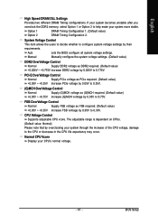
... allows the users to decide whether to configure system voltage settings by overclocking your system through the increase of the CPU voltage, damage to 0.75V. Manual Manually configure the system voltage settings. (Default value) DDR2 OverVoltage Control Normal Supply DDR2 voltage as FSB required. (Default value) +0.05V ~ +0.35V Increase FSB voltrage by...
... allows the users to decide whether to configure system voltage settings by overclocking your system through the increase of the CPU voltage, damage to 0.75V. Manual Manually configure the system voltage settings. (Default value) DDR2 OverVoltage Control Normal Supply DDR2 voltage as FSB required. (Default value) +0.05V ~ +0.35V Increase FSB voltrage by...
Manual
Page 65
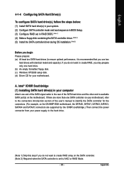
...power connector from your power supply to the hard drive. (Note 1) Skip this step if you do not want to create RAID array on the GA-965P-DQ6 motherboard, the SATAII0, SATAII1, SATAII2, SATAII3, SATAII4 and SATAII5 connectors are more than one hard drive. (b) An empty formatted floppy disk. (c) ...174; ICH8R Southbridge (1) Installing SATA hard drive(s) in your computer Attach one end of the SATA signal cable to the rear of the user's manual to identify the SATA controller for the connectors. (For example, on the SATA controller. (Note 2) Required when the SATA controller is recommended ...
...power connector from your power supply to the hard drive. (Note 1) Skip this step if you do not want to create RAID array on the GA-965P-DQ6 motherboard, the SATAII0, SATAII1, SATAII2, SATAII3, SATAII4 and SATAII5 connectors are more than one hard drive. (b) An empty formatted floppy disk. (c) ...174; ICH8R Southbridge (1) Installing SATA hard drive(s) in your computer Attach one end of the SATA signal cable to the rear of the user's manual to identify the SATA controller for the connectors. (For example, on the SATA controller. (Note 2) Required when the SATA controller is recommended ...

Manual
Page 73
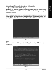
..., including those for which you have a device support disk from a mass storage device manufacturer, press S. * If you see the "Press F6 if you need to manually specify an adapter. English (5) Installing SATA controller driver during OS installation (Required for AHCI and RAID Mode) Now that below appears, insert the floppy disk...
..., including those for which you have a device support disk from a mass storage device manufacturer, press S. * If you see the "Press F6 if you need to manually specify an adapter. English (5) Installing SATA controller driver during OS installation (Required for AHCI and RAID Mode) Now that below appears, insert the floppy disk...
Manual
Page 76
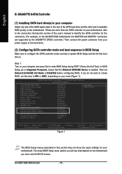
If there are supported by the GIGABYTE SATA2 controller.) Then connect the power connector from your computer and press Del to available SATA port(s) on the motherboard you have and the BIOS ... see shall depend on the motherboard. GIGABYTE SATA2 Controller (1) Installing SATA hard drive(s) in this item to IDE or AHCI, depending on the GA-965P-DQ6 motherboard, the GSATAII0 and GSATAII1 connectors are more than one end of the SATA signal cable to the rear of the user's manual to identify the SATA controller for...
If there are supported by the GIGABYTE SATA2 controller.) Then connect the power connector from your computer and press Del to available SATA port(s) on the motherboard you have and the BIOS ... see shall depend on the motherboard. GIGABYTE SATA2 Controller (1) Installing SATA hard drive(s) in this item to IDE or AHCI, depending on the GA-965P-DQ6 motherboard, the GSATAII0 and GSATAII1 connectors are more than one end of the SATA signal cable to the rear of the user's manual to identify the SATA controller for...
Manual
Page 85
... a third party SCSI or RAID driver. Appendix S=Specify Additional Device ENTER=Continue F3=Exit Figure 19 - 85 - Windows Setup Press F6 if you need to manually specify an adapter.
... a third party SCSI or RAID driver. Appendix S=Specify Additional Device ENTER=Continue F3=Exit Figure 19 - 85 - Windows Setup Press F6 if you need to manually specify an adapter.
Manual
Page 96
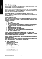
...5 seconds). 4. What do these options. Answer: Some advanced options are hidden in the manual. If your board has a Clear CMOS jumper, please refer to see some boards, a...error 1 long 9 short: BIOS ROM error Continuous long beeps: DRAM error Continuous short beeps: Power error GA-965P-DQ6 Motherboard - 96 - Answer: In some options that 's why the light is still on power. 6....the light of my keyboard/optical mouse still on after system boots up the speaker to GIGABYTE's website. Disconnect the power cord from computer after computer shuts down and that were included...
...5 seconds). 4. What do these options. Answer: Some advanced options are hidden in the manual. If your board has a Clear CMOS jumper, please refer to see some boards, a...error 1 long 9 short: BIOS ROM error Continuous long beeps: DRAM error Continuous short beeps: Power error GA-965P-DQ6 Motherboard - 96 - Answer: In some options that 's why the light is still on power. 6....the light of my keyboard/optical mouse still on after system boots up the speaker to GIGABYTE's website. Disconnect the power cord from computer after computer shuts down and that were included...


