Manual
Page 1
GA-965P-DQ6 Intel® CoreTM 2 Extreme quad-core / CoreTM 2 Quad / Intel® CoreTM 2 Extreme dual-core / CoreTM 2 Duo / Intel® Pentium® Processor Extreme Edition / Intel® Pentium® D / Pentium® 4 LGA775 Processor Motherboard User's Manual Rev. 3301 12ME-965PDQ6-3301R * The WEEE marking on the product indicates this product must not be disposed of with user's other household waste and must be handed over to a designated collection point for the recycling of waste electrical and electronic equipment!! * The WEEE marking applies only in European Union's member states.
GA-965P-DQ6 Intel® CoreTM 2 Extreme quad-core / CoreTM 2 Quad / Intel® CoreTM 2 Extreme dual-core / CoreTM 2 Duo / Intel® Pentium® Processor Extreme Edition / Intel® Pentium® D / Pentium® 4 LGA775 Processor Motherboard User's Manual Rev. 3301 12ME-965PDQ6-3301R * The WEEE marking on the product indicates this product must not be disposed of with user's other household waste and must be handed over to a designated collection point for the recycling of waste electrical and electronic equipment!! * The WEEE marking applies only in European Union's member states.
Manual
Page 2
Motherboard GA-965P-DQ6 Nov. 20, 2006 Motherboard GA-965P-DQ6 Nov. 20, 2006
Motherboard GA-965P-DQ6 Nov. 20, 2006 Motherboard GA-965P-DQ6 Nov. 20, 2006
Manual
Page 4
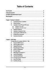
Table of Contents ItemChecklist ...6 OptionalAccessories ...6 GA-965P-DQ6 Motherboard Layout 7 Block Diagram ...8 Chapter 1 Hardware Installation 9 1-1 Considerations Prior to Installation 9 1-2 Feature Summary 10 1-3 Installation of the CPU and CPU Cooler 13 1-3-1 Installation of the CPU ...
Table of Contents ItemChecklist ...6 OptionalAccessories ...6 GA-965P-DQ6 Motherboard Layout 7 Block Diagram ...8 Chapter 1 Hardware Installation 9 1-1 Considerations Prior to Installation 9 1-2 Feature Summary 10 1-3 Installation of the CPU and CPU Cooler 13 1-3-1 Installation of the CPU ...

Manual
Page 7
GA-965P-DQ6 Motherboard Layout KB_MS COAXIAL OPTICAL ATX_12V_2X LGA775 PWR_FAN PCIE_12V ATX COM LPT 1394 USB GA-965P-DQ6 LAN USB AUDIO BATTERY CPU_FAN CLR_CMOS Intel® P965 F_AUDIO PCIE_1 FDD Marvell 8056 PCIE_16_1 DDRII1 DDRII2 DDRII3 DDRII4 PCIE_2 CODEC PCIE_3 CD_IN PCIE_16_2 PCI1 IT8718 PCI2 TPM SPDIF_IN BP_BIOS MAIN_BIOS SATAII0 CI SYS_FAN Intel® ICH8R TSB43AB23 SATAII4 SATAII1 SATAII2 SATAII5 SATAII3 GIGABYTE SATA2 IDE GSATAII1 GSATAII0 F_USB1 F_USB2 F_USB3 F1_1394 F2_1394 PWR_LED F_PANEL - 7 -
GA-965P-DQ6 Motherboard Layout KB_MS COAXIAL OPTICAL ATX_12V_2X LGA775 PWR_FAN PCIE_12V ATX COM LPT 1394 USB GA-965P-DQ6 LAN USB AUDIO BATTERY CPU_FAN CLR_CMOS Intel® P965 F_AUDIO PCIE_1 FDD Marvell 8056 PCIE_16_1 DDRII1 DDRII2 DDRII3 DDRII4 PCIE_2 CODEC PCIE_3 CD_IN PCIE_16_2 PCI1 IT8718 PCI2 TPM SPDIF_IN BP_BIOS MAIN_BIOS SATAII0 CI SYS_FAN Intel® ICH8R TSB43AB23 SATAII4 SATAII1 SATAII2 SATAII5 SATAII3 GIGABYTE SATA2 IDE GSATAII1 GSATAII0 F_USB1 F_USB2 F_USB3 F1_1394 F2_1394 PWR_LED F_PANEL - 7 -
Manual
Page 8
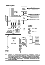
...667 MHz or 833 MHz, depending on the memory being installed. (Note 2) To use a DDRII 800/667 memory module on the motherboard, you must install a 1333/1066/ 800 MHz FSB processor. - 8 - In such a configuration, the actual operating memory frequency will...Switch LAN RJ45 Marvell 8056 x1 PCI Express Bus 2 SATA 3Gb/s ATA-33/66/100/ 133 IDE Channel PCI Bus GIGABYTE SATA2 LGA775 Processor CPU CLK+/(333(Note 1)/266/200/133 MHz) Host Interface DDRII 800/667/533 MHz DIMM(Note 2)... In SPDIF Out 2 PCI PCI CLK (33 MHz) (Note 1) Applies only when the GA-965P-DQ6 motherboard (rev. 3.3) is installed.
...667 MHz or 833 MHz, depending on the memory being installed. (Note 2) To use a DDRII 800/667 memory module on the motherboard, you must install a 1333/1066/ 800 MHz FSB processor. - 8 - In such a configuration, the actual operating memory frequency will...Switch LAN RJ45 Marvell 8056 x1 PCI Express Bus 2 SATA 3Gb/s ATA-33/66/100/ 133 IDE Channel PCI Bus GIGABYTE SATA2 LGA775 Processor CPU CLK+/(333(Note 1)/266/200/133 MHz) Host Interface DDRII 800/667/533 MHz DIMM(Note 2)... In SPDIF Out 2 PCI PCI CLK (33 MHz) (Note 1) Applies only when the GA-965P-DQ6 motherboard (rev. 3.3) is installed.
Manual
Page 9
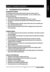
... information in the provided manual. 3. Prior to improper installation. 4. To prevent damage to the motherboard, please do not place the computer system on the motherboard or within a electrostatic shielding container. 5. Turning on the motherboard. Damage due to be an unofficial Gigabyte product. - 9 - Product determined to use of Non-Warranty 1. Hardware Installation Before using the...
... information in the provided manual. 3. Prior to improper installation. 4. To prevent damage to the motherboard, please do not place the computer system on the motherboard or within a electrostatic shielding container. 5. Turning on the motherboard. Damage due to be an unofficial Gigabyte product. - 9 - Product determined to use of Non-Warranty 1. Hardware Installation Before using the...
Manual
Page 10
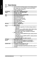
Supports RAID 0, RAID 1, RAID 5, and RAID 10 for Serial ATA Š GIGABYTE SATA2 Controller - 1 IDE connectors with the PCIE_16_2 slot) (Note 3) Š 2 PCI slots GA-965P-DQ6 Motherboard - 10 - Supports RAID 0, RAID 1 and JBOD for Intel® CoreTM 2 Extreme quad-core / CoreTM 2 Extreme dual-core / CoreTM 2 Quad / CoreTM 2 Duo / Pentium® processor Extreme ...
Supports RAID 0, RAID 1, RAID 5, and RAID 10 for Serial ATA Š GIGABYTE SATA2 Controller - 1 IDE connectors with the PCIE_16_2 slot) (Note 3) Š 2 PCI slots GA-965P-DQ6 Motherboard - 10 - Supports RAID 0, RAID 1 and JBOD for Intel® CoreTM 2 Extreme quad-core / CoreTM 2 Extreme dual-core / CoreTM 2 Quad / CoreTM 2 Duo / Pentium® processor Extreme ...
Manual
Page 12
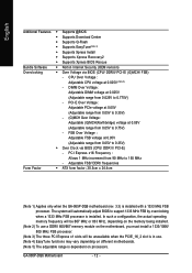
...Adjustable FSB/ DDRII frequencies Form Factor Š ATX form factor; 30.5cm x 24.4cm (Note 1) Applies only when the GA-965P-DQ6 motherboard (rev. 3.3) is dependent on processors. In such a configuration, the actual operating memory frequency will be 667 MHz or 833 ...(Note 3) The three PCI Express x1 slots will automatically adjust BIOS to support 1333 MHz FSB by overclocking when a 1333 MHz FSB processor is installed. GA-965P-DQ6 Motherboard - 12 - DIMM Over Voltage : Adjustable DIMM voltage at 0.05V (Adjustable range from 0.025V to 0.75V) - PCI-E Over Voltage : Adjustable PCIe...
...Adjustable FSB/ DDRII frequencies Form Factor Š ATX form factor; 30.5cm x 24.4cm (Note 1) Applies only when the GA-965P-DQ6 motherboard (rev. 3.3) is dependent on processors. In such a configuration, the actual operating memory frequency will be 667 MHz or 833 ...(Note 3) The three PCI Express x1 slots will automatically adjust BIOS to support 1333 MHz FSB by overclocking when a 1333 MHz FSB processor is installed. GA-965P-DQ6 Motherboard - 12 - DIMM Over Voltage : Adjustable DIMM voltage at 0.05V (Adjustable range from 0.025V to 0.75V) - PCI-E Over Voltage : Adjustable PCIe...
Manual
Page 13
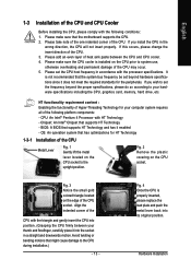
... forefinger, carefully place it enabled - Please set the CPU host frequency in accordance with HT Technology - Hardware Installation Chipset: An Intel® Chipset that the motherboard supports the CPU. 2. Fig. 3 Notice the small gold colored triangle located on the CPU socket. Fig. 4 Once the CPU is properly inserted, please replace the...
... forefinger, carefully place it enabled - Please set the CPU host frequency in accordance with HT Technology - Hardware Installation Chipset: An Intel® Chipset that the motherboard supports the CPU. 2. Fig. 3 Notice the small gold colored triangle located on the CPU socket. Fig. 4 Once the CPU is properly inserted, please replace the...
Manual
Page 14
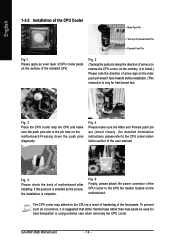
... (This instruction is complete. The CPU cooler may adhere to install.) Please note the direction of arrow sign on the motherboard.Pressing down the push pins diagonally. GA-965P-DQ6 Motherboard - 14 - English 1-3-2 Installation of the CPU Cooler Male Push Pin The top of Female Push Pin Female Push Pin... Fig.1 Please apply an even layer of CPU cooler paste on the motherboard. Fig. 2 (Turning the push pin along the ...
... (This instruction is complete. The CPU cooler may adhere to install.) Please note the direction of arrow sign on the motherboard.Pressing down the push pins diagonally. GA-965P-DQ6 Motherboard - 14 - English 1-3-2 Installation of the CPU Cooler Male Push Pin The top of Female Push Pin Female Push Pin... Fig.1 Please apply an even layer of CPU cooler paste on the motherboard. Fig. 2 (Turning the push pin along the ...
Manual
Page 15
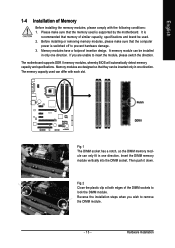
... down. If you wish to insert the module, please switch the direction. It is recommended that they can be used. 2. The motherboard supports DDR II memory modules, whereby BIOS will automatically detect memory capacity and specifications. English 1-4 Installation of Memory Before installing the memory... prevent hardware damage. 3. Before installing or removing memory modules, please make sure that the computer power is supported by the motherboard. A memory module can be inserted only in one direction. Please make sure that the memory used can only fit in one...
... down. If you wish to insert the module, please switch the direction. It is recommended that they can be used. 2. The motherboard supports DDR II memory modules, whereby BIOS will automatically detect memory capacity and specifications. English 1-4 Installation of Memory Before installing the memory... prevent hardware damage. 3. Before installing or removing memory modules, please make sure that the computer power is supported by the motherboard. A memory module can be inserted only in one direction. Please make sure that the memory used can only fit in one...
Manual
Page 16
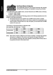
...is recommended to use memory modules of the same color. DS/SS DDRII2 - English Dual Channel Memory Configuration The GA-965P-DQ6 supports the Dual Channel Technology. Intel® Flex Memory Technology offers easier upgrades by allowing different memory sizes to ...Channel Memory configuration table: (DS: Double Side, SS: Single Side, "--": Empty) 2 memory modules 4 memory modules DDRII1 DS/SS - GA-965P-DQ6 Motherboard - 16 - The GA-965P-DQ6 includes 4 DIMM sockets, and each Channel has two DIMM sockets as following: Channel 0 : DDRII1, DDRII2 Channel 1 : DDRII3, DDRII4 ...
...is recommended to use memory modules of the same color. DS/SS DDRII2 - English Dual Channel Memory Configuration The GA-965P-DQ6 supports the Dual Channel Technology. Intel® Flex Memory Technology offers easier upgrades by allowing different memory sizes to ...Channel Memory configuration table: (DS: Double Side, SS: Single Side, "--": Empty) 2 memory modules 4 memory modules DDRII1 DS/SS - GA-965P-DQ6 Motherboard - 16 - The GA-965P-DQ6 includes 4 DIMM sockets, and each Channel has two DIMM sockets as following: Channel 0 : DDRII1, DDRII2 Channel 1 : DDRII3, DDRII4 ...

Manual
Page 17
... can press the latch as the picture to the left shows to your computer's chassis cover. 7. Install related driver in the motherboard. 4. Hardware Installation Ground yourself to prevent damage to release the card. Replace your computer resulting from Electrostatic discharge (ESD). 3.... cable from its power source and read the expansion card's installation manual before installing the expansion card in the slot. 5. The motherboard includes a PCIE_12V power connector, which provides extra power to this connector. - 17 - Press the expansion card firmly into the ...
... can press the latch as the picture to the left shows to your computer's chassis cover. 7. Install related driver in the motherboard. 4. Hardware Installation Ground yourself to prevent damage to release the card. Replace your computer resulting from Electrostatic discharge (ESD). 3.... cable from its power source and read the expansion card's installation manual before installing the expansion card in the slot. 5. The motherboard includes a PCIE_12V power connector, which provides extra power to this connector. - 17 - Press the expansion card firmly into the ...

Manual
Page 18
Connect the other ends of the SATA signal cable and SATA power cable to your motherboard. Step 2: Connect the SATA cable from the SATA signal cable into the corresponding connectors when installing. Step 3: Step 4: Connect the power Plug one SATA... cable to prevent damage to hardware. • Insert the SATA signal cable and SATA power cable securely into bracket to the power the e-SATA connec- GA-965P-DQ6 Motherboard - 18 - English 1-6 Connecting the e-SATA Cable Kit The e-SATA cable kit allows you only need to connect the SATA signal cable. Follow the steps...
Connect the other ends of the SATA signal cable and SATA power cable to your motherboard. Step 2: Connect the SATA cable from the SATA signal cable into the corresponding connectors when installing. Step 3: Step 4: Connect the power Plug one SATA... cable to prevent damage to hardware. • Insert the SATA signal cable and SATA power cable securely into bracket to the power the e-SATA connec- GA-965P-DQ6 Motherboard - 18 - English 1-6 Connecting the e-SATA Cable Kit The e-SATA cable kit allows you only need to connect the SATA signal cable. Follow the steps...
Manual
Page 20
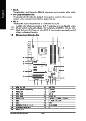
... 1 4 63 2 12 7 14 20 9 15 8 21 10 16 19 1) ATX_12V_2X 2) ATX (Power Connector) 3) PCIE_12V 4) CPU_FAN 5) SYS_FAN 6) PWR_FAN 7) FDD 8) IDE 9) SATAII0 / 1 / 2 / 3 / 4 / 5 10) GSATAII0 / GSATAII1 11) PWR_LED GA-965P-DQ6 Motherboard 5 18 17 11 13 12) BATTERY 13) F_PANEL 14) F_AUDIO 15) CD_IN 16) SPDIF_IN 17) F_USB1 / F_USB2 / F_USB3 18) F1_1394 / F2_1394 19) TPM 20) CLR_CMOS...
... 1 4 63 2 12 7 14 20 9 15 8 21 10 16 19 1) ATX_12V_2X 2) ATX (Power Connector) 3) PCIE_12V 4) CPU_FAN 5) SYS_FAN 6) PWR_FAN 7) FDD 8) IDE 9) SATAII0 / 1 / 2 / 3 / 4 / 5 10) GSATAII0 / GSATAII1 11) PWR_LED GA-965P-DQ6 Motherboard 5 18 17 11 13 12) BATTERY 13) F_PANEL 14) F_AUDIO 15) CD_IN 16) SPDIF_IN 17) F_USB1 / F_USB2 / F_USB3 18) F1_1394 / F2_1394 19) TPM 20) CLR_CMOS...
Manual
Page 21
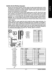
... power consumption be used that does not provide the required power, the result can lead to install a power supply that all the components on the motherboard. otherwise, please do not remove it. 8 4 5 1 ATX_12V_2X Pin No. 1 2 3 4 5 6 7 8 Definition GND GND GND GND +12V +12V +12V +12V 12 24 1 13 ATX Pin No. 1 2 ...provides a 24-pin ATX or 2x4 pin ATX 12V power connector, please remove the small cover on the power connector on the motherboard and connect tightly. Hardware Installation If the ATX 12V (2x4) power connector is unable to the CPU. Align the power connector ...
... power consumption be used that does not provide the required power, the result can lead to install a power supply that all the components on the motherboard. otherwise, please do not remove it. 8 4 5 1 ATX_12V_2X Pin No. 1 2 3 4 5 6 7 8 Definition GND GND GND GND +12V +12V +12V +12V 12 24 1 13 ATX Pin No. 1 2 ...provides a 24-pin ATX or 2x4 pin ATX 12V power connector, please remove the small cover on the power connector on the motherboard and connect tightly. Hardware Installation If the ATX 12V (2x4) power connector is unable to the CPU. Align the power connector ...
Manual
Page 22
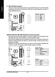
... this connector, or system instability may occur. 1 PIin No. Definition 1 GND 2 +12V / Speed Control 3 Sense 4 Speed Control 1 PWR_FAN PWR_FAN : Pin No. 1 2 3 Definition GND +12V Sense GA-965P-DQ6 Motherboard - 22 - Definition 1 NC 2 GND 3 GND 4 +12V 4/5/6) CPU_FAN / SYS_FAN / PWR_FAN (Cooler Fan Power Connector) The cooler fan power connector supplies a +12V power voltage via a 3-pin/4-pin...
... this connector, or system instability may occur. 1 PIin No. Definition 1 GND 2 +12V / Speed Control 3 Sense 4 Speed Control 1 PWR_FAN PWR_FAN : Pin No. 1 2 3 Definition GND +12V Sense GA-965P-DQ6 Motherboard - 22 - Definition 1 NC 2 GND 3 GND 4 +12V 4/5/6) CPU_FAN / SYS_FAN / PWR_FAN (Cooler Fan Power Connector) The cooler fan power connector supplies a +12V power voltage via a 3-pin/4-pin...
Manual
Page 24
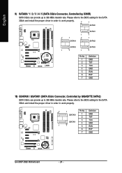
... install the proper driver in order to work properly. 7 1 Pin No. Definition GSATAII0 1 GND 2 TXP 3 TXN GSATAII1 4 GND 1 7 5 RXN 6 RXP 7 GND GA-965P-DQ6 Motherboard - 24 - English 9) SATAII0 / 1 / 2 / 3 / 4 / 5 (SATA 3Gb/s Connector, Controlled by GIGABYTE SATA2) SATA 3Gb/s can provide up to 300 MB/s transfer rate. Please refer to the BIOS setting for the SATA 3Gb...
... install the proper driver in order to work properly. 7 1 Pin No. Definition GSATAII0 1 GND 2 TXP 3 TXN GSATAII1 4 GND 1 7 5 RXN 6 RXP 7 GND GA-965P-DQ6 Motherboard - 24 - English 9) SATAII0 / 1 / 2 / 3 / 4 / 5 (SATA 3Gb/s Connector, Controlled by GIGABYTE SATA2) SATA 3Gb/s can provide up to 300 MB/s transfer rate. Please refer to the BIOS setting for the SATA 3Gb...

Manual
Page 26
...: Normal Close: Power On/Off Pin 1: Power Pin 2- Pin 3: NC Pin 4: Data(-) Pin 1: LED anode(+) Pin 2: LED cathode(-) Open: Normal Close: Reset Hardware System NC GA-965P-DQ6 Motherboard - 26 - Message LED/ Power/ Sleep LED Power Switch Speaker Connector MSG+ MSG- PW+ PWSPEAK+ SPEAK- 2 20 1 19 HD+ HD- of your chassis front panel to...
...: Normal Close: Power On/Off Pin 1: Power Pin 2- Pin 3: NC Pin 4: Data(-) Pin 1: LED anode(+) Pin 2: LED cathode(-) Open: Normal Close: Reset Hardware System NC GA-965P-DQ6 Motherboard - 26 - Message LED/ Power/ Sleep LED Power Switch Speaker Connector MSG+ MSG- PW+ PWSPEAK+ SPEAK- 2 20 1 19 HD+ HD- of your chassis front panel to...
Manual
Page 28
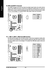
... contact your local dealer. 12 9 10 Pin No. 1 2 3 4 5 6 7 8 9 10 Definition Power (5V) Power (5V) USB DXUSB DyUSB DX+ USB Dy+ GND GND No Pin NC GA-965P-DQ6 Motherboard - 28 -
... contact your local dealer. 12 9 10 Pin No. 1 2 3 4 5 6 7 8 9 10 Definition Power (5V) Power (5V) USB DXUSB DyUSB DX+ USB Dy+ GND GND No Pin NC GA-965P-DQ6 Motherboard - 28 -


