Manual
Page 1
GA-945PL-DS3/ GA-945PL-S3 Intel® CoreTM 2 Extreme dual-core / CoreTM 2 Duo / Intel® Pentium® D / Pentium® 4 / Celeron® D LGA775 Processor Motherboard User's Manual Rev. 3301 12ME-945PLDS3-3301R * The WEEE marking on the product indicates this product must not be disposed of with user's other household waste and must be handed over to a designated collection point for the recycling of waste electrical and electronic equipment!! * The WEEE marking applies only in European Union's member states.
GA-945PL-DS3/ GA-945PL-S3 Intel® CoreTM 2 Extreme dual-core / CoreTM 2 Duo / Intel® Pentium® D / Pentium® 4 / Celeron® D LGA775 Processor Motherboard User's Manual Rev. 3301 12ME-945PLDS3-3301R * The WEEE marking on the product indicates this product must not be disposed of with user's other household waste and must be handed over to a designated collection point for the recycling of waste electrical and electronic equipment!! * The WEEE marking applies only in European Union's member states.
Manual
Page 2
Motherboard GA-945PL-DS3/GA-945PL-S3 Oct. 25, 2006 Motherboard GA-945PL-DS3/ GA-945PL-S3 Oct. 25, 2006
Motherboard GA-945PL-DS3/GA-945PL-S3 Oct. 25, 2006 Motherboard GA-945PL-DS3/ GA-945PL-S3 Oct. 25, 2006
Manual
Page 4
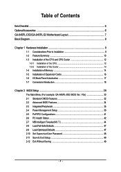
Table of Contents ItemChecklist ...6 OptionalAccessories ...6 GA-945PL-DS3/GA-945PL-S3 Motherboard Layout 7 Block Diagram ...8 Chapter 1 Hardware Installation 9 1-1 Considerations Prior to Installation 9 1-2 Feature Summary 10 1-3 Installation of the CPU...1-5 Installation of Expansion Cards 16 1-6 I/O Back Panel Introduction 17 1-7 Connectors Introduction 18 Chapter 2 BIOS Setup 29 The Main Menu (For example: GA-945PL-DS3 BIOS Ver.: F2e 30 2-1 Standard CMOS Features 32 2-2 Advanced BIOS Features 34 2-3 IntegratedPeripherals 36 2-4 Power Management Setup 39 2-5 PnP/PCI Configurations...
Table of Contents ItemChecklist ...6 OptionalAccessories ...6 GA-945PL-DS3/GA-945PL-S3 Motherboard Layout 7 Block Diagram ...8 Chapter 1 Hardware Installation 9 1-1 Considerations Prior to Installation 9 1-2 Feature Summary 10 1-3 Installation of the CPU...1-5 Installation of Expansion Cards 16 1-6 I/O Back Panel Introduction 17 1-7 Connectors Introduction 18 Chapter 2 BIOS Setup 29 The Main Menu (For example: GA-945PL-DS3 BIOS Ver.: F2e 30 2-1 Standard CMOS Features 32 2-2 Advanced BIOS Features 34 2-3 IntegratedPeripherals 36 2-4 Power Management Setup 39 2-5 PnP/PCI Configurations...
Manual
Page 7
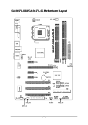
GA-945PL-DS3/GA-945PL-S3 Motherboard Layout KB_MS ATX_12V LGA775 CPU_FAN GA-945PL-DS3/GA-945PL-S3 COMA LPT ATX USB USB_LAN F_AUDIO AUDIO NB_FAN Intel® 945PL RTL 8111B PCIE_3 PCIE_16 DDRII1 DDRII2 DDRII3 DDRII4 PWR_FAN CODEC PCIE_1 PCIE_2 IT8718 CI CD_IN SYS _FAN SPDIF_IO CLR_CMOS BATTERY Intel® ICH7 PCI1 SATAII0 BIOS PCI2 SATAII1 PCI3 FDD F_USB2 SATAII2 SATAII3 IDE1 F_PANEL F_USB1 PWR_LED - 7 -
GA-945PL-DS3/GA-945PL-S3 Motherboard Layout KB_MS ATX_12V LGA775 CPU_FAN GA-945PL-DS3/GA-945PL-S3 COMA LPT ATX USB USB_LAN F_AUDIO AUDIO NB_FAN Intel® 945PL RTL 8111B PCIE_3 PCIE_16 DDRII1 DDRII2 DDRII3 DDRII4 PWR_FAN CODEC PCIE_1 PCIE_2 IT8718 CI CD_IN SYS _FAN SPDIF_IO CLR_CMOS BATTERY Intel® ICH7 PCI1 SATAII0 BIOS PCI2 SATAII1 PCI3 FDD F_USB2 SATAII2 SATAII3 IDE1 F_PANEL F_USB1 PWR_LED - 7 -
Manual
Page 9
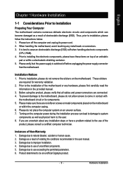
...read the information in the provided manual. 3. If you are no leftover screws or metal components placed on the motherboard. Damage due to be an unofficial Gigabyte product. - 9 - Hardware Installation Installation Notices 1. Damage as a result of uncertified components. 5. Product determined ... to use of Non-Warranty 1. English Chapter 1 Hardware Installation 1-1 Considerations Prior to Installation Preparing Your Computer The motherboard contains numerous delicate electronic circuits and components which can lead to damage to system components as well as physical harm ...
...read the information in the provided manual. 3. If you are no leftover screws or metal components placed on the motherboard. Damage due to be an unofficial Gigabyte product. - 9 - Hardware Installation Installation Notices 1. Damage as a result of uncertified components. 5. Product determined ... to use of Non-Warranty 1. English Chapter 1 Hardware Installation 1-1 Considerations Prior to Installation Preparing Your Computer The motherboard contains numerous delicate electronic circuits and components which can lead to damage to system components as well as physical harm ...
Manual
Page 10
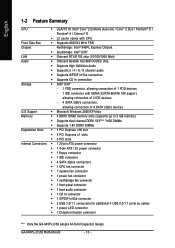
... Pentium® 4 / Celeron® D Š L2 cache varies with CPU Front Side Bus Š Supports 800/533 MHz FSB Chipset Northbridge: Intel® 945PL Express Chipset Š Southbridge: Intel® ICH7 LAN Š Onboard RTL8111B chip (10/100/1000 Mbit) Audio Š Onboard Realtek ALC888 CODEC chip Š Supports...PDIF In/Out connector Š 2 USB 2.0/1.1 connectors for additional 4 USB 2.0/1.1 ports by cables Š 1 power LED connector Š 1 Chassis Intrusion connector "*" Only the GA-945PL-DS3 adopts All-Solid Capacitor design. GA-945PL-(D)S3 Motherboard - 10 -
... Pentium® 4 / Celeron® D Š L2 cache varies with CPU Front Side Bus Š Supports 800/533 MHz FSB Chipset Northbridge: Intel® 945PL Express Chipset Š Southbridge: Intel® ICH7 LAN Š Onboard RTL8111B chip (10/100/1000 Mbit) Audio Š Onboard Realtek ALC888 CODEC chip Š Supports...PDIF In/Out connector Š 2 USB 2.0/1.1 connectors for additional 4 USB 2.0/1.1 ports by cables Š 1 power LED connector Š 1 Chassis Intrusion connector "*" Only the GA-945PL-DS3 adopts All-Solid Capacitor design. GA-945PL-(D)S3 Motherboard - 10 -
Manual
Page 11
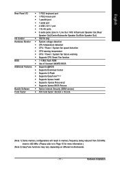
... reduced from 533 MHz down to 400 MHz. (Please refer to to Page 15 for more information.) (Note 2) EasyTune functions may vary depending on different motherboards. - 11 - Hardware Installation
... reduced from 533 MHz down to 400 MHz. (Please refer to to Page 15 for more information.) (Note 2) EasyTune functions may vary depending on different motherboards. - 11 - Hardware Installation
Manual
Page 12
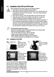
... of the following conditions: 1. Please set beyond the proper specifications, please do so according to the CPU during installation.) GA-945PL-(D)S3 Motherboard - 12 - HT functionality requirement content : Enabling the functionality of Hyper-Threading Technology for your computer system requires all of...insert properly. If you install the CPU in a straight and downwards motion. OS: An operation system that the motherboard supports the CPU. 2. CPU: An Intel® Pentium 4 Processor with the triangle and gently insert the CPU into its original position...
... of the following conditions: 1. Please set beyond the proper specifications, please do so according to the CPU during installation.) GA-945PL-(D)S3 Motherboard - 12 - HT functionality requirement content : Enabling the functionality of Hyper-Threading Technology for your computer system requires all of...insert properly. If you install the CPU in a straight and downwards motion. OS: An operation system that the motherboard supports the CPU. 2. CPU: An Intel® Pentium 4 Processor with the triangle and gently insert the CPU into its original position...
Manual
Page 13
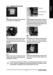
The CPU cooler may adhere to the pin hole on the motherboard.Pressing down the push pins diagonally. English 1-3-2 Installation of the Cooler Male ...of the CPU cooler to the CPU cooler installation section of the user manual) Fig. 5 Please check the back of motherboard after installing. Fig. 2 (Turning the push pin along the direction of arrow is to remove the CPU cooler, on... the contrary, is to install.) Please note the direction of arrow sign on the motherboard. If the push pin is only for Intel boxed fan) Fig. 3 Place the CPU cooler atop the CPU...
The CPU cooler may adhere to the pin hole on the motherboard.Pressing down the push pins diagonally. English 1-3-2 Installation of the Cooler Male ...of the CPU cooler to the CPU cooler installation section of the user manual) Fig. 5 Please check the back of motherboard after installing. Fig. 2 (Turning the push pin along the direction of arrow is to remove the CPU cooler, on... the contrary, is to install.) Please note the direction of arrow sign on the motherboard. If the push pin is only for Intel boxed fan) Fig. 3 Place the CPU cooler atop the CPU...
Manual
Page 14
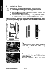
...that memory of similar capacity, specifications and brand be installed in only one direction. Memory modules have a foolproof insertion design. GA-945PL-(D)S3 Motherboard - 14 - The memory capacity used can be used is recommended that they can only fit in one direction. Fig.2...sockets to remove the DIMM module. Before installing or removing memory modules, please make sure that the memory used . 2. The motherboard supports DDRII memory modules, whereby BIOS will automatically detect memory capacity and specifications. A memory module can differ with the following conditions:...
...that memory of similar capacity, specifications and brand be installed in only one direction. Memory modules have a foolproof insertion design. GA-945PL-(D)S3 Motherboard - 14 - The memory capacity used can be used is recommended that they can only fit in one direction. Fig.2...sockets to remove the DIMM module. Before installing or removing memory modules, please make sure that the memory used . 2. The motherboard supports DDRII memory modules, whereby BIOS will automatically detect memory capacity and specifications. A memory module can differ with the following conditions:...
Manual
Page 16
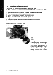
...of Expansion Cards You can install your computer's chassis cover. 7. Replace the screw to secure the slot bracket of the PCI Express x16 slot. GA-945PL-(D)S3 Motherboard - 16 - Press the expansion card firmly into the computer. 2. Be sure the metal contacts on the computer, if necessary, setup BIOS ... system. Make sure your computer's chassis cover, screws and slot bracket from the computer. 3. Power on the card are indeed seated in motherboard. 4. Installing a PCI Express x16 expansion card: Please align the VGA card to release the card. Remove your VGA card is locked by...
...of Expansion Cards You can install your computer's chassis cover. 7. Replace the screw to secure the slot bracket of the PCI Express x16 slot. GA-945PL-(D)S3 Motherboard - 16 - Press the expansion card firmly into the computer. 2. Be sure the metal contacts on the computer, if necessary, setup BIOS ... system. Make sure your computer's chassis cover, screws and slot bracket from the computer. 3. Power on the card are indeed seated in motherboard. 4. Installing a PCI Express x16 expansion card: Please align the VGA card to release the card. Remove your VGA card is locked by...
Manual
Page 18
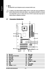
... audio setup steps for detailed software configuration information. 1-7 Connectors Introduction 1 3 6 11 16 13 14 4 1) ATX_12V 2) ATX (Power Connector) 3) CPU_FAN 4) SYS_FAN 5) PWR_FAN 6) NB_FAN 7) IDE1 8) FDD 9) SATAII0 / 1 / 2 / 3 GA-945PL-(D)S3 Motherboard 2 5 17 18 9 7 12 8 15 10 10) PWR_LED 11) F_AUDIO 12) F_PANEL 13) CD_IN 14) SPDIF_IO 15) F_USB1 / F_USB2 16) CI 17) CLR_CMOS 18) BATTERY - 18 -
... audio setup steps for detailed software configuration information. 1-7 Connectors Introduction 1 3 6 11 16 13 14 4 1) ATX_12V 2) ATX (Power Connector) 3) CPU_FAN 4) SYS_FAN 5) PWR_FAN 6) NB_FAN 7) IDE1 8) FDD 9) SATAII0 / 1 / 2 / 3 GA-945PL-(D)S3 Motherboard 2 5 17 18 9 7 12 8 15 10 10) PWR_LED 11) F_AUDIO 12) F_PANEL 13) CD_IN 14) SPDIF_IO 15) F_USB1 / F_USB2 16) CI 17) CLR_CMOS 18) BATTERY - 18 -

Manual
Page 19
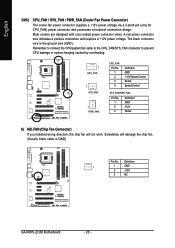
... Please use a power supply that is able to the CPU. Before connecting the power connector, please make sure that all the components on the motherboard. The ATX_12V power connector mainly supplies power to handle the system voltage requirements. otherwise, please do not remove it. 3 4 1 2 ATX_12V Pin...supply enough stable power to all components and devices are properly installed. Align the power connector with its proper location on the motherboard before plugging in the power cord; English 1/2) ATX_12V/ATX (Power Connector) With the use of the power connector, the ...
... Please use a power supply that is able to the CPU. Before connecting the power connector, please make sure that all the components on the motherboard. The ATX_12V power connector mainly supplies power to handle the system voltage requirements. otherwise, please do not remove it. 3 4 1 2 ATX_12V Pin...supply enough stable power to all components and devices are properly installed. Align the power connector with its proper location on the motherboard before plugging in the power cord; English 1/2) ATX_12V/ATX (Power Connector) With the use of the power connector, the ...
Manual
Page 20
A red power connector wire indicates a positive connection and requires a +12V power voltage. Definition 1 1 GND 2 +12V 3 NC GA-945PL-(D)S3 Motherboard - 20 - Sometimes will not work. Remember to connect the CPU/system fan cable to the CPU_FAN/SYS_FAN connector to prevent CPU damage or system hanging ...
A red power connector wire indicates a positive connection and requires a +12V power voltage. Definition 1 1 GND 2 +12V 3 NC GA-945PL-(D)S3 Motherboard - 20 - Sometimes will not work. Remember to connect the CPU/system fan cable to the CPU_FAN/SYS_FAN connector to prevent CPU damage or system hanging ...
Manual
Page 22
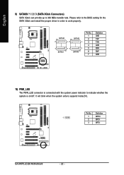
.../s and install the proper driver in order to 300 MB/s transfer rate. English 9) SATAII0 / 1 / 2 / 3 (SATA 3Gb/s Connectors) SATA 3Gb/s can provide up to work properly. GA-945PL-(D)S3 Motherboard - 22 - Definition 1 1 MPD+ 2 MPD- 3 MPD- It will blink when the system enters suspend mode(S1). Pin No. SATAII0 7 17 SATAII2 1 1 71 7 SATAII1 SATAII3 Pin No...
.../s and install the proper driver in order to 300 MB/s transfer rate. English 9) SATAII0 / 1 / 2 / 3 (SATA 3Gb/s Connectors) SATA 3Gb/s can provide up to work properly. GA-945PL-(D)S3 Motherboard - 22 - Definition 1 1 MPD+ 2 MPD- 3 MPD- It will blink when the system enters suspend mode(S1). Pin No. SATAII0 7 17 SATAII2 1 1 71 7 SATAII1 SATAII3 Pin No...
Manual
Page 24
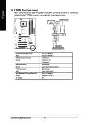
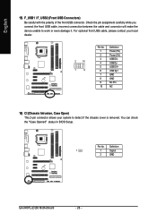
... MSG+ MSG- Pin 3: NC Pin 4: Data(-) Open: Normal Close: Reset Hardware System Open: Normal Close: Power On/Off Pin 1: LED anode(+) Pin 2: LED cathode(-) NC GA-945PL-(D)S3 Motherboard - 24 - PW+ PWSPEAK+ SPEAK- 2 20 1 19 HD+ HD- English 12) F_PANEL (Front Panel Jumper) Please connect the power LED, PC speaker, reset switch and power...
... MSG+ MSG- Pin 3: NC Pin 4: Data(-) Open: Normal Close: Reset Hardware System Open: Normal Close: Power On/Off Pin 1: LED anode(+) Pin 2: LED cathode(-) NC GA-945PL-(D)S3 Motherboard - 24 - PW+ PWSPEAK+ SPEAK- 2 20 1 19 HD+ HD- English 12) F_PANEL (Front Panel Jumper) Please connect the power LED, PC speaker, reset switch and power...
Manual
Page 26
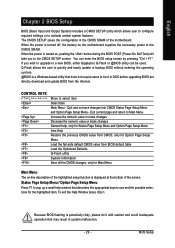
Definition 1 1 Signal 2 GND GA-945PL-(D)S3 Motherboard - 26 - You can check the "Case Opened" status in BIOS Setup. Pin No. For optional front USB cable, please contact your local dealer. 2 10 1 9 Pin ...
Definition 1 1 Signal 2 GND GA-945PL-(D)S3 Motherboard - 26 - You can check the "Case Opened" status in BIOS Setup. Pin No. For optional front USB cable, please contact your local dealer. 2 10 1 9 Pin ...

Manual
Page 28
English GA-945PL-(D)S3 Motherboard - 28 -
English GA-945PL-(D)S3 Motherboard - 28 -
Manual
Page 29
... numeric value or make changes Decrease the numeric value or make changes General help window that describes the appropriate keys to a new BIOS, either Gigabyte's Q-Flash or @BIOS utility can enter the BIOS setup screen by pressing "Ctrl + F1". Status Page Setup Menu / Option Page Setup...screen. BIOS Setup CONTROL KEYS Enter> Move to activate certain system features. You can be used. Because BIOS flashing is turned on the motherboard supplies the necessary power to pop up a small help , only for Status Page Setup Menu and Option Page Setup Menu Item Help ...
... numeric value or make changes Decrease the numeric value or make changes General help window that describes the appropriate keys to a new BIOS, either Gigabyte's Q-Flash or @BIOS utility can enter the BIOS setup screen by pressing "Ctrl + F1". Status Page Setup Menu / Option Page Setup...screen. BIOS Setup CONTROL KEYS Enter> Move to activate certain system features. You can be used. Because BIOS flashing is turned on the motherboard supplies the necessary power to pop up a small help , only for Status Page Setup Menu and Option Page Setup Menu Item Help ...

Manual
Page 30
Startup Screen: (For example: GA-945PL-DS3 BIOS Ver.: F2e) English :POST Screen :BIOS Setup/Q-Flash :XpressRecovery2 :Boot Menu
Startup Screen: (For example: GA-945PL-DS3 BIOS Ver.: F2e) English :POST Screen :BIOS Setup/Q-Flash :XpressRecovery2 :Boot Menu


