Manual
Page 6
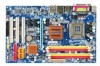
Item Checklist IDE Cable x 1, FDD Cable x 1 SATA 3Gb/s Cable x 2 I/O Shield * The items listed above are for reference only, and are subject to change without notice. Optional Accessories Š 2 Ports USB 2.0 Cable (Part Number: 12CR1-1UB030-51/R) Š 4 Ports USB 2.0 Cable (Part Number: 12CR1-1UB030-21/R) Š SPDIF In and Out Cable (Part Number: 12CR1-1SPINO-11/R) Š e-SATA Cable (Part Number: 12CF1-3SATPW-11R) - 6 -
Item Checklist IDE Cable x 1, FDD Cable x 1 SATA 3Gb/s Cable x 2 I/O Shield * The items listed above are for reference only, and are subject to change without notice. Optional Accessories Š 2 Ports USB 2.0 Cable (Part Number: 12CR1-1UB030-51/R) Š 4 Ports USB 2.0 Cable (Part Number: 12CR1-1UB030-21/R) Š SPDIF In and Out Cable (Part Number: 12CR1-1SPINO-11/R) Š e-SATA Cable (Part Number: 12CF1-3SATPW-11R) - 6 -
Manual
Page 9
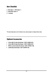
... of uncertified components. 5. Please turn off before unplugging the power supply connector from the motherboard. Please verify that all cables and power connectors are uncertain about any metal leads or connectors. 3. Installation Notices 1. Please do not allow screws to...not place the computer system on the motherboard. Damage due to come in the provided manual. 3. Damage due to be an unofficial Gigabyte product. - 9 - Product determined to use of electrostatic discharge (ESD). Hardware Installation Turning on the motherboard or within a electrostatic ...
... of uncertified components. 5. Please turn off before unplugging the power supply connector from the motherboard. Please verify that all cables and power connectors are uncertain about any metal leads or connectors. 3. Installation Notices 1. Please do not allow screws to...not place the computer system on the motherboard. Damage due to come in the provided manual. 3. Damage due to be an unofficial Gigabyte product. - 9 - Product determined to use of electrostatic discharge (ESD). Hardware Installation Turning on the motherboard or within a electrostatic ...
Manual
Page 10
... Š 1 front panel connector Š 1 front audio connector Š 1 CD In connector Š 1 S/PDIF In/Out connector Š 2 USB 2.0/1.1 connectors for additional 4 USB 2.0/1.1 ports by cables Š 1 power LED connector Š 1 Chassis Intrusion connector "*" Only the GA-945PL-DS3 adopts All-Solid Capacitor design.
... Š 1 front panel connector Š 1 front audio connector Š 1 CD In connector Š 1 S/PDIF In/Out connector Š 2 USB 2.0/1.1 connectors for additional 4 USB 2.0/1.1 ports by cables Š 1 power LED connector Š 1 Chassis Intrusion connector "*" Only the GA-945PL-DS3 adopts All-Solid Capacitor design.
Manual
Page 20
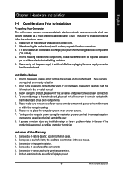
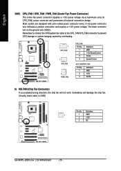
...connector wires. Sometimes will not work. The black connector wire is GND) Pin No. Remember to connect the CPU/system fan cable to the CPU_FAN/SYS_FAN connector to prevent CPU damage or system hanging caused by overheating. 1 CPU_FAN 1 SYS_FAN 1 PWR_FAN CPU_FAN...black cable is the ground wire (GND). English 3/4/5) CPU_FAN / SYS_FAN / PWR_FAN (Cooler Fan Power Connector) The cooler fan power connector supplies a +12V power voltage via a 3-pin/4-pin (only for CPU_FAN) power connector and possesses a foolproof connection design. Definition 1 1 GND 2 +12V 3 NC GA-945PL-(D)...
...connector wires. Sometimes will not work. The black connector wire is GND) Pin No. Remember to connect the CPU/system fan cable to the CPU_FAN/SYS_FAN connector to prevent CPU damage or system hanging caused by overheating. 1 CPU_FAN 1 SYS_FAN 1 PWR_FAN CPU_FAN...black cable is the ground wire (GND). English 3/4/5) CPU_FAN / SYS_FAN / PWR_FAN (Cooler Fan Power Connector) The cooler fan power connector supplies a +12V power voltage via a 3-pin/4-pin (only for CPU_FAN) power connector and possesses a foolproof connection design. Definition 1 1 GND 2 +12V 3 NC GA-945PL-(D)...
Manual
Page 21
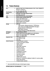
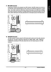
... two IDE devices (hard drive or optical drive). One IDE connector can then connect to the computer via an IDE connector. Before attaching the FDD cable, please take note of the foolproof groove in the IDE connector. 2 40 1 39 8) FDD (FDD Connector) The FDD connector is used to connect the FDD... cable while the other as Master and the other end of FDD drives supported are: 360KB, 720KB, 1.2MB, 1.44MB and 2.88MB. If you wish to connect ...
... two IDE devices (hard drive or optical drive). One IDE connector can then connect to the computer via an IDE connector. Before attaching the FDD cable, please take note of the foolproof groove in the IDE connector. 2 40 1 39 8) FDD (FDD Connector) The FDD connector is used to connect the FDD... cable while the other as Master and the other end of FDD drives supported are: 360KB, 720KB, 1.2MB, 1.44MB and 2.88MB. If you wish to connect ...
Manual
Page 25
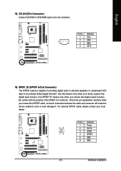
... In/Out Connector) The S/PDIF output is capable of the SPDIF_IO connector. Check the pin assignment carefully while you connect the S/PDIF cable, incorrect connection between the cable and connector will make the device unable to the connector. Use S/PDIF IN feature only when your stereo system has digital input function...audio out to work or even damage it. Hardware Installation Use this feature only when your device has digital output function. For optional S/PDIF cable, please contact your local dealer. 26 15 Pin No. 1 2 3 4 5 6 Definition Power No Pin SPDIF SPDIFI GND GND - 25...
... In/Out Connector) The S/PDIF output is capable of the SPDIF_IO connector. Check the pin assignment carefully while you connect the S/PDIF cable, incorrect connection between the cable and connector will make the device unable to the connector. Use S/PDIF IN feature only when your stereo system has digital input function...audio out to work or even damage it. Hardware Installation Use this feature only when your device has digital output function. For optional S/PDIF cable, please contact your local dealer. 26 15 Pin No. 1 2 3 4 5 6 Definition Power No Pin SPDIF SPDIFI GND GND - 25...
Manual
Page 26
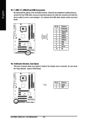
...2 GND GA-945PL-(D)S3 (rev. 2.0) Motherboard - 26 - English 15) F_USB1 / F_USB2 (Front USB Connectors) Be careful with the polarity of the front USB connector. Pin No. You can check the "Case Opened" status in BIOS Setup. Check the pin assignment carefully while you connect the front USB cable, incorrect connection... between the cable and connector will make the device unable to detect if the chassis cover is removed. For optional front USB...
...2 GND GA-945PL-(D)S3 (rev. 2.0) Motherboard - 26 - English 15) F_USB1 / F_USB2 (Front USB Connectors) Be careful with the polarity of the front USB connector. Pin No. You can check the "Case Opened" status in BIOS Setup. Check the pin assignment carefully while you connect the front USB cable, incorrect connection... between the cable and connector will make the device unable to detect if the chassis cover is removed. For optional front USB...
Manual
Page 37
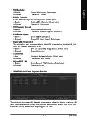
.... This feature will scan all USB storage devices. (Default value) Disabled Disable this function. Enabled BIOS will detect cabling issue and report the approximate distance to detect USB storage devices, including USB flash drives and USB hard drives during POST. ...Enabled Disabled Enable USB 2.0 Controller. (Default value) Disable USB 2.0 Controller. Refer to detect the status of the attached LAN cable. BIOS Setup USB Keyboard Support Enabled Enable USB Keyboard Support. Disabled Disable USB Keyboard Support. (Default value) USB Mouse Support Enabled...
.... This feature will scan all USB storage devices. (Default value) Disabled Disable this function. Enabled BIOS will detect cabling issue and report the approximate distance to detect USB storage devices, including USB flash drives and USB hard drives during POST. ...Enabled Disabled Enable USB 2.0 Controller. (Default value) Disable USB 2.0 Controller. Refer to detect the status of the attached LAN cable. BIOS Setup USB Keyboard Support Enabled Enable USB Keyboard Support. Disabled Disable USB Keyboard Support. (Default value) USB Mouse Support Enabled...
Manual
Page 38
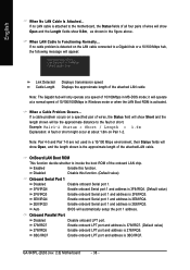
... or when the LAN Boot ROM is 2E8/IRQ3. GA-945PL-(D)S3 (rev. 2.0) Motherboard - 38 - OnBoard LAN Boot ROM This function decide whether to the fault or short. Link Detected --> 100Mbps Cable Length= 30m Link Detected Cable Length Displays transmission speed Displays the approximate length of wires..., the Status field will be the approximate distance to invoke the boot ROM of 10/100/1000Mbps in MS-DOS mode; When LAN Cable Is Functioning Normally... Auto BIOS will operate at about 1.6m on Pair 1-2. Example: Pair1-2 Status = Short / Length = 1.6m Explanation:...
... or when the LAN Boot ROM is 2E8/IRQ3. GA-945PL-(D)S3 (rev. 2.0) Motherboard - 38 - OnBoard LAN Boot ROM This function decide whether to the fault or short. Link Detected --> 100Mbps Cable Length= 30m Link Detected Cable Length Displays transmission speed Displays the approximate length of wires..., the Status field will be the approximate distance to invoke the boot ROM of 10/100/1000Mbps in MS-DOS mode; When LAN Cable Is Functioning Normally... Auto BIOS will operate at about 1.6m on Pair 1-2. Example: Pair1-2 Status = Short / Length = 1.6m Explanation:...

Manual
Page 43
...to PWM when you installed and sets the optimal CPU Smart FAN control mode for CPU fans with a 4-pin fan power cable. However, some 4-pin CPU fan power cables are not designed following Intel 4-Wire fans PWM control specifications. Note: In fact, the Voltage option can adjust the fan speed... Smart FAN Control Disabled Disable this function is enabled. PWM Set to Voltage when you use a CPU fan with 3-pin or 4-pin power cables. With such CPU fans, selecting PWM will run at different speed depending on their requirements. (Default Value) CPU Smart FAN Mode This option is...
...to PWM when you installed and sets the optimal CPU Smart FAN control mode for CPU fans with a 4-pin fan power cable. However, some 4-pin CPU fan power cables are not designed following Intel 4-Wire fans PWM control specifications. Note: In fact, the Voltage option can adjust the fan speed... Smart FAN Control Disabled Disable this function is enabled. PWM Set to Voltage when you use a CPU fan with 3-pin or 4-pin power cables. With such CPU fans, selecting PWM will run at different speed depending on their requirements. (Default Value) CPU Smart FAN Mode This option is...


