
User Manual
Page 7
English PnP/PCI Configurations 41 PC Health Status 42 Frequency/Voltage Control 43 Load Fail-Safe Defaults 45 Load Optimized Defaults 46 Set Supervisor/User Password 47 Save & Exit Setup 48 Exit Without Saving 49 Chapter 4 Technical Reference 51 @BIOS™ Introduction 51 EasyTune™ 4 Introduction 52 Flash BIOS Method Introduction 53 Method 1 : Q-Flash 53 Method 2 : @BIOS Utility 66 6-Channel Audio Function Introduction 68 Xpress Recovery Introduction 71 Chapter 5 Appendix 75 - 3 - Table of Content
English PnP/PCI Configurations 41 PC Health Status 42 Frequency/Voltage Control 43 Load Fail-Safe Defaults 45 Load Optimized Defaults 46 Set Supervisor/User Password 47 Save & Exit Setup 48 Exit Without Saving 49 Chapter 4 Technical Reference 51 @BIOS™ Introduction 51 EasyTune™ 4 Introduction 52 Flash BIOS Method Introduction 53 Method 1 : Q-Flash 53 Method 2 : @BIOS Utility 66 6-Channel Audio Function Introduction 68 Xpress Recovery Introduction 71 Chapter 5 Appendix 75 - 3 - Table of Content
User Manual
Page 8
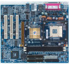
...cable x 1) 2 Port USB Cable x 1 4 Port USB Cable x 1 SPDIF-KIT x 1 (SPDIF Out KIT) IEEE 1394 Cable x1 Audio Combo Kit x 1 (SURROUND-Kit + SPDIF Out KIT) Motherboard Settings Label SATA RAID Manual SATA cable x 1 WARNING! Computer motherboards and expansion ... Motherboard - 4 - Place components on a grounded antistatic pad or on your computer. 1. English Item Checklist The GA-8VM533 motherboard IDE cable x 1 / Floppy cable x 1 CD for motherboard driver & utility GA-8VM533 user's manual I/O Shield Quick PC Installation Guide RAID Manual GC-SATA Card (Optional) (M anual; Ensure that the...
...cable x 1) 2 Port USB Cable x 1 4 Port USB Cable x 1 SPDIF-KIT x 1 (SPDIF Out KIT) IEEE 1394 Cable x1 Audio Combo Kit x 1 (SURROUND-Kit + SPDIF Out KIT) Motherboard Settings Label SATA RAID Manual SATA cable x 1 WARNING! Computer motherboards and expansion ... Motherboard - 4 - Place components on a grounded antistatic pad or on your computer. 1. English Item Checklist The GA-8VM533 motherboard IDE cable x 1 / Floppy cable x 1 CD for motherboard driver & utility GA-8VM533 user's manual I/O Shield Quick PC Installation Guide RAID Manual GC-SATA Card (Optional) (M anual; Ensure that the...
User Manual
Page 22
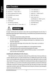
...MICOut". Please note: You are ableto use2-/6-channelaudio feature by S/W selection. GA-8VM533 Motherboard - 18 - Method1: Connect"FrontSpeaker" to "Line Out" Connect"Rear Speaker" to "Line In" Connect "Centerand Subwoofer" to Line-In jack. x Audio Connectors Line In(Rear Speaker) Line Out(FrontSpeaker) MIC In(Center and ... you connect your device(s) into USB connector(s), please make sure your OS does not support USB controller, please contactOSvendor for 6-channel audio setup installation, please refer to page 68. If you want to ena ble 6 -cha nnel function, you want the detail...
...MICOut". Please note: You are ableto use2-/6-channelaudio feature by S/W selection. GA-8VM533 Motherboard - 18 - Method1: Connect"FrontSpeaker" to "Line Out" Connect"Rear Speaker" to "Line In" Connect "Centerand Subwoofer" to Line-In jack. x Audio Connectors Line In(Rear Speaker) Line Out(FrontSpeaker) MIC In(Center and ... you connect your device(s) into USB connector(s), please make sure your OS does not support USB controller, please contactOSvendor for 6-channel audio setup installation, please refer to page 68. If you want to ena ble 6 -cha nnel function, you want the detail...
User Manual
Page 28
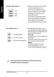
... /off. Pin No. Please note, you are buying support front audio connector, please contact your chassis must have the alternative of using front audio connector or of using rear audio connector to indicate whether the system is on the MB header. English... 8) PWR_LED PWR_LED is connect with the system power indicator to play sound. 10 9 21 Pin No. 1 2 3 4 5 6 7 8 9 10 Definition MIC GND REF Power FrontAudio (R) RearAudio (R) Reserved No Pin FrontAudio (L) RearAudio (L) GA...
... /off. Pin No. Please note, you are buying support front audio connector, please contact your chassis must have the alternative of using front audio connector or of using rear audio connector to indicate whether the system is on the MB header. English... 8) PWR_LED PWR_LED is connect with the system power indicator to play sound. 10 9 21 Pin No. 1 2 3 4 5 6 7 8 9 10 Definition MIC GND REF Power FrontAudio (R) RearAudio (R) Reserved No Pin FrontAudio (L) RearAudio (L) GA...

User Manual
Page 29
English 10) CD_IN (CD In Connector) Connect CD-ROM or DVD-ROM audio out to the connector. Check the pin assignment while you connect the front USB cable. Pin No. Please contact your nearest dealer for optional front USB cable. 2 10 2 10 F_ US B1 F_ US B2 19 19 Pin No. 1 2 3 4 5 6 7 8 9 10 Definition Power Power USB DxUSB DyUSB Dx+ USB Dy+ GND GND No Pin NC - 25 - Definition 1 CD-L 1 2 GND 3 GND 4 CD-R 11) F_USB1 / F_USB2 (Front USB Connector, Yellow) Be careful with the polarity of the front USB connector. Hardware Installation Process
English 10) CD_IN (CD In Connector) Connect CD-ROM or DVD-ROM audio out to the connector. Check the pin assignment while you connect the front USB cable. Pin No. Please contact your nearest dealer for optional front USB cable. 2 10 2 10 F_ US B1 F_ US B2 19 19 Pin No. 1 2 3 4 5 6 7 8 9 10 Definition Power Power USB DxUSB DyUSB Dx+ USB Dy+ GND GND No Pin NC - 25 - Definition 1 CD-L 1 2 GND 3 GND 4 CD-R 11) F_USB1 / F_USB2 (Front USB Connector, Yellow) Be careful with the polarity of the front USB connector. Hardware Installation Process

User Manual
Page 39
... Utility -Copy right (C) 1984-2003 Aw ard Softw are Integrated Peripherals OnChip IDE Channel0 [Enabled] Item Help OnChip IDE Channel1 [Enabled] Menu Lev el u AC97 Audio [Auto] If a hard disk VIA onboard LAN [Enabled] controller card is USB 1.1 Controller USB 2.0 Controller USB Key board Support USB Mouse Support Onboard Serial Port...
... Utility -Copy right (C) 1984-2003 Aw ard Softw are Integrated Peripherals OnChip IDE Channel0 [Enabled] Item Help OnChip IDE Channel1 [Enabled] Menu Lev el u AC97 Audio [Auto] If a hard disk VIA onboard LAN [Enabled] controller card is USB 1.1 Controller USB 2.0 Controller USB Key board Support USB Mouse Support Onboard Serial Port...
User Manual
Page 40
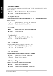
...Controller. (Default value) Disabled Disable USB1.1 Controller. Enabled Enable USB Keyboard Support. Disabled Disable USB Keyboard Support. (Default value) GA-8VM533 Motherboard - 36 - VIA onboard LAN Enable Enable onboard LAN function.(Default value) Disable Disable onboard LAN function. English OnChip... Auto Enable onboard 2nd channel IDE port. (Default value) Disabled Disable onboard 2nd channel IDE port. AC97 Audio Auto Enable onboard AC'97 audio function. (Default Value) Disabled Disable this option if you are not using the onboard USB 2.0 feature. ...
...Controller. (Default value) Disabled Disable USB1.1 Controller. Enabled Enable USB Keyboard Support. Disabled Disable USB Keyboard Support. (Default value) GA-8VM533 Motherboard - 36 - VIA onboard LAN Enable Enable onboard LAN function.(Default value) Disable Disable onboard LAN function. English OnChip... Auto Enable onboard 2nd channel IDE port. (Default value) Disabled Disable onboard 2nd channel IDE port. AC97 Audio Auto Enable onboard AC'97 audio function. (Default Value) Disabled Disable this option if you are not using the onboard USB 2.0 feature. ...

User Manual
Page 72
...audio output without any additional module. Line In M IC In Line Out STEP 2 : After installation of the screen. Basic 6 Channel Analog Audio Output Mode Use the back audio panel to install the function! Right click the audio... icon "Volum e" from the windows tray at the bottom of the audio driver, you...Audio Pro pertie s". STEP 1 : Connect the front channels to "Line Out", the rear channels to "Line In", and the Center/Subwoofer channels to "MIC In". English 6-Channel Audio...
...audio output without any additional module. Line In M IC In Line Out STEP 2 : After installation of the screen. Basic 6 Channel Analog Audio Output Mode Use the back audio panel to install the function! Right click the audio... icon "Volum e" from the windows tray at the bottom of the audio driver, you...Audio Pro pertie s". STEP 1 : Connect the front channels to "Line Out", the rear channels to "Line In", and the Center/Subwoofer channels to "MIC In". English 6-Channel Audio...

User Manual
Page 73
English STEP 4 : Choose the "5.1 surround sound speakers" and click "OK". STEP 5 : You'll find an icon on the taskbar's status area. Click the audio icon "Volume" from the windows tray at the bottom of the screen. Technical Reference STEP 7 : Click "Advanced". - 69 - STEP 6 : Click Options\Advanced Controls.
English STEP 4 : Choose the "5.1 surround sound speakers" and click "OK". STEP 5 : You'll find an icon on the taskbar's status area. Click the audio icon "Volume" from the windows tray at the bottom of the screen. Technical Reference STEP 7 : Click "Advanced". - 69 - STEP 6 : Click Options\Advanced Controls.
User Manual
Page 80
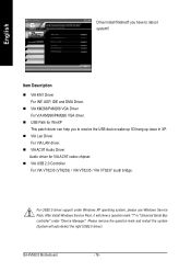
...Driver For VIA KM266/P4M266 VGA driver. in XP. you to reboot system!! n USB Path for VIA AC97 codec chipset. n VIA AC97 Audio Driver Audio driver for WinXP This patch driver can help you have to resolve the USB device wake up S3 hang up issue in "Universal Serial Bus... controller" under Windows XP operating system, please use Windows Service Pack. English Driver install finished!! For USB2.0 driver support under "Device Manager". GA-8VM533 ...
...Driver For VIA KM266/P4M266 VGA driver. in XP. you to reboot system!! n USB Path for VIA AC97 codec chipset. n VIA AC97 Audio Driver Audio driver for WinXP This patch driver can help you have to resolve the USB device wake up S3 hang up issue in "Universal Serial Bus... controller" under Windows XP operating system, please use Windows Service Pack. English Driver install finished!! For USB2.0 driver support under "Device Manager". GA-8VM533 ...

User Manual
Page 90
GA-8VM533 Motherboard - 86 - English Acronyms Acronyms ACPI APM AGP AMR ACR BIOS CPU CMOS CRIMM CNR DMA DMI DIMM DRM DRAM DDR ECP ESCD ECC EMC EPP ESD FDD FSB HDD IDE IRQ Meaning Advanced Configuration and Power Interface Advanced Power Management Accelerated Graphics Port Audio Modem Riser Advanced Communications Riser Basic...
GA-8VM533 Motherboard - 86 - English Acronyms Acronyms ACPI APM AGP AMR ACR BIOS CPU CMOS CRIMM CNR DMA DMI DIMM DRM DRAM DDR ECP ESCD ECC EMC EPP ESD FDD FSB HDD IDE IRQ Meaning Advanced Configuration and Power Interface Advanced Power Management Accelerated Graphics Port Audio Modem Riser Advanced Communications Riser Basic...


