
Manual
Page 1
GA-8S661FXM-775 Intel® Pentium® 4 LGA775 Processor Motherboard User's Manual Rev. 1102 12ME-61FXM775-1102
GA-8S661FXM-775 Intel® Pentium® 4 LGA775 Processor Motherboard User's Manual Rev. 1102 12ME-61FXM775-1102

Manual
Page 2
Motherboard GA-8S661FXM-775 Sept. 29, 2004 Motherboard GA-8S661FXM-775 Sept. 29, 2004
Motherboard GA-8S661FXM-775 Sept. 29, 2004 Motherboard GA-8S661FXM-775 Sept. 29, 2004
Manual
Page 4
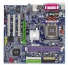
Table of Contents GA-8S661FXM-775 Motherboard Layout 6 Block Diagram ...7 Chapter 1 Hardware Installation 9 1-1 Considerations Prior to Installation 9 1-2 Feature Summary 10 1-3 Installation of the CPU and Heatsink 12 1-3-1 Installation of the CPU 12 1-3-2 ...
Table of Contents GA-8S661FXM-775 Motherboard Layout 6 Block Diagram ...7 Chapter 1 Hardware Installation 9 1-1 Considerations Prior to Installation 9 1-2 Feature Summary 10 1-3 Installation of the CPU and Heatsink 12 1-3-1 Installation of the CPU 12 1-3-2 ...

Manual
Page 9
... below: 1. Damage due to be an unofficial Gigabyte product. - 9 - Damage due to use of uncertified components. 5. Prior to installing the electronic components, please have a problem related to the use of the motherboard or any hardware, please first carefully read the ...validation. 2. These stickers are connected. 4. English Chapter 1 Hardware Installation 1-1 Considerations Prior to Installation Preparing Your Computer The motherboard contains numerous delicate electronic circuits and components which can lead to damage to system components as well as a result of ...
... below: 1. Damage due to be an unofficial Gigabyte product. - 9 - Damage due to use of uncertified components. 5. Prior to installing the electronic components, please have a problem related to the use of the motherboard or any hardware, please first carefully read the ...validation. 2. These stickers are connected. 4. English Chapter 1 Hardware Installation 1-1 Considerations Prior to Installation Preparing Your Computer The motherboard contains numerous delicate electronic circuits and components which can lead to damage to system components as well as a result of ...
Manual
Page 10
...; Supports Jack-Sensing function Š IT8705AF Š CPU / System fan speed detection Š System voltage detection Š CPU temperature detection Š CPU Smart Fan Control GA-8S661FXM-775 Motherboard - 10 - English 1-2 Feature Summary CPU Chipset Memory Slots IDE Connections Onboard SATA FDD Connections Peripherals Onboard VGA Onboard LAN Onboard Audio I/O Control Hardware Monitor Š...
...; Supports Jack-Sensing function Š IT8705AF Š CPU / System fan speed detection Š System voltage detection Š CPU temperature detection Š CPU Smart Fan Control GA-8S661FXM-775 Motherboard - 10 - English 1-2 Feature Summary CPU Chipset Memory Slots IDE Connections Onboard SATA FDD Connections Peripherals Onboard VGA Onboard LAN Onboard Audio I/O Control Hardware Monitor Š...
Manual
Page 12
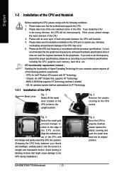
... and heatsink. 4. Fig. 4 Once the CPU is installed on the CPU socket to the CPU during installation.) GA-8S661FXM-775 Motherboard - 12 - Please make sure that supports HT Technology - Chipset: An SiS® Chipset that the motherboard supports the CPU. 2. Align the indented corner of the CPU with the triangle and gently insert the CPU...
... and heatsink. 4. Fig. 4 Once the CPU is installed on the CPU socket to the CPU during installation.) GA-8S661FXM-775 Motherboard - 12 - Please make sure that supports HT Technology - Chipset: An SiS® Chipset that the motherboard supports the CPU. 2. Align the indented corner of the CPU with the triangle and gently insert the CPU...
Manual
Page 13
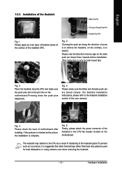
... Finally, please attach the power connector of the heatsink to the heatsink installation section of the user manual) Fig. 5 Please check the back of motherboard after installing. Hardware Installation If the push pin is inserted as a result of hardening of the heatsink paste.To prevent such an occurrence, it is... Heatsink Male Push Pin The top of Female Push Pin Female Push Pin Fig.1 Please apply an even layer of heatsink paste on the motherboard. The heatsink may adhere to install.) Please note the direction of arrow is to remove the heatsink, on the contrary, is to the...
... Finally, please attach the power connector of the heatsink to the heatsink installation section of the user manual) Fig. 5 Please check the back of motherboard after installing. Hardware Installation If the push pin is inserted as a result of hardening of the heatsink paste.To prevent such an occurrence, it is... Heatsink Male Push Pin The top of Female Push Pin Female Push Pin Fig.1 Please apply an even layer of heatsink paste on the motherboard. The heatsink may adhere to install.) Please note the direction of arrow is to remove the heatsink, on the contrary, is to the...

Manual
Page 14
... the DIMM memory module vertically into the DIMM socket. DDR memory module Fig. 1 Fig. 2 GA-8S661FXM-775 Motherboard - 14 - Memory modules have a foolproof insertion design. A memory module can only fit in one direction. To install the memory module, just push it down. Then .... Memory size can only fit in one direction. Fig.2 Close the plastic clip at both edges of the DIMM sockets to prevent hardware damage. 3. The motherboard has 2 dual inline memory module (DIMM) sockets.
... the DIMM memory module vertically into the DIMM socket. DDR memory module Fig. 1 Fig. 2 GA-8S661FXM-775 Motherboard - 14 - Memory modules have a foolproof insertion design. A memory module can only fit in one direction. To install the memory module, just push it down. Then .... Memory size can only fit in one direction. Fig.2 Close the plastic clip at both edges of the DIMM sockets to prevent hardware damage. 3. The motherboard has 2 dual inline memory module (DIMM) sockets.
Manual
Page 15
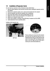
... into expansion slot in the slot. 5. Replace the screw to the onboard AGP slot and press firmly down on the card are indeed seated in motherboard. 4. Make sure your VGA card is locked by following the steps outlined below: 1. Installing a AGP expansion card: AGP Card Please carefully pull out the small...
... into expansion slot in the slot. 5. Replace the screw to the onboard AGP slot and press firmly down on the card are indeed seated in motherboard. 4. Make sure your VGA card is locked by following the steps outlined below: 1. Installing a AGP expansion card: AGP Card Please carefully pull out the small...
Manual
Page 16
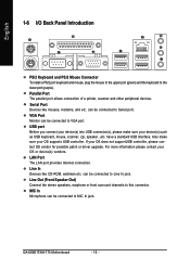
...(s) into USB connector(s), please make sure your device(s) such as USB keyboard, mouse, scanner, zip, speaker...etc. Also make sure your OS supports USB controller. GA-8S661FXM-775 Motherboard - 16 - Parallel Port The parallel port allows connection of a printer, scanner and other peripheral devices. VGA Port Monitor can be connected to Line In jack...
...(s) into USB connector(s), please make sure your device(s) such as USB keyboard, mouse, scanner, zip, speaker...etc. Also make sure your OS supports USB controller. GA-8S661FXM-775 Motherboard - 16 - Parallel Port The parallel port allows connection of a printer, scanner and other peripheral devices. VGA Port Monitor can be connected to Line In jack...
Manual
Page 18
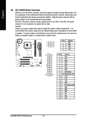
... connector is able to all components and devices are properly installed. Before connecting the power connector, please make sure that all the components on the motherboard. Caution! Definition 4 2 1 GND 3 1 2 GND 3 +12V 4 +12V 11 1 Pin No. It is unable to the CPU. Definition 1 3.3V 2 3.3V 3 ... 14 PS_ON (soft on the motherboard and connect tightly. If a power supply is used (300W or greater). Align the power connector with its proper location on /off) 15 GND 16 GND 17 GND 18 -5V 19 VCC 20 VCC GA-8S661FXM-775 Motherboard - 18 - Pin No.
... connector is able to all components and devices are properly installed. Before connecting the power connector, please make sure that all the components on the motherboard. Caution! Definition 4 2 1 GND 3 1 2 GND 3 +12V 4 +12V 11 1 Pin No. It is unable to the CPU. Definition 1 3.3V 2 3.3V 3 ... 14 PS_ON (soft on the motherboard and connect tightly. If a power supply is used (300W or greater). Align the power connector with its proper location on /off) 15 GND 16 GND 17 GND 18 -5V 19 VCC 20 VCC GA-8S661FXM-775 Motherboard - 18 - Pin No.
Manual
Page 20
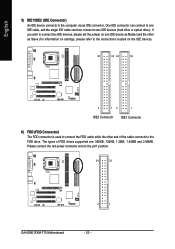
... IDE device). 40 39 40 39 2 12 1 IDE2 Connector IDE1 Connector 6) FDD (FDD Connector) The FDD connector is used to the pin1 position. 34 33 2 1 GA-8S661FXM-775 Motherboard - 20 -
... IDE device). 40 39 40 39 2 12 1 IDE2 Connector IDE1 Connector 6) FDD (FDD Connector) The FDD connector is used to the pin1 position. 34 33 2 1 GA-8S661FXM-775 Motherboard - 20 -
Manual
Page 22
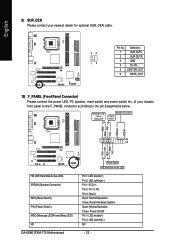
...+ HD- RESRES+ NC HD (IDE Hard Disk Active LED) SPEAK (Speaker Connector) RES (Reset Switch) PW (Power Switch) MSG (Message LED/Power/Sleep LED) NC GA-8S661FXM-775 Motherboard Reset Switch IDE Hard Disk Active LED Pin 1: LED anode(+) Pin 2: LED cathode(-) Pin 1: VCC(+) Pin 2- Message LED/ Power/ Sleep LED Speaker Connector Power Switch...
...+ HD- RESRES+ NC HD (IDE Hard Disk Active LED) SPEAK (Speaker Connector) RES (Reset Switch) PW (Power Switch) MSG (Message LED/Power/Sleep LED) NC GA-8S661FXM-775 Motherboard Reset Switch IDE Hard Disk Active LED Pin 1: LED anode(+) Pin 2: LED cathode(-) Pin 1: VCC(+) Pin 2- Message LED/ Power/ Sleep LED Speaker Connector Power Switch...
Manual
Page 24
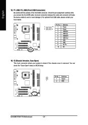
... cover is removed. Pin No. English 13) F1_USB / F2_USB (Front USB Connectors) Be careful with the polarity of the front USB connector. Definition 1 Signal 1 2 GND GA-8S661FXM-775 Motherboard - 24 - You can check the "Case Open" status in BIOS Setup. Pin No. For optional front USB cable, please contact your system to work or...
... cover is removed. Pin No. English 13) F1_USB / F2_USB (Front USB Connectors) Be careful with the polarity of the front USB connector. Definition 1 Signal 1 2 GND GA-8S661FXM-775 Motherboard - 24 - You can check the "Case Open" status in BIOS Setup. Pin No. For optional front USB cable, please contact your system to work or...

Manual
Page 26
.... 4. It will blink when the system enters suspend mode. Turn OFF the computer and unplug the power cord. 2. Definition 1 MPD+ 1 2 MPD- 3 MPD- 18) BAT (Battery) GA-8S661FXM-775 Motherboard Danger of used batteries according to erase CMOS... 1.
.... 4. It will blink when the system enters suspend mode. Turn OFF the computer and unplug the power cord. 2. Definition 1 MPD+ 1 2 MPD- 3 MPD- 18) BAT (Battery) GA-8S661FXM-775 Motherboard Danger of used batteries according to erase CMOS... 1.

Manual
Page 28
English GA-8S661FXM-775 Motherboard - 28 -
English GA-8S661FXM-775 Motherboard - 28 -
Manual
Page 29
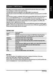
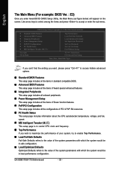
...function is turned on, pushing the button during the BIOS POST (Power-On Self Test) will take you wish to upgrade to a new BIOS, either Gigabyte's Q-Flash or @BIOS utility can enter the BIOS setup screen by pressing "Ctrl + F1". You can be reset to DOS before upgrading BIOS but ... all the CMOS changes, only for the highlighted item. If you to use and the possible selections for Main Menu Main Menu The on the motherboard supplies the necessary power to activate certain system features. When setting up a small help , only for Status Page Setup Menu and Option Page Setup ...
...function is turned on, pushing the button during the BIOS POST (Power-On Self Test) will take you wish to upgrade to a new BIOS, either Gigabyte's Q-Flash or @BIOS utility can enter the BIOS setup screen by pressing "Ctrl + F1". You can be reset to DOS before upgrading BIOS but ... all the CMOS changes, only for the highlighted item. If you to use and the possible selections for Main Menu Main Menu The on the motherboard supplies the necessary power to activate certain system features. When setting up a small help , only for Status Page Setup Menu and Option Page Setup ...
Manual
Page 30
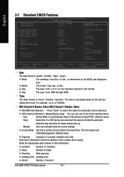
GA-8S661FXM-775 Motherboard - 30 - If you can't find the setting you want, please press "Ctrl+F1" to access hidden advanced options. „ Standard CMOS Features This setup page ...
GA-8S661FXM-775 Motherboard - 30 - If you can't find the setting you want, please press "Ctrl+F1" to access hidden advanced options. „ Standard CMOS Features This setup page ...
Manual
Page 32
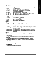
..., Slave IDE HDD Auto-Detection Press "Enter" to select this if no IDE devices are : CHS/LBA/Large/Auto (Default:Auto) Capacity Capacity of sectors GA-8S661FXM-775 Motherboard - 32 - Hard drive information should be labeled on the 24-hour military-time clock. to Dec. to Sat. Week The weekday, from 1999 through 2098...
..., Slave IDE HDD Auto-Detection Press "Enter" to select this if no IDE devices are : CHS/LBA/Large/Auto (Default:Auto) Capacity Capacity of sectors GA-8S661FXM-775 Motherboard - 32 - Hard drive information should be labeled on the 24-hour military-time clock. to Dec. to Sat. Week The weekday, from 1999 through 2098...
Manual
Page 33
...high-density drive; 1.2M byte capacity 720K, 3.5" (3.5 inch when 3 Mode is typically 512K for systems with 512K memory installed on the motherboard, or 640K for systems with 640K or more memory installed on The category determines whether the computer will stop for all other errors. Base Memory... system boot will determine the amount of base (or conventional) memory installed in the computer. it will be prompted. Halt on the motherboard. it will stop for any error that may be stopped. BIOS Setup All Errors Whenever the BIOS detects a non-fatal error the ...
...high-density drive; 1.2M byte capacity 720K, 3.5" (3.5 inch when 3 Mode is typically 512K for systems with 512K memory installed on the motherboard, or 640K for systems with 640K or more memory installed on The category determines whether the computer will stop for all other errors. Base Memory... system boot will determine the amount of base (or conventional) memory installed in the computer. it will be prompted. Halt on the motherboard. it will stop for any error that may be stopped. BIOS Setup All Errors Whenever the BIOS detects a non-fatal error the ...


