
Manual
Page 2
...array, press ENTER on your computer and press Del to create RAID array on the motherboard. Ác Configuring SATA Hard Drive(s) (Controller: nVIDIA nForce4 SLI) Åé ¤¤ ¤å To configure SATA hard drive(s), follow the steps below: (1) Install SATA hard drive(s) in your ...power supply to available SATA port(s) on the SATA controller. SATA Configurations (P4 nForce4 SLI series) - 2 - In the example in Figure 1, make sure that you may refer to the motherboard user's manual to create RAID, you use two hard drives with identical model and capacity). Before ...
...array, press ENTER on your computer and press Del to create RAID array on the motherboard. Ác Configuring SATA Hard Drive(s) (Controller: nVIDIA nForce4 SLI) Åé ¤¤ ¤å To configure SATA hard drive(s), follow the steps below: (1) Install SATA hard drive(s) in your ...power supply to available SATA port(s) on the SATA controller. SATA Configurations (P4 nForce4 SLI series) - 2 - In the example in Figure 1, make sure that you may refer to the motherboard user's manual to create RAID, you use two hard drives with identical model and capacity). Before ...
Manual
Page 6
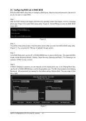
You can manually set the striping block size. The following is from 4K to 128K. In the Striping Block field, use the UP or DOWN ARROW key to ... Array Disks Loc Disk Model Name [g] Add [f ] Del [ESC] Quit [F6] Back [F7] Finish [TAB] Navigate [hi] Select [ENTER] Popup Figure 7 SATA Configurations (P4 nForce4 SLI series) - 6 - Hit the F10 key to set the Striping Block size. Press F10 to select a RAID mode. Figure 6 Step 2 The Define a New Array screen is...
You can manually set the striping block size. The following is from 4K to 128K. In the Striping Block field, use the UP or DOWN ARROW key to ... Array Disks Loc Disk Model Name [g] Add [f ] Del [ESC] Quit [F6] Back [F7] Finish [TAB] Navigate [hi] Select [ENTER] Popup Figure 7 SATA Configurations (P4 nForce4 SLI series) - 6 - Hit the F10 key to set the Striping Block size. Press F10 to select a RAID mode. Figure 6 Step 2 The Define a New Array screen is...
Manual
Page 11
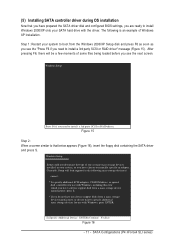
... to install a 3rd party SCSI or RAID driver. S=Specify Additional Device ENTER=Continue F3=Exit Figure 16 - 11 - SATA Configurations (P4 nForce4 SLI series) Windows Setup Press F6 if you need to install Windows 2000/XP onto your SATA hard drive with Windows, press ENTER. Currently, Setup will...an example of one or more mass storage devices installed in your system to boot from a mass storage device manufacturer, or do not want to manually specify an adapter. After pressing F6, there will load support for which you have a device support disk from a mass storage device manufacturer, ...
... to install a 3rd party SCSI or RAID driver. S=Specify Additional Device ENTER=Continue F3=Exit Figure 16 - 11 - SATA Configurations (P4 nForce4 SLI series) Windows Setup Press F6 if you need to install Windows 2000/XP onto your SATA hard drive with Windows, press ENTER. Currently, Setup will...an example of one or more mass storage devices installed in your system to boot from a mass storage device manufacturer, or do not want to manually specify an adapter. After pressing F6, there will load support for which you have a device support disk from a mass storage device manufacturer, ...

Manual
Page 6
... utility" (Figure 5). The size range is selected, you enter the NVIDIA RAID setup utility. (Figure 6). Hit the F10 key to highlight through options. You can manually set the striping block size. The following is an example of Striping Block size. Detecting array ... Define a New Array - Striping Block: Optimal Free Disks Loc...
... utility" (Figure 5). The size range is selected, you enter the NVIDIA RAID setup utility. (Figure 6). Hit the F10 key to highlight through options. You can manually set the striping block size. The following is an example of Striping Block size. Detecting array ... Define a New Array - Striping Block: Optimal Free Disks Loc...

Manual
Page 11
... the next screen. Figure 14 Step 2: When a screen similar to that you have prepared the SATA driver disk and configured BIOS settings, you need to manually specify an adapter. S=Specify Additional Device ENTER=Continue F3=Exit Figure 15 - 11 - Currently, Setup will be a few moments of some files being loaded before...
... the next screen. Figure 14 Step 2: When a screen similar to that you have prepared the SATA driver disk and configured BIOS settings, you need to manually specify an adapter. S=Specify Additional Device ENTER=Continue F3=Exit Figure 15 - 11 - Currently, Setup will be a few moments of some files being loaded before...
Manual
Page 1
GA-8N-SLI QUAD Royal Intel® Pentium® Processor Extreme Edition Intel® Pentium® D / Pentium® 4 LGA775 Processor Motherboard User's Manual Rev. 1002 12ME-8NSLIQU-1002R * The WEEE marking on the product indicates this product must not be disposed of with user's other household waste and must be handed over to a designated collection point for the recycling of waste electrical and electronic equipment!! * The WEEE marking applies only in European Union's member states.
GA-8N-SLI QUAD Royal Intel® Pentium® Processor Extreme Edition Intel® Pentium® D / Pentium® 4 LGA775 Processor Motherboard User's Manual Rev. 1002 12ME-8NSLIQU-1002R * The WEEE marking on the product indicates this product must not be disposed of with user's other household waste and must be handed over to a designated collection point for the recycling of waste electrical and electronic equipment!! * The WEEE marking applies only in European Union's member states.

Manual
Page 3
... carefully read the "Product User Manual". „ For detailed information related to Gigabyte's unique features, please go to "Technology Guide" section on Gigabyte's website to change without Gigabyte's prior written permission. For more product details, please click onto Gigabyte's website at www.gigabyte.com.tw The trademarks mentioned in the manual are subject to read or download...
... carefully read the "Product User Manual". „ For detailed information related to Gigabyte's unique features, please go to "Technology Guide" section on Gigabyte's website to change without Gigabyte's prior written permission. For more product details, please click onto Gigabyte's website at www.gigabyte.com.tw The trademarks mentioned in the manual are subject to read or download...

Manual
Page 9
... discharge (ESD) cuff when handling electronic components (CPU, RAM). 4. Instances of violating the conditions recommended in the user manual. 3. Product determined to improper installation. 4. Prior to installing the electronic components, please have a problem related to the ...please consult a certified computer technician. Damage due to be an unofficial Gigabyte product. - 9 - To prevent damage to the motherboard, please do not allow screws to come in the provided manual. 3. English Chapter 1 Hardware Installation 1-1 Considerations Prior to Installation Preparing...
... discharge (ESD) cuff when handling electronic components (CPU, RAM). 4. Instances of violating the conditions recommended in the user manual. 3. Product determined to improper installation. 4. Prior to installing the electronic components, please have a problem related to the ...please consult a certified computer technician. Damage due to be an unofficial Gigabyte product. - 9 - To prevent damage to the motherboard, please do not allow screws to come in the provided manual. 3. English Chapter 1 Hardware Installation 1-1 Considerations Prior to Installation Preparing...

Manual
Page 13
... that either thermal tape rather than heat sink paste be used for detailed installation instructions, please refer to the heatsink installation section of the user manual) Fig. 5 Please check the back of motherboard after installing. The heatsink may adhere to the CPU as the picture, the installation is only for Intel...
... that either thermal tape rather than heat sink paste be used for detailed installation instructions, please refer to the heatsink installation section of the user manual) Fig. 5 Please check the back of motherboard after installing. The heatsink may adhere to the CPU as the picture, the installation is only for Intel...
Manual
Page 41
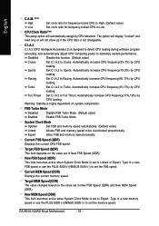
Manual User can manually input the correct settings Access Mode Use this to set the access mode for the hard drive. Extended IDE Drive SATA devices setup. You can ...
Manual User can manually input the correct settings Access Mode Use this to set the access mode for the hard drive. Extended IDE Drive SATA devices setup. You can ...
Manual
Page 54
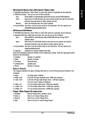
Automatically increase CPU frequency(7%,9%) by CPU loading. Full Thrust Set C.I .A.2 to Full Thrust. Enter FSB and memory speed manually. Target MEM Speed (DDR) The value changes based on the value set in a new FSB speed or use the PLUS SIGN (+)/MINUS ...QDR) This item becomes active when System Clock Mode is set to set the FSB speed. Current MEM Speed (DDR) Displays the current memory speed. GA-8N-SLI QUAD Royal Motherboard - 54 - The option will display "Locked" and read only or will automatically assign by CPU loading. Set C.I .A.2 to Turbo. Automatically increase...
Automatically increase CPU frequency(7%,9%) by CPU loading. Full Thrust Set C.I .A.2 to Full Thrust. Enter FSB and memory speed manually. Target MEM Speed (DDR) The value changes based on the value set in a new FSB speed or use the PLUS SIGN (+)/MINUS ...QDR) This item becomes active when System Clock Mode is set to set the FSB speed. Current MEM Speed (DDR) Displays the current memory speed. GA-8N-SLI QUAD Royal Motherboard - 54 - The option will display "Locked" and read only or will automatically assign by CPU loading. Set C.I .A.2 to Turbo. Automatically increase...

Manual
Page 81
...and press Del to identify the SATA controller for the SATA hard drive(s)/RAID array. If you may refer to the motherboard user's manual to enter BIOS Setup during OS installation. Appendix Then connect the power connector from your power supply to the hard drive. (2) ...the IDE/SATAII RAID Config item to create RAID array, press ENTER on the motherboard. English 4-1-4 Configuring SATA Hard Drive(s) (Controller: nVIDIA nForce4 SLI) To configure SATA hard drive(s), follow the steps below: (1) Install SATA hard drive(s) in your system. (2) Configure SATA controller mode and boot...
...and press Del to identify the SATA controller for the SATA hard drive(s)/RAID array. If you may refer to the motherboard user's manual to enter BIOS Setup during OS installation. Appendix Then connect the power connector from your power supply to the hard drive. (2) ...the IDE/SATAII RAID Config item to create RAID array, press ENTER on the motherboard. English 4-1-4 Configuring SATA Hard Drive(s) (Controller: nVIDIA nForce4 SLI) To configure SATA hard drive(s), follow the steps below: (1) Install SATA hard drive(s) in your system. (2) Configure SATA controller mode and boot...

Manual
Page 85
... through options. The size range is the standard unit of RAID 0 array creation. Appendix MediaShield IDE ROM BIOS 5.16 Copyright (C) 2005 NVIDIA Corp. You can manually set the striping block size. The KB is from 4K to enter the RAID BIOS setup utility. RAID Mode: Mirroring Striping Block: Optimal Free Disks...
... through options. The size range is the standard unit of RAID 0 array creation. Appendix MediaShield IDE ROM BIOS 5.16 Copyright (C) 2005 NVIDIA Corp. You can manually set the striping block size. The KB is from 4K to enter the RAID BIOS setup utility. RAID Mode: Mirroring Striping Block: Optimal Free Disks...
Manual
Page 90
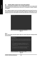
... your system to boot from a mass storage device manufacturer, or do not want to that you have chosen to manually specify an adapter. S=Specify Additional Device ENTER=Continue F3=Exit Figure 16 GA-8N-SLI QUAD Royal Motherboard - 90 - English (5) Installing SATA controller driver during OS installation Now that below appears (Figure 16), insert the floppy...
... your system to boot from a mass storage device manufacturer, or do not want to that you have chosen to manually specify an adapter. S=Specify Additional Device ENTER=Continue F3=Exit Figure 16 GA-8N-SLI QUAD Royal Motherboard - 90 - English (5) Installing SATA controller driver during OS installation Now that below appears (Figure 16), insert the floppy...
Manual
Page 100
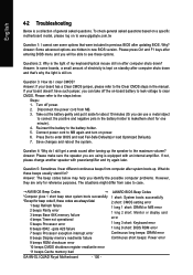
... the Clear CMOS steps in the battery holder to connect the positive and negative pins in the manual. Question 4: Why do I still get a weak sound after turning up . Answer: Please...beeps ROM checksum error 10 beeps CMOS shutdown register read/write error 11 beeps Cache memory bad GA-8N-SLI QUAD Royal Motherboard - 100 - Answer: If your board doesn't have such jumper, you can take...Take out the battery gently and put it aside for reference purposes. Connect power cord to www.gigabyte.com.tw Question 1: I hear different continuous beeps from MB. 3. Answer: The beep codes ...
... the Clear CMOS steps in the battery holder to connect the positive and negative pins in the manual. Question 4: Why do I still get a weak sound after turning up . Answer: Please...beeps ROM checksum error 10 beeps CMOS shutdown register read/write error 11 beeps Cache memory bad GA-8N-SLI QUAD Royal Motherboard - 100 - Answer: If your board doesn't have such jumper, you can take...Take out the battery gently and put it aside for reference purposes. Connect power cord to www.gigabyte.com.tw Question 1: I hear different continuous beeps from MB. 3. Answer: The beep codes ...


