Manual
Page 1
GA-8N-SLI QUAD Royal Intel® Pentium® Processor Extreme Edition Intel® Pentium® D / Pentium® 4 LGA775 Processor Motherboard User's Manual Rev. 1002 12ME-8NSLIQU-1002R * The WEEE marking on the product indicates this product must not be disposed of with user's other household waste and must be handed over to a designated collection point for the recycling of waste electrical and electronic equipment!! * The WEEE marking applies only in European Union's member states.
GA-8N-SLI QUAD Royal Intel® Pentium® Processor Extreme Edition Intel® Pentium® D / Pentium® 4 LGA775 Processor Motherboard User's Manual Rev. 1002 12ME-8NSLIQU-1002R * The WEEE marking on the product indicates this product must not be disposed of with user's other household waste and must be handed over to a designated collection point for the recycling of waste electrical and electronic equipment!! * The WEEE marking applies only in European Union's member states.

Manual
Page 2
Motherboard GA-8N-SLl QUAD Royal Nov. 16, 2005 Motherboard GA-8N-SLI QUAD Royal Nov. 16, 2005
Motherboard GA-8N-SLl QUAD Royal Nov. 16, 2005 Motherboard GA-8N-SLI QUAD Royal Nov. 16, 2005
Manual
Page 4
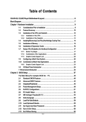
Table of Contents GA-8N-SLI QUAD Royal Motherboard Layout 6 Block Diagram ...7 Chapter 1 Hardware Installation 9 1-1 Considerations Prior to Installation 9 1-2 Feature Summary 10 1-3 Installation of the CPU and Heatsink 12...Removing Cool-Plus (Northbridge Cooling Fan 14 1-5 Installation of Memory 14 1-6 Installation of Expansion Cards 16 1-7 Setup of SLI (Scalable Link Interface) Configuration 17 1-7-1 Before You Begin 17 1-7-2 Combination of SLI Applications 20 1-7-3 Graphic Cards Support List 20 1-8 Configuring a Multi View System 22 1-8-1 Combination of Multi View Applications ...
Table of Contents GA-8N-SLI QUAD Royal Motherboard Layout 6 Block Diagram ...7 Chapter 1 Hardware Installation 9 1-1 Considerations Prior to Installation 9 1-2 Feature Summary 10 1-3 Installation of the CPU and Heatsink 12...Removing Cool-Plus (Northbridge Cooling Fan 14 1-5 Installation of Memory 14 1-6 Installation of Expansion Cards 16 1-7 Setup of SLI (Scalable Link Interface) Configuration 17 1-7-1 Before You Begin 17 1-7-2 Combination of SLI Applications 20 1-7-3 Graphic Cards Support List 20 1-8 Configuring a Multi View System 22 1-8-1 Combination of Multi View Applications ...
Manual
Page 6
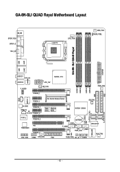
GA-8N-SLI QUAD Royal Motherboard Layout KB_MS SPDIF_RCA SPDIF_O 1394_6P LGA775 CPU_FAN MEN_FAN RUSB_PSEL GA-8N- SLI QUAD Royal ATXPWR LPT LAN2 LAN1 USB USB DDRII1 DDRII2 DDRII3 DDRII4 IDE1 IDE2 AUDIO1 ET1310 AUDIO2 ATX_12V F_AUDIO NB_FAN PCIEX8_1 NVIDIA C19 PWR_FAN CD_IN 88E1111 PCIEX1_1 SLI Switch Module Socket SB_FAN S_ATA0 S_ATA1 ALC850 SPDIF_IN IR IT8712 PCIEX16_1 PCIEX1_2 PCIEX16_2 Main Backup BIOS...
GA-8N-SLI QUAD Royal Motherboard Layout KB_MS SPDIF_RCA SPDIF_O 1394_6P LGA775 CPU_FAN MEN_FAN RUSB_PSEL GA-8N- SLI QUAD Royal ATXPWR LPT LAN2 LAN1 USB USB DDRII1 DDRII2 DDRII3 DDRII4 IDE1 IDE2 AUDIO1 ET1310 AUDIO2 ATX_12V F_AUDIO NB_FAN PCIEX8_1 NVIDIA C19 PWR_FAN CD_IN 88E1111 PCIEX1_1 SLI Switch Module Socket SB_FAN S_ATA0 S_ATA1 ALC850 SPDIF_IN IR IT8712 PCIEX16_1 PCIEX1_2 PCIEX16_2 Main Backup BIOS...
Manual
Page 10
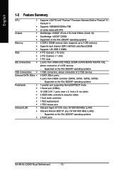
Supported on the Win 2000/XP operating systems 2 RJ45 ports GA-8N-SLI QUAD Royal Motherboard - 10 - Supported on the Win 2000/XP operating systems 1 parallel port supporting Normal/EPP/ECP mode 1 Serial port (COMA) 10 USB 2.0/1.1 ports (rear x 4, front x ...174; Pentium® Processor Extreme Edition/ Pentium® D / Pentium® 4 Supports 1066/800/533MHz FSB L2 cache varies with CPU Northbridge: nVIDIA® nForce 4 SLI Intel Edition (Crush 19) Southbridge: nVIDIA® CK804 Supported on the Win 2000/XP operating systems 1 FDD connection, allows connection of 4 IDE devices -
Supported on the Win 2000/XP operating systems 2 RJ45 ports GA-8N-SLI QUAD Royal Motherboard - 10 - Supported on the Win 2000/XP operating systems 1 parallel port supporting Normal/EPP/ECP mode 1 Serial port (COMA) 10 USB 2.0/1.1 ports (rear x 4, front x ...174; Pentium® Processor Extreme Edition/ Pentium® D / Pentium® 4 Supports 1066/800/533MHz FSB L2 cache varies with CPU Northbridge: nVIDIA® nForce 4 SLI Intel Edition (Crush 19) Southbridge: nVIDIA® CK804 Supported on the Win 2000/XP operating systems 1 FDD connection, allows connection of 4 IDE devices -
Manual
Page 12
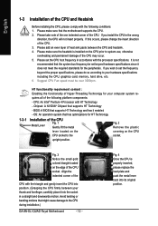
... lift the metal Fig. 2 Remove the plastic lever located on the CPU socket to the covering on the CPU prior to the CPU during installation.) GA-8N-SLI QUAD Royal Motherboard - 12 - BIOS: A BIOS that supports HT Technology - It is not recommended that has optimizations for your computer system re- Suggest CPU Fan speed must...
... lift the metal Fig. 2 Remove the plastic lever located on the CPU socket to the covering on the CPU prior to the CPU during installation.) GA-8N-SLI QUAD Royal Motherboard - 12 - BIOS: A BIOS that supports HT Technology - It is not recommended that has optimizations for your computer system re- Suggest CPU Fan speed must...
Manual
Page 14
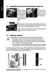
... into position. Fig.2 Once the fan is recommended that they can differ with the grooves in one side. Exerting too much pressure on one direction. GA-8N-SLI QUAD Royal Motherboard - 14 - Firmly press down until it snaps into the NB_FAN connector. Memory modules are unable to prevent hardware damage. 3. Fig.3 Before proceeding, first check...
... into position. Fig.2 Once the fan is recommended that they can differ with the grooves in one side. Exerting too much pressure on one direction. GA-8N-SLI QUAD Royal Motherboard - 14 - Firmly press down until it snaps into the NB_FAN connector. Memory modules are unable to prevent hardware damage. 3. Fig.3 Before proceeding, first check...
Manual
Page 15
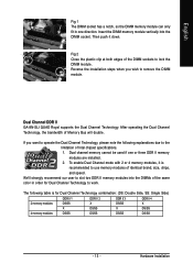
... chipset specifications. 1. We'll strongly recommend our user to slot two DDR II memory modules into the DIMM socket. Hardware Installation Dual Channel DDR II GA-8N-SLI QUAD Royal supports the Dual Channel Technology. The following explanations due to the limitation of the DIMM sockets to lock the DIMM module. English Fig.1 The DIMM...
... chipset specifications. 1. We'll strongly recommend our user to slot two DDR II memory modules into the DIMM socket. Hardware Installation Dual Channel DDR II GA-8N-SLI QUAD Royal supports the Dual Channel Technology. The following explanations due to the limitation of the DIMM sockets to lock the DIMM module. English Fig.1 The DIMM...

Manual
Page 16
... in the slot. 5. Replace the screw to install/ uninstall the VGA card. Make sure your VGA card is locked by following the steps outlined below: 1. GA-8N-SLI QUAD Royal Motherboard - 16 - Power on the slot. Press the expansion card firmly into the computer. 2. Install related driver from BIOS. 8. Be sure the metal contacts on...
... in the slot. 5. Replace the screw to install/ uninstall the VGA card. Make sure your VGA card is locked by following the steps outlined below: 1. GA-8N-SLI QUAD Royal Motherboard - 16 - Power on the slot. Press the expansion card firmly into the computer. 2. Install related driver from BIOS. 8. Be sure the metal contacts on...
Manual
Page 17
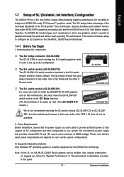
... that case, both of the PCIE x 16 slots will depend on your system. III. Note: As the SLI on GA-8N-SLI QUAD Royal supports various multiple video outputs combination, we suggest you use is able to provide sufficient power to install the GIGABYTE GV-3D1 graphics card on this guide. - 17 - Hardware Installation Together, the NVIDIA...
... that case, both of the PCIE x 16 slots will depend on your system. III. Note: As the SLI on GA-8N-SLI QUAD Royal supports various multiple video outputs combination, we suggest you use is able to provide sufficient power to install the GIGABYTE GV-3D1 graphics card on this guide. - 17 - Hardware Installation Together, the NVIDIA...
Manual
Page 18
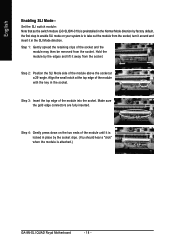
... angle. Step 1: Gently spread the retaining clips of the module until it away from the socket. Step 4: Gently press down on your system is attached.) GA-8N-SLI QUAD Royal Motherboard - 18 - Hold the module by factory default, the first step to take out the module from the socket, turn it around and insert it... in the Normal Mode direction by the edges and lift it is preinstalled in the SLI Mode direction. Set the SLI switch module: Note that as the switch module (GC-SLISW-C19) is locked in the socket. Step 3: Insert the top edge of the...
... angle. Step 1: Gently spread the retaining clips of the module until it away from the socket. Step 4: Gently press down on your system is attached.) GA-8N-SLI QUAD Royal Motherboard - 18 - Hold the module by factory default, the first step to take out the module from the socket, turn it around and insert it... in the Normal Mode direction by the edges and lift it is preinstalled in the SLI Mode direction. Set the SLI switch module: Note that as the switch module (GC-SLISW-C19) is locked in the socket. Step 3: Insert the top edge of the...
Manual
Page 20
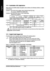
...enable the SLI function. GA-8N-SLI QUAD Royal Motherboard - 20 - English 1-7-2 Combination of SLI Applications Please make sure the BIOS settings and graphics cards conforms to the following conditions, to massive graphic cards on to page 55). North Bridge South Bridge NB SLI Switch VGA Driver Module SLI Enabled PCIEX8_1...Please refer to graphic card. Video output quantity is not used when more detail support lists please click onto Gigabyte's website at http://www.gigabyte.com.tw Figure 1-1. SLI Mode Video Remark Outputs(Note1) x16-x16 2 (NB+SB) x8-x8 2 (NB) x8-x8 ...
...enable the SLI function. GA-8N-SLI QUAD Royal Motherboard - 20 - English 1-7-2 Combination of SLI Applications Please make sure the BIOS settings and graphics cards conforms to the following conditions, to massive graphic cards on to page 55). North Bridge South Bridge NB SLI Switch VGA Driver Module SLI Enabled PCIEX8_1...Please refer to graphic card. Video output quantity is not used when more detail support lists please click onto Gigabyte's website at http://www.gigabyte.com.tw Figure 1-1. SLI Mode Video Remark Outputs(Note1) x16-x16 2 (NB+SB) x8-x8 2 (NB) x8-x8 ...

Manual
Page 22
... overall system configurations. GA-8N-SLI QUAD Royal Motherboard - 22 - Power requirement: The exact power requirement will depend on your system and the two graphics cards. NVIDIA video driver of the user by allowing them to spread multiple windows over eight monitors and view them simultaneously. With Multi View technology from GIGABYTE, Quad Graphic enabled motherboards offer...
... overall system configurations. GA-8N-SLI QUAD Royal Motherboard - 22 - Power requirement: The exact power requirement will depend on your system and the two graphics cards. NVIDIA video driver of the user by allowing them to spread multiple windows over eight monitors and view them simultaneously. With Multi View technology from GIGABYTE, Quad Graphic enabled motherboards offer...

Manual
Page 24
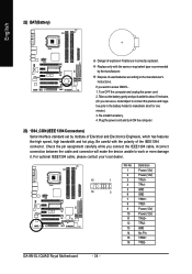
.... LAN Port 1 The provided Internet connection is Gigabit Ethernet, providing data transfer speeds of 10/100/ 1000Mbps. Line In Devices like CD-ROM, walkman etc. GA-8N-SLI QUAD Royal Motherboard - 24 - LAN Port 2 The provided Internet connection is Gigabit Ethernet (PCI Express Gigabit), providing data transfer speeds of providing digital audio to external speakers...
.... LAN Port 1 The provided Internet connection is Gigabit Ethernet, providing data transfer speeds of 10/100/ 1000Mbps. Line In Devices like CD-ROM, walkman etc. GA-8N-SLI QUAD Royal Motherboard - 24 - LAN Port 2 The provided Internet connection is Gigabit Ethernet (PCI Express Gigabit), providing data transfer speeds of providing digital audio to external speakers...
Manual
Page 26
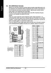
... 14 -12V 15 GND 16 PS_ON(soft On/Off) 17 GND 18 GND 19 GND 20 -5V 21 +5V 22 +5V 23 +5V 24 GND GA-8N-SLI QUAD Royal Motherboard - 26 - If the ATX_12V power connector is unable to start . Align the power connector with its proper location on the motherboard before plugging in...
... 14 -12V 15 GND 16 PS_ON(soft On/Off) 17 GND 18 GND 19 GND 20 -5V 21 +5V 22 +5V 23 +5V 24 GND GA-8N-SLI QUAD Royal Motherboard - 26 - If the ATX_12V power connector is unable to start . Align the power connector with its proper location on the motherboard before plugging in...
Manual
Page 28
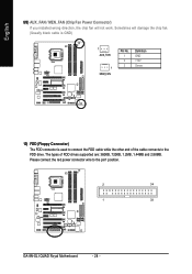
Sometimes will not work. The types of the cable connects to the FDD drive. English 8/9) AUX_FAN / MEN_FAN (Chip Fan Power Connector) If you installed wrong direction, the chip fan will damage the chip fan. (Usually black cable is GND) 1 AUX_FAN 1 MEM_FAN Pin No. 1 2 3 Definition GND +12V Sense 10) FDD (Floppy Connector) The FDD connector is used to connect the FDD cable while the other end of FDD drives supported are: 360KB, 720KB, 1.2MB, 1.44MB and 2.88MB. Please connect the red power connector wire to the pin1 position. 2 34 1 33 GA-8N-SLI QUAD Royal Motherboard - 28 -
Sometimes will not work. The types of the cable connects to the FDD drive. English 8/9) AUX_FAN / MEN_FAN (Chip Fan Power Connector) If you installed wrong direction, the chip fan will damage the chip fan. (Usually black cable is GND) 1 AUX_FAN 1 MEM_FAN Pin No. 1 2 3 Definition GND +12V Sense 10) FDD (Floppy Connector) The FDD connector is used to connect the FDD cable while the other end of FDD drives supported are: 360KB, 720KB, 1.2MB, 1.44MB and 2.88MB. Please connect the red power connector wire to the pin1 position. 2 34 1 33 GA-8N-SLI QUAD Royal Motherboard - 28 -
Manual
Page 30
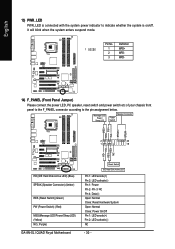
... Disk Active LED) (Blue) SPEAK (Speaker Connector) (Amber) RES (Reset Switch) (Green) PW (Power Switch) (Red) MSG(Message LED/Power/Sleep LED) (Yellow) NC ( Purple) GA-8N-SLI QUAD Royal Motherboard Reset Switch IDE Hard Disk Active LED Pin 1: LED anode(+) Pin 2: LED cathode(-) Pin 1: Power Pin 2-
... Disk Active LED) (Blue) SPEAK (Speaker Connector) (Amber) RES (Reset Switch) (Green) PW (Power Switch) (Red) MSG(Message LED/Power/Sleep LED) (Yellow) NC ( Purple) GA-8N-SLI QUAD Royal Motherboard Reset Switch IDE Hard Disk Active LED Pin 1: LED anode(+) Pin 2: LED cathode(-) Pin 1: Power Pin 2-
Manual
Page 32
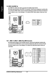
... of the front USB connector. Definition 1 Power(5V) 2 10 2 Power(5V) 3 USB DX- 4 USB Dy- 5 USB DX+ 1 9 6 USB Dy+ 7 GND 8 GND 9 No Pin 10 NC GA-8N-SLI QUAD Royal Motherboard - 32 - Pin No. Check the pin assignment carefully while you connect the front USB cable, incorrect connection between the cable and connector will make...
... of the front USB connector. Definition 1 Power(5V) 2 10 2 Power(5V) 3 USB DX- 4 USB Dy- 5 USB DX+ 1 9 6 USB Dy+ 7 GND 8 GND 9 No Pin 10 NC GA-8N-SLI QUAD Royal Motherboard - 32 - Pin No. Check the pin assignment carefully while you connect the front USB cable, incorrect connection between the cable and connector will make...
Manual
Page 34
... it aside for about 10 minutes. (Or you want to the manufacturer's instructions. Replace only with the polarity of used batteries according to erase CMOS... 1. GA-8N-SLI QUAD Royal Motherboard - 34 -
... it aside for about 10 minutes. (Or you want to the manufacturer's instructions. Replace only with the polarity of used batteries according to erase CMOS... 1. GA-8N-SLI QUAD Royal Motherboard - 34 -
Manual
Page 36
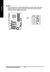
Definition 1 Power 1 2 RFID_RI- 3 RF_TXD 4 RF_RXD 5 NC 6 GND GA-8N-SLI QUAD Royal Motherboard - 36 - Pin No. Check the pin assignments before you to connect external devices to use extra function. English 26) RF_ID This connector allows you connect the external device cable. Please contact your nearest dealer for the optional GIGABYTE external device.
Definition 1 Power 1 2 RFID_RI- 3 RF_TXD 4 RF_RXD 5 NC 6 GND GA-8N-SLI QUAD Royal Motherboard - 36 - Pin No. Check the pin assignments before you to connect external devices to use extra function. English 26) RF_ID This connector allows you connect the external device cable. Please contact your nearest dealer for the optional GIGABYTE external device.


