
User Manual
Page 1
Note : Although Gigabyte's AG32S(G) graphics card is based on ATi Rage 128 Pro chip, the design of AG32S(G) is compliance with 2X(3.3V)/4X(1....install this card is 2X(3.3V). Please insert an AGP 4X/8X card. Example 2: Some ATi Rage 128 Pro graphics cards made by "Power Color", the graphics card manufacturer & some SiS 305 cards, their golden finger ... 845(GE/PE) / 845(E/G) / 850(E) / E7205 / 865(G/PE/P) / 875P based motherboards. The GA-8IPE1000 Series (or any AGP 4X/8X only) motherboards might not function properly, If you install PCI cards, please remove the Dual BIOS label from PCI...
Note : Although Gigabyte's AG32S(G) graphics card is based on ATi Rage 128 Pro chip, the design of AG32S(G) is compliance with 2X(3.3V)/4X(1....install this card is 2X(3.3V). Please insert an AGP 4X/8X card. Example 2: Some ATi Rage 128 Pro graphics cards made by "Power Color", the graphics card manufacturer & some SiS 305 cards, their golden finger ... 845(GE/PE) / 845(E/G) / 850(E) / E7205 / 865(G/PE/P) / 875P based motherboards. The GA-8IPE1000 Series (or any AGP 4X/8X only) motherboards might not function properly, If you install PCI cards, please remove the Dual BIOS label from PCI...

User Manual
Page 2
M Please do not remove any errors or omissions that may void the warranty of this booklet. M Due to rapid change in this motherboard. M The author assumes no responsibility for any labels on motherboard, this may appear in technology, some of the specifications might be out of date before publication of this document nor does the author make a commitment to update the information contained herein. M Third-party brands and names are the property of their respective owners.
M Please do not remove any errors or omissions that may void the warranty of this booklet. M Due to rapid change in this motherboard. M The author assumes no responsibility for any labels on motherboard, this may appear in technology, some of the specifications might be out of date before publication of this document nor does the author make a commitment to update the information contained herein. M Third-party brands and names are the property of their respective owners.

User Manual
Page 4
...-9338/ (818) 854-9339 hereby declares that may not cause harmful and (2) this device must accept any inference received, including that the product Product Name: Motherboard Model Number: GA-8IPE1000 Pro-G/GA-8IPE1000-G/ GA-8IPE1000 Conforms to the following two conditions: (1) This device may cause undesired operation. DECLARATION OF CONFORMITY Per FCC Part 2 Section 2.1077(a) Responsible Party Name:G.B.T.
...-9338/ (818) 854-9339 hereby declares that may not cause harmful and (2) this device must accept any inference received, including that the product Product Name: Motherboard Model Number: GA-8IPE1000 Pro-G/GA-8IPE1000-G/ GA-8IPE1000 Conforms to the following two conditions: (1) This device may cause undesired operation. DECLARATION OF CONFORMITY Per FCC Part 2 Section 2.1077(a) Responsible Party Name:G.B.T.

User Manual
Page 5
GA-8IPE1000 Series P4 Titan Series Motherboard USER'S MANUAL Pentium®4 Processor Motherboard Rev. 3001 12ME-8IPE1KG-3001
GA-8IPE1000 Series P4 Titan Series Motherboard USER'S MANUAL Pentium®4 Processor Motherboard Rev. 3001 12ME-8IPE1KG-3001

User Manual
Page 6
English Table of Content Warning 4 Chapter 1 Introduction 5 Features Summary 5 GA-8IPE1000 Series Motherboard Layout 8 Block Diagram 9 Chapter 2 Hardware Installation Process 11 Step 1: Install the Central Processing Unit (CPU 12 Step 1-1: CPU Installation 12 Step 1-2 ... I/O Back Panel Introduction 18 Step 4-2: Connectors & Jumper Setting Introduction 20 Chapter 3 BIOS Setup 35 The Main Menu (For example: BIOS Ver.: 8IPE1000 Pro-G.E1 36 Standard CMOS Features 38 Advanced BIOS Features 41 Integrated Peripherals 43 Power Management Setup 48 GA-8IPE1000 Series Motherboard - 2 -
English Table of Content Warning 4 Chapter 1 Introduction 5 Features Summary 5 GA-8IPE1000 Series Motherboard Layout 8 Block Diagram 9 Chapter 2 Hardware Installation Process 11 Step 1: Install the Central Processing Unit (CPU 12 Step 1-1: CPU Installation 12 Step 1-2 ... I/O Back Panel Introduction 18 Step 4-2: Connectors & Jumper Setting Introduction 20 Chapter 3 BIOS Setup 35 The Main Menu (For example: BIOS Ver.: 8IPE1000 Pro-G.E1 36 Standard CMOS Features 38 Advanced BIOS Features 41 Integrated Peripherals 43 Power Management Setup 48 GA-8IPE1000 Series Motherboard - 2 -

User Manual
Page 8
...). Hold components by the hole. Justcut the bottom portion ofthe spacers (the spacer may damage the board or cause board malfunctioning. GA-8IPE1000 Series Motherboard - 4 - To protect them againstdamage from the system. 5. Use a grounded wrist strap before handling computer components.Ifyou do not...one, touch both of your computer. 1. Unplug yourcomputer when working on the bag thatcame with the holes on the motherboard. If the motherboard has mounting holes, but they don't line up with the components whenever the components are separated from static electricity, you...
...). Hold components by the hole. Justcut the bottom portion ofthe spacers (the spacer may damage the board or cause board malfunctioning. GA-8IPE1000 Series Motherboard - 4 - To protect them againstdamage from the system. 5. Use a grounded wrist strap before handling computer components.Ifyou do not...one, touch both of your computer. 1. Unplug yourcomputer when working on the bag thatcame with the holes on the motherboard. If the motherboard has mounting holes, but they don't line up with the components whenever the components are separated from static electricity, you...

User Manual
Page 9
.../ATA100) IDE & ATAPI CD-ROM - 2 SerialATA connectors (SATA0/SATA1) in 150 MB/s operation mode - Introduction English Chapter 1 Introduction Features Summary Form Factor Motherboard CPU Chip set Memory I /O Controller Hub - 4 184-pin DDR DIMM sockets - Support Intel® Pentium® 4 (Northwood, Prescott) processor - ICH5... FC-PGA2 Pentium® 4 processor - A FSB 400 Pentium 4 processor will support DDR333 and DDR266 memory module. GA-8IPE1000 Series Motherboard: GA-8IPE1000 Pro-G/GA-8IPE1000-G/GA-8IPE1000 - Socket 478 for up to be continued...... Due to 4 ATAPI devices -
.../ATA100) IDE & ATAPI CD-ROM - 2 SerialATA connectors (SATA0/SATA1) in 150 MB/s operation mode - Introduction English Chapter 1 Introduction Features Summary Form Factor Motherboard CPU Chip set Memory I /O Controller Hub - 4 184-pin DDR DIMM sockets - Support Intel® Pentium® 4 (Northwood, Prescott) processor - ICH5... FC-PGA2 Pentium® 4 processor - A FSB 400 Pentium 4 processor will support DDR333 and DDR266 memory module. GA-8IPE1000 Series Motherboard: GA-8IPE1000 Pro-G/GA-8IPE1000-G/GA-8IPE1000 - Socket 478 for up to be continued...... Due to 4 ATAPI devices -

User Manual
Page 10
... Connector - 3 IEEE1394 (by s/w switch) - CPU/Power (*)/System Fan Fail Warning - Line In / 2 rear speaker(by cable) (*) - 1 IrDA connector for IR/CIR - GA-8IPE1000 Series Motherboard - 6 - CPU Overheat Warning - SPDIF Out /SPDIF In - Ti TSB43AB23 - Supports Multi Language (*) - Surround Back speaker (by s/w switch) - CD_In / Game Connector - SupportJack... a r d L A N ( u) * O n - Build in Marvell 8001 Chipset (10/100/1000 Mbit)(*u) - 1 RJ45 port - Supports Face Wizard (*) to be continued...... (*) For GA-8IPE1000 Pro-G only. (u) For GA-8IPE1000-G only.
... Connector - 3 IEEE1394 (by s/w switch) - CPU/Power (*)/System Fan Fail Warning - Line In / 2 rear speaker(by cable) (*) - 1 IrDA connector for IR/CIR - GA-8IPE1000 Series Motherboard - 6 - CPU Overheat Warning - SPDIF Out /SPDIF In - Ti TSB43AB23 - Supports Multi Language (*) - Surround Back speaker (by s/w switch) - CD_In / Game Connector - SupportJack... a r d L A N ( u) * O n - Build in Marvell 8001 Chipset (10/100/1000 Mbit)(*u) - 1 RJ45 port - Supports Face Wizard (*) to be continued...... (*) For GA-8IPE1000 Pro-G only. (u) For GA-8IPE1000-G only.

User Manual
Page 12
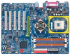
Note: If the NorthBridge on the motherboard has a fan sink, then the motherboard contains a NB_FAN connector. GA-8IPE1000 Series Motherboard - 8 - English GA-8IPE1000 Series Motherboard Layout COMA KB_MS R_U SB ATX_12V SOC KET478 Hyper Threading CPU_FAN ATX FDD IDE1 DDR1 GA-8IPE1000 (Pro)(-G) COMB LPT (*u) N A L MIC_IN USB LINE_OUT LINE_IN CD_IN DDR2 DDR3 DDR4 IDE2 F_AU DIO Marv ... ( ) PCI5 F2_1394 (* ) ICH 5 SATA 1 SATA 0 C LR_C M OS SYS_FAN IN FO_LIN K F_PAN EL F1_1394 (* ) F_U SB2 F_U SB1 PWR_LED (*) For GA-8IPE1000 Pro-G only. (u) For GA-8IPE1000-G only.
Note: If the NorthBridge on the motherboard has a fan sink, then the motherboard contains a NB_FAN connector. GA-8IPE1000 Series Motherboard - 8 - English GA-8IPE1000 Series Motherboard Layout COMA KB_MS R_U SB ATX_12V SOC KET478 Hyper Threading CPU_FAN ATX FDD IDE1 DDR1 GA-8IPE1000 (Pro)(-G) COMB LPT (*u) N A L MIC_IN USB LINE_OUT LINE_IN CD_IN DDR2 DDR3 DDR4 IDE2 F_AU DIO Marv ... ( ) PCI5 F2_1394 (* ) ICH 5 SATA 1 SATA 0 C LR_C M OS SYS_FAN IN FO_LIN K F_PAN EL F1_1394 (* ) F_U SB2 F_U SB1 PWR_LED (*) For GA-8IPE1000 Pro-G only. (u) For GA-8IPE1000-G only.

User Manual
Page 14
English GA-8IPE1000 Series Motherboard - 10 -
English GA-8IPE1000 Series Motherboard - 10 -

User Manual
Page 15
Install memory modules Step 3- Turn on the motherboard has a fan sink, then the motherboard contains a NB_FAN connector. - 11 - Install expansion cards Step 4- Continue with the BIOS/software installation. Hardware Installation Process Install the Central Processing Unit (CPU) Step 2- Connect ...
Install memory modules Step 3- Turn on the motherboard has a fan sink, then the motherboard contains a NB_FAN connector. - 11 - Install expansion cards Step 4- Continue with the BIOS/software installation. Hardware Installation Process Install the Central Processing Unit (CPU) Step 2- Connect ...

User Manual
Page 16
Please make sure the CPU type is supported by the motherboard. Angling the rod to 65-degree maybe feel a kind of tight, and then continue pull the rod to 650 Socket Actuation Lever 1. Pin1 indicator Pin1 ... to the following warning: If you do not match the CPU socket Pin 1 and CPU cut edge on the CPU upper corner. CPU Top View GA-8IPE1000 Series Motherboard 4. Then insert the CPU into the socket. - 12 - English Step 1: Install the Central Processing Unit (CPU) Before installing the processor,adhere to the 90...
Please make sure the CPU type is supported by the motherboard. Angling the rod to 65-degree maybe feel a kind of tight, and then continue pull the rod to 650 Socket Actuation Lever 1. Pin1 indicator Pin1 ... to the following warning: If you do not match the CPU socket Pin 1 and CPU cut edge on the CPU upper corner. CPU Top View GA-8IPE1000 Series Motherboard 4. Then insert the CPU into the socket. - 12 - English Step 1: Install the Central Processing Unit (CPU) Before installing the processor,adhere to the 90...

User Manual
Page 18
... only fit in one DDR memory module is installed: The Dual Channel Technology can vary between sockets. Notch DDR GA-8IPE1000 Series supports the Dual Channel Technology. Wrong orientation will cause improper installation. GA-8IPE1000 Series Motherboard - 14 - English Step 2: Install memory modules Before installing the processor and heatsink, adhere to the following explanations due...
... only fit in one DDR memory module is installed: The Dual Channel Technology can vary between sockets. Notch DDR GA-8IPE1000 Series supports the Dual Channel Technology. Wrong orientation will cause improper installation. GA-8IPE1000 Series Motherboard - 14 - English Step 2: Install memory modules Before installing the processor and heatsink, adhere to the following explanations due...

User Manual
Page 20
... is the best choice for build ing high performance and low latency DRAM subsystem that are suitable for memory ven dors, OEMs, and system integrators. GA-8IPE1000 Series Motherboard - 16 - Then push it down. 3. Nowadays, with the highestbandwidth of 3.2GB/ s of DDR400 memory and complete line of the DIMM slots to remove the...
... is the best choice for build ing high performance and low latency DRAM subsystem that are suitable for memory ven dors, OEMs, and system integrators. GA-8IPE1000 Series Motherboard - 16 - Then push it down. 3. Nowadays, with the highestbandwidth of 3.2GB/ s of DDR400 memory and complete line of the DIMM slots to remove the...

User Manual
Page 21
Read the related expansion card's instruction documentbefore install the expansion card into expansion slotin motherboard. 4. Be sure the metalcontacts on the slot .Make sure yourAGP card is locked by the small whitedrawable bar. - 17 - Install related driver from the computer. 3. ...
Read the related expansion card's instruction documentbefore install the expansion card into expansion slotin motherboard. 4. Be sure the metalcontacts on the slot .Make sure yourAGP card is locked by the small whitedrawable bar. - 17 - Install related driver from the computer. 3. ...

User Manual
Page 22
.../100/ 1000 Mbps speed. (*) For GA-8IPE1000 Pro-G only. (u) For GA-8IPE1000-G only. Also make sure you connect your device(s) into USB connector(s), plea se make sure your device(s) such as USB keyboard,mouse, scanner, zip, speaker..etc. Have a standard USB interfa ce. If your OS or device(s) vendors. GA-8IPE1000 Series Motherboard - 18 - F or more information please...
.../100/ 1000 Mbps speed. (*) For GA-8IPE1000 Pro-G only. (u) For GA-8IPE1000-G only. Also make sure you connect your device(s) into USB connector(s), plea se make sure your device(s) such as USB keyboard,mouse, scanner, zip, speaker..etc. Have a standard USB interfa ce. If your OS or device(s) vendors. GA-8IPE1000 Series Motherboard - 18 - F or more information please...

User Manual
Page 24
GA-8IPE1000 Series Motherboard - 20 - Note: If the NorthBridge on the motherboard has a fan sink, then the motherboard contains a NB_FAN connector. English Step 4-2: Connectors & Jumper Setting Introduction 1 3 6(*) 12 14 13 23 16 18 1) ATX_12V 2) ATX 3) CPU_FAN 4) SYS_FAN 5) P W R _ F A N (*) 6) N B _ F A N (*) 7) IDE1/IDE2 8) FDD 9) PWR_LED 10) BAT ... 13) SUR_CEN 14) CD_IN 15) SPDIF_IO 16) IR_CIR 17) F_USB1/F_USB2 18) GAME 19) INFO_LINK 20) F 2 _ 1 3 9 4 (*) 21) F 1 _ 1 3 9 4 (*) 22) SATA0/SATA1 23) CI 24) CLR_CMOS (*) For GA-8IPE1000 Pro-G only.
GA-8IPE1000 Series Motherboard - 20 - Note: If the NorthBridge on the motherboard has a fan sink, then the motherboard contains a NB_FAN connector. English Step 4-2: Connectors & Jumper Setting Introduction 1 3 6(*) 12 14 13 23 16 18 1) ATX_12V 2) ATX 3) CPU_FAN 4) SYS_FAN 5) P W R _ F A N (*) 6) N B _ F A N (*) 7) IDE1/IDE2 8) FDD 9) PWR_LED 10) BAT ... 13) SUR_CEN 14) CD_IN 15) SPDIF_IO 16) IR_CIR 17) F_USB1/F_USB2 18) GAME 19) INFO_LINK 20) F 2 _ 1 3 9 4 (*) 21) F 1 _ 1 3 9 4 (*) 22) SATA0/SATA1 23) CI 24) CLR_CMOS (*) For GA-8IPE1000 Pro-G only.

User Manual
Page 26
current up to lower the system temperature. Definition 1 GND 1 2 +12V 3 Sense 4) SYS_FAN (System FAN Connector) This connector allows you to link with the cooling fan on the system case to 600 mA. PinNo. PinNo. Definition 1 GND 1 2 +12V 3 Sense GA-8IPE1000 Series Motherboard - 22 - English 3) CPU_FAN (CPU FAN Connector) Please note, a proper installation of the CPU cooler is essential to prevent the CPU from running under abnormal condition or damaged by overheating.The CPU fan connector supports Max.
current up to lower the system temperature. Definition 1 GND 1 2 +12V 3 Sense 4) SYS_FAN (System FAN Connector) This connector allows you to link with the cooling fan on the system case to 600 mA. PinNo. PinNo. Definition 1 GND 1 2 +12V 3 Sense GA-8IPE1000 Series Motherboard - 22 - English 3) CPU_FAN (CPU FAN Connector) Please note, a proper installation of the CPU cooler is essential to prevent the CPU from running under abnormal condition or damaged by overheating.The CPU fan connector supports Max.

User Manual
Page 27
... GA-8IPE1000 Pro-G only. - 23 - Hardware Installation Process Sometimes will not work. PinNo. PinNo. English 5) * P W R _ F A N ( P o w e r F a n C o n n e c t o r ) ( ) This connector allows you installed wrong direction, the Chip Fan will damage the Chip Fan. (Usually black cable is GND) Note: If the NorthBridge on the system case to link with the cooling fan on the motherboard... has a fan sink, then the motherboard contains a NB_FAN connector.
... GA-8IPE1000 Pro-G only. - 23 - Hardware Installation Process Sometimes will not work. PinNo. PinNo. English 5) * P W R _ F A N ( P o w e r F a n C o n n e c t o r ) ( ) This connector allows you installed wrong direction, the Chip Fan will damage the Chip Fan. (Usually black cable is GND) Note: If the NorthBridge on the system case to link with the cooling fan on the motherboard... has a fan sink, then the motherboard contains a NB_FAN connector.

User Manual
Page 28
English IDE2 IDE1 7) IDE1/ IDE2(IDE1/IDE2 Connector) Please connect first harddisk to IDE1 and connectCDROM to FDD. Itsupports 360K,720K,1.2M,1.44M and 2.88Mbytes floppy disk types. The red stripe of the ribbon cable must be the same side with the Pin1. 40 39 2 1 8) FDD (Floppy Connector) Please connect the floppy drive ribbon cables to IDE2. The red stripe of the ribbon cable must be the same side with the Pin1. 34 33 2 1 GA-8IPE1000 Series Motherboard - 24 -
English IDE2 IDE1 7) IDE1/ IDE2(IDE1/IDE2 Connector) Please connect first harddisk to IDE1 and connectCDROM to FDD. Itsupports 360K,720K,1.2M,1.44M and 2.88Mbytes floppy disk types. The red stripe of the ribbon cable must be the same side with the Pin1. 40 39 2 1 8) FDD (Floppy Connector) Please connect the floppy drive ribbon cables to IDE2. The red stripe of the ribbon cable must be the same side with the Pin1. 34 33 2 1 GA-8IPE1000 Series Motherboard - 24 -


