Manual
Page 1
GA-8I945P Pro/ GA-8I945P-G Intel® Pentium® D / Pentium® 4 LGA775 Processor Motherboard User's Manual Rev. 1005 12ME-8I945PP-1005 * The WEEE marking on the product indicates this product must not be disposed of with user's other household waste and must be handed over to a designated collection point for the recycling of waste electrical and electronic equipment!! * The WEEE marking applies only in European Union's member states.
GA-8I945P Pro/ GA-8I945P-G Intel® Pentium® D / Pentium® 4 LGA775 Processor Motherboard User's Manual Rev. 1005 12ME-8I945PP-1005 * The WEEE marking on the product indicates this product must not be disposed of with user's other household waste and must be handed over to a designated collection point for the recycling of waste electrical and electronic equipment!! * The WEEE marking applies only in European Union's member states.
Manual
Page 2
Motherboard GA-8I945P Pro/GA-8I945P-G Apr. 18, 2005 Motherboard GA-8I945P Pro/GA-8I945P-G Apr. 18, 2005
Motherboard GA-8I945P Pro/GA-8I945P-G Apr. 18, 2005 Motherboard GA-8I945P Pro/GA-8I945P-G Apr. 18, 2005
Manual
Page 4
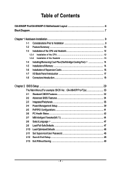
Table of Contents GA-8I945P Pro/GA-8I945P-G Motherboard Layout 6 Block Diagram ...7 Chapter 1 Hardware Installation 9 1-1 Considerations Prior to Installation 9 1-2 Feature Summary 10 1-3 Installation of the CPU and Heatsink 12 1-3-1... of Expansion Cards 16 1-7 I/O Back Panel Introduction 17 1-8 Connectors Introduction 18 Chapter 2 BIOS Setup 29 The Main Menu (For example: BIOS Ver. : GA-8I945P Pro F2a 30 2-1 Standard CMOS Features 32 2-2 Advanced BIOS Features 34 2-3 IntegratedPeripherals 36 2-4 Power Management Setup 39 2-5 PnP/PCI Configurations 41 2-6 PC Health Status...
Table of Contents GA-8I945P Pro/GA-8I945P-G Motherboard Layout 6 Block Diagram ...7 Chapter 1 Hardware Installation 9 1-1 Considerations Prior to Installation 9 1-2 Feature Summary 10 1-3 Installation of the CPU and Heatsink 12 1-3-1... of Expansion Cards 16 1-7 I/O Back Panel Introduction 17 1-8 Connectors Introduction 18 Chapter 2 BIOS Setup 29 The Main Menu (For example: BIOS Ver. : GA-8I945P Pro F2a 30 2-1 Standard CMOS Features 32 2-2 Advanced BIOS Features 34 2-3 IntegratedPeripherals 36 2-4 Power Management Setup 39 2-5 PnP/PCI Configurations 41 2-6 PC Health Status...
Manual
Page 7
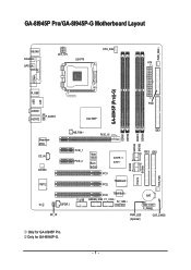
Only for GA-8I945P Pro. GA-8I945P Pro/GA-8I945P-G Motherboard Layout KB_MS ATX_12V CPU_FAN COAXIAL LGA775 ATX OPTICAL PWR_FAN LPT LAN COMA GA-8I945P (Pro)(-G) R_USB USB FDD AUDIO1 AUDIO2 F_AUDIO Intel 945P Broadcom 5789 CD_IN CODEC IT8712 NB_FAN PCIE_16 PCIE_1 PCIE_2 Main BIOS Back BIOS ICH7R / ICH7 PCI1 TSB82AA2 PCI2 SATAII0 IT8212 SATAII1 DDRII1 DDRII2 SATAII2 SATAII3 DDRII3 DDRII4 IDE1 IDE3 IDE2 SYS_FAN PCI3 TSB81BA3 BAT F_USB GREEN_USB F1_1394 F2_1394 CI SPDIF_I F_PANEL RF_ID PWR_LED (Optional) CLR_CMOS Only for GA-8I945P-G. - 7 -
Only for GA-8I945P Pro. GA-8I945P Pro/GA-8I945P-G Motherboard Layout KB_MS ATX_12V CPU_FAN COAXIAL LGA775 ATX OPTICAL PWR_FAN LPT LAN COMA GA-8I945P (Pro)(-G) R_USB USB FDD AUDIO1 AUDIO2 F_AUDIO Intel 945P Broadcom 5789 CD_IN CODEC IT8712 NB_FAN PCIE_16 PCIE_1 PCIE_2 Main BIOS Back BIOS ICH7R / ICH7 PCI1 TSB82AA2 PCI2 SATAII0 IT8212 SATAII1 DDRII1 DDRII2 SATAII2 SATAII3 DDRII3 DDRII4 IDE1 IDE3 IDE2 SYS_FAN PCI3 TSB81BA3 BAT F_USB GREEN_USB F1_1394 F2_1394 CI SPDIF_I F_PANEL RF_ID PWR_LED (Optional) CLR_CMOS Only for GA-8I945P-G. - 7 -
Manual
Page 8
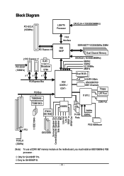
Only for GA-8I945P-G. - 8 - Block Diagram PCI-ECLK (100MHz) LGA775 Processor CPUCLK+/-(133/200/266MHz) PCI Express x16 2 PCI Express x1 RJ45 PCI-ECLK (100MHz) Broadcom 5789 x1 x1 x 1 ... Speaker Out Side Speaker Out MIC Line-Out Line-In SPDIF In SPDIF Out PCICLK (33MHz) (Note) To use a DDRII 667 memory module on the motherboard, you must install an 800/1066MHz FSB processor . Only for GA-8I945P Pro.
Only for GA-8I945P-G. - 8 - Block Diagram PCI-ECLK (100MHz) LGA775 Processor CPUCLK+/-(133/200/266MHz) PCI Express x16 2 PCI Express x1 RJ45 PCI-ECLK (100MHz) Broadcom 5789 x1 x1 x 1 ... Speaker Out Side Speaker Out MIC Line-Out Line-In SPDIF In SPDIF Out PCICLK (33MHz) (Note) To use a DDRII 667 memory module on the motherboard, you must install an 800/1066MHz FSB processor . Only for GA-8I945P Pro.
Manual
Page 10
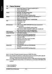
... chip (10/100/1000 Mbit) 1 RJ 45 port Supported on the Win 2000/XP operating systems (Note 1) For further CPU support information, please go to GIGABYTE's website. (Note 2) Due to 4GB memory) (Note 2) Supports 1.8V DDR II DIMM Supports dual channel DDR II 667(Note 3)/533/400 DIMM 1 PCI.../ATA 66/ATA 100), allows connection of memory is reserved for system usage and therefore the actual memory size is less than the stated amount. GA-8I945P (Pro)(-G) Motherboard - 10 - Supported on the Win 2000/XP operating systems 2 IDE connection (UDMA 33/ATA 66/ATA 100/ATA 133), compatible with CPU ...
... chip (10/100/1000 Mbit) 1 RJ 45 port Supported on the Win 2000/XP operating systems (Note 1) For further CPU support information, please go to GIGABYTE's website. (Note 2) Due to 4GB memory) (Note 2) Supports 1.8V DDR II DIMM Supports dual channel DDR II 667(Note 3)/533/400 DIMM 1 PCI.../ATA 66/ATA 100), allows connection of memory is reserved for system usage and therefore the actual memory size is less than the stated amount. GA-8I945P (Pro)(-G) Motherboard - 10 - Supported on the Win 2000/XP operating systems 2 IDE connection (UDMA 33/ATA 66/ATA 100/ATA 133), compatible with CPU ...
Manual
Page 12
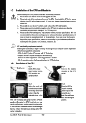
...Please make sure that supports HT Technology and has it does not meet the required standards for the peripherals. BIOS: A BIOS that the motherboard supports the CPU. 2. If you install the CPU in the wrong direction, the CPU will not insert properly. Fig. 4 Once the...use, otherwise overheating and permanent damage of the CPU may occur. 5. It is installed on the CPU socket to the CPU during installation.) GA-8I945P (Pro)(-G) Motherboard - 12 - Chipset: An Intel® Chipset that might cause damage to the upright position. Fig. 2 Remove the plastic covering on ...
...Please make sure that supports HT Technology and has it does not meet the required standards for the peripherals. BIOS: A BIOS that the motherboard supports the CPU. 2. If you install the CPU in the wrong direction, the CPU will not insert properly. Fig. 4 Once the...use, otherwise overheating and permanent damage of the CPU may occur. 5. It is installed on the CPU socket to the CPU during installation.) GA-8I945P (Pro)(-G) Motherboard - 12 - Chipset: An Intel® Chipset that might cause damage to the upright position. Fig. 2 Remove the plastic covering on ...
Manual
Page 14
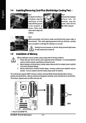
...each slot. A memory module can be inserted only in one direction. Memory modules are unable to insert the module, please switch the direction. GA-8I945P (Pro)(-G) Motherboard - 14 - Notch DDR II Fig.3 Before proceeding, first check to make sure that they can be used. 2. Before installing or removing ... modules, please make sure that memory of similar capacity, specifications and brand be installed in the heatsink as shown. Only for GA-8I945P Pro. Firmly press down until it snaps into the NB_FAN connector. Exerting too much pressure on the fan during removal might cause the...
...each slot. A memory module can be inserted only in one direction. Memory modules are unable to insert the module, please switch the direction. GA-8I945P (Pro)(-G) Motherboard - 14 - Notch DDR II Fig.3 Before proceeding, first check to make sure that they can be used. 2. Before installing or removing ... modules, please make sure that memory of similar capacity, specifications and brand be installed in the heatsink as shown. Only for GA-8I945P Pro. Firmly press down until it snaps into the NB_FAN connector. Exerting too much pressure on the fan during removal might cause the...
Manual
Page 16
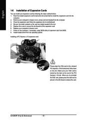
... the card. Make sure your expansion card by the latch at the end of the PCI Express x 16 slot. GA-8I945P (Pro)(-G) Motherboard - 16 - Be sure the metal contacts on the card are indeed seated in motherboard. 4. When you try uninstall the VGA card, please press the latch as the picture to the left shows...
... the card. Make sure your expansion card by the latch at the end of the PCI Express x 16 slot. GA-8I945P (Pro)(-G) Motherboard - 16 - Be sure the metal contacts on the card are indeed seated in motherboard. 4. When you try uninstall the VGA card, please press the latch as the picture to the left shows...
Manual
Page 18
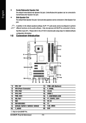
... (Power Connector) 3) CPU_FAN 4) SYS_FAN 5) PWR_FAN 6) NB_FAN 7) FDD 8) IDE1/IDE2/IDE3 9) SATAII0 / SATAII1 / SATAII2 / SATAII3 10) F_AUDIO Only for GA-8I945P Pro. PWR_LED (Optional) F_PANEL CD_IN SPDIF_I F_USB/GREEN_USB F1_1394/F2_1394 RF_ID CI CLR_CMOS BAT GA-8I945P (Pro)(-G) Motherboard 11) 12) 13) 14) 15) 16) 17) 18) 19) 20) - 18 - Surround side speakers can be connected to the...
... (Power Connector) 3) CPU_FAN 4) SYS_FAN 5) PWR_FAN 6) NB_FAN 7) FDD 8) IDE1/IDE2/IDE3 9) SATAII0 / SATAII1 / SATAII2 / SATAII3 10) F_AUDIO Only for GA-8I945P Pro. PWR_LED (Optional) F_PANEL CD_IN SPDIF_I F_USB/GREEN_USB F1_1394/F2_1394 RF_ID CI CLR_CMOS BAT GA-8I945P (Pro)(-G) Motherboard 11) 12) 13) 14) 15) 16) 17) 18) 19) 20) - 18 - Surround side speakers can be connected to the...

Manual
Page 20
...CPU_FAN / SYS_FAN / PWR_FAN (Cooler Fan Power Connector) The cooler fan power connector supplies a +12V power voltage via a 3-pin/4-pin (only for GA-8I945P Pro. Please remember to connect the power to the cooler to prevent CPU overheating and failure. 1 CPU_FAN 1 SYS_FAN/ PWR_FAN Pin No. 1 2 3 ... If you installed wrong direction, the chip fan will damage the chip fan. (Usually black cable is the ground wire (GND). GA-8I945P (Pro)(-G) Motherboard - 20 - A red power connector wire indicates a positive connection and requires a +12V power voltage. Most coolers are designed with color...
...CPU_FAN / SYS_FAN / PWR_FAN (Cooler Fan Power Connector) The cooler fan power connector supplies a +12V power voltage via a 3-pin/4-pin (only for GA-8I945P Pro. Please remember to connect the power to the cooler to prevent CPU overheating and failure. 1 CPU_FAN 1 SYS_FAN/ PWR_FAN Pin No. 1 2 3 ... If you installed wrong direction, the chip fan will damage the chip fan. (Usually black cable is the ground wire (GND). GA-8I945P (Pro)(-G) Motherboard - 20 - A red power connector wire indicates a positive connection and requires a +12V power voltage. Most coolers are designed with color...
Manual
Page 22
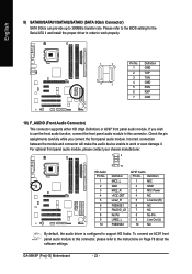
... chassis manufacturer. 1 2 HD Audio: Pin No. 1 2 3 4 5 6 7 8 9 10 9 10 Definition MIC2_L GND MIC2_R -ACZ_DET Line2_R FSENSE1 FAUDIO_JD No Pin LINE2_L FSENSE2 AC'97 Audio: Pin No. GA-8I945P (Pro)(-G) Motherboard - 22 - Definition 1 MIC 2 GND 3 MIC Power 4 NC 5 Line Out (R) 6 NC 7 NC 8 No Pin 9 Line Out (L) 10 NC By default, the audio driver is configured to...
... chassis manufacturer. 1 2 HD Audio: Pin No. 1 2 3 4 5 6 7 8 9 10 9 10 Definition MIC2_L GND MIC2_R -ACZ_DET Line2_R FSENSE1 FAUDIO_JD No Pin LINE2_L FSENSE2 AC'97 Audio: Pin No. GA-8I945P (Pro)(-G) Motherboard - 22 - Definition 1 MIC 2 GND 3 MIC Power 4 NC 5 Line Out (R) 6 NC 7 NC 8 No Pin 9 Line Out (L) 10 NC By default, the audio driver is configured to...
Manual
Page 24
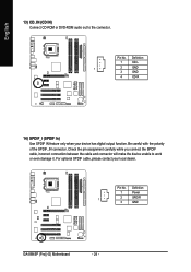
Be careful with the polarity of the SPDIF_IN connector. Definition 1 Power 1 2 SPDIFI 3 GND GA-8I945P (Pro)(-G) Motherboard - 24 - For optional SPDIF cable, please contact your device has digital output function. Check the pin assignment carefully while you connect the SPDIF cable, incorrect ...
Be careful with the polarity of the SPDIF_IN connector. Definition 1 Power 1 2 SPDIFI 3 GND GA-8I945P (Pro)(-G) Motherboard - 24 - For optional SPDIF cable, please contact your device has digital output function. Check the pin assignment carefully while you connect the SPDIF cable, incorrect ...
Manual
Page 26
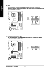
... to detect if the chassis cover is removed. Pin No. Definition 1 1 Signal 2 GND GA-8I945P (Pro)(-G) Motherboard - 26 - Definition 1 Power 1 2 RFID_RI- 3 RF_TXD 4 RF_RXD 5 NC 6 GND 18) CI (Chassis Intrusion, Case Open) This 2-pin connector allows your nearest dealer for the optional GIGABYTE external device. English 17) RF_ID This connector allows you connect the external device...
... to detect if the chassis cover is removed. Pin No. Definition 1 1 Signal 2 GND GA-8I945P (Pro)(-G) Motherboard - 26 - Definition 1 Power 1 2 RFID_RI- 3 RF_TXD 4 RF_RXD 5 NC 6 GND 18) CI (Chassis Intrusion, Case Open) This 2-pin connector allows your nearest dealer for the optional GIGABYTE external device. English 17) RF_ID This connector allows you connect the external device...
Manual
Page 28
English GA-8I945P (Pro)(-G) Motherboard - 28 -
English GA-8I945P (Pro)(-G) Motherboard - 28 -
Manual
Page 29
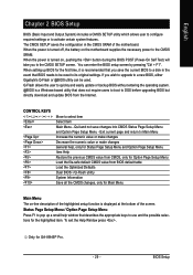
... the appropriate keys to use and the possible selections for Main Menu Main Menu The on the motherboard supplies the necessary power to Main Menu Increase the numeric value or make changes Decrease the numeric ... BIOS to a disk in the CMOS SRAM of the screen. You can be reset to a new BIOS, either Gigabyte's Q-Flash or @BIOS utility can enter the BIOS setup screen by pressing "Ctrl + F1". English Chapter 2 BIOS... / Option Page Setup Menu Press F1 to pop up BIOS for GA-8I945P Pro. - 29 - BIOS Setup The CMOS SETUP saves the configuration in the event that BIOS needs to be ...
... the appropriate keys to use and the possible selections for Main Menu Main Menu The on the motherboard supplies the necessary power to Main Menu Increase the numeric value or make changes Decrease the numeric ... BIOS to a disk in the CMOS SRAM of the screen. You can be reset to a new BIOS, either Gigabyte's Q-Flash or @BIOS utility can enter the BIOS setup screen by pressing "Ctrl + F1". English Chapter 2 BIOS... / Option Page Setup Menu Press F1 to pop up BIOS for GA-8I945P Pro. - 29 - BIOS Setup The CMOS SETUP saves the configuration in the event that BIOS needs to be ...
Manual
Page 30
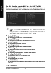
Use arrow keys to select among the items and press to the default for GA-8I945P Pro. Please Load Optimized Defaults in safe configuration. English The Main Menu (For example: BIOS Ver. : GA-8I945P Pro F2a) Once you want, please press "Ctrl+F1" to search the advanced ...) will appear on the screen. If you can't find the setting you enter Award BIOS CMOS Setup Utility, the Main Menu (as usual. GA-8I945P (Pro)(-G) Motherboard - 30 - CMOS Setup Utility-Copyright (C) 1984-2005 Award Software ` Standard CMOS Features ` Advanced BIOS Features ` Integrated Peripherals ` Power Management ...
Use arrow keys to select among the items and press to the default for GA-8I945P Pro. Please Load Optimized Defaults in safe configuration. English The Main Menu (For example: BIOS Ver. : GA-8I945P Pro F2a) Once you want, please press "Ctrl+F1" to search the advanced ...) will appear on the screen. If you can't find the setting you enter Award BIOS CMOS Setup Utility, the Main Menu (as usual. GA-8I945P (Pro)(-G) Motherboard - 30 - CMOS Setup Utility-Copyright (C) 1984-2005 Award Software ` Standard CMOS Features ` Advanced BIOS Features ` Integrated Peripherals ` Power Management ...
Manual
Page 32
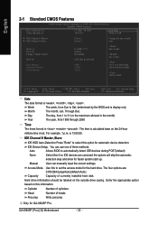
... 511M 512M Sun. IDE Channel 0 Master, Slave IDE HDD Auto-Detection Press "Enter" to Sat. Hard drive information should be labeled on this option for GA-8I945P Pro. Cylinder Number of cylinders Head Number of currently installed hard disk. GA-8I945P (Pro)(-G) Motherboard - 32 -
... 511M 512M Sun. IDE Channel 0 Master, Slave IDE HDD Auto-Detection Press "Enter" to Sat. Hard drive information should be labeled on this option for GA-8I945P Pro. Cylinder Number of cylinders Head Number of currently installed hard disk. GA-8I945P (Pro)(-G) Motherboard - 32 -
Manual
Page 34
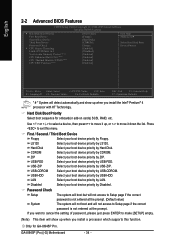
... automatically and show up when you install a processor which supports this menu. First / Second / Third Boot Device Floppy Select your boot device priority by LS120. GA-8I945P (Pro)(-G) Motherboard - 34 - English 2-2 Advanced BIOS Features CMOS Setup Utility-Copyright (C) 1984-2005 Award Software Advanced BIOS Features ` Hard Disk Boot Priority First Boot Device Second Boot... to move it down the list. ZIP USB-FDD Select your boot device priority by USB-FDD. Hard Disk Boot Priority Select boot sequence for GA-8I945P Pro.
... automatically and show up when you install a processor which supports this menu. First / Second / Third Boot Device Floppy Select your boot device priority by LS120. GA-8I945P (Pro)(-G) Motherboard - 34 - English 2-2 Advanced BIOS Features CMOS Setup Utility-Copyright (C) 1984-2005 Award Software Advanced BIOS Features ` Hard Disk Boot Priority First Boot Device Second Boot... to move it down the list. ZIP USB-FDD Select your boot device priority by USB-FDD. Hard Disk Boot Priority Select boot sequence for GA-8I945P Pro.
Manual
Page 36
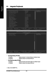
GA-8I945P (Pro)(-G) Motherboard - 36 - Only for GA-8I945P Pro. On-Chip Secondary PCI IDE Enabled Enable onboard 2nd channel IDE port. (Default value) Disabled Disable onboard 2nd channel IDE port. English 2-3 Integrated Peripherals CMOS ...
GA-8I945P (Pro)(-G) Motherboard - 36 - Only for GA-8I945P Pro. On-Chip Secondary PCI IDE Enabled Enable onboard 2nd channel IDE port. (Default value) Disabled Disable onboard 2nd channel IDE port. English 2-3 Integrated Peripherals CMOS ...


