
Manual
Page 1
GA-8I945GME Intel® Pentium® 4 LGA775 Processor Motherboard User's Manual Rev. 1002 12ME-945GME-1002R * The WEEE marking on the product indicates this product must not be disposed of with user's other household waste and must be handed over to a designated collection point for the recycling of waste electrical and electronic equipment!! * The WEEE marking applies only in European Union's member states.
GA-8I945GME Intel® Pentium® 4 LGA775 Processor Motherboard User's Manual Rev. 1002 12ME-945GME-1002R * The WEEE marking on the product indicates this product must not be disposed of with user's other household waste and must be handed over to a designated collection point for the recycling of waste electrical and electronic equipment!! * The WEEE marking applies only in European Union's member states.

Manual
Page 2
Motherboard GA-8I945GME Dec. 10, 2005 Motherboard GA-8I945GME Dec. 10, 2005
Motherboard GA-8I945GME Dec. 10, 2005 Motherboard GA-8I945GME Dec. 10, 2005

Manual
Page 4
Table of Contents GA-8I945GME Motherboard Layout 6 Block Diagram ...7 Chapter 1 Hardware Installation 9 1-1 Considerations Prior to Installation 9 1-2 Feature Summary 10 1-3 Installation of the CPU and Heatsink 12 1-3-1 Installation of the CPU 12 1-3-2 ...
Table of Contents GA-8I945GME Motherboard Layout 6 Block Diagram ...7 Chapter 1 Hardware Installation 9 1-1 Considerations Prior to Installation 9 1-2 Feature Summary 10 1-3 Installation of the CPU and Heatsink 12 1-3-1 Installation of the CPU 12 1-3-2 ...

Manual
Page 6
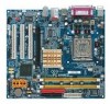
GA-8I945GME Motherboard Layout KB_MS ATX_12V LGA775 CPU_FAN IT8712F COMA GA-8I945GME ATX LPT LAN VGA R_USB USB SYS_FAN AUDIO F_AUDIO PCIE_16 PCI1 RTL 8110S PCI2 SPDIF_IO CODEC PCI3 SUR_CEN CD_IN AUX_IN COMB Intel 945G DDRII2 DDRII1 IDE FDD SATAIIO SATAII2 SATAII1 SATAII3 ICH7 BAT CI BIOS TPM PWR_LED CLR_CMOS F_USB1F_USB2 F_PANEL - 6 -
GA-8I945GME Motherboard Layout KB_MS ATX_12V LGA775 CPU_FAN IT8712F COMA GA-8I945GME ATX LPT LAN VGA R_USB USB SYS_FAN AUDIO F_AUDIO PCIE_16 PCI1 RTL 8110S PCI2 SPDIF_IO CODEC PCI3 SUR_CEN CD_IN AUX_IN COMB Intel 945G DDRII2 DDRII1 IDE FDD SATAIIO SATAII2 SATAII1 SATAII3 ICH7 BAT CI BIOS TPM PWR_LED CLR_CMOS F_USB1F_USB2 F_PANEL - 6 -
Manual
Page 7
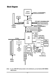
... Center/Subwoofer Speaker Out Side Speaker Out MIC Line-Out Line-In SPDIF In SPDIF Out (Note) To use a DDRII 667 memory module on the motherboard, you must install an 800/1066MHz FSB processor . - 7 -
... Center/Subwoofer Speaker Out Side Speaker Out MIC Line-Out Line-In SPDIF In SPDIF Out (Note) To use a DDRII 667 memory module on the motherboard, you must install an 800/1066MHz FSB processor . - 7 -
Manual
Page 9
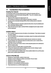
... Preparing Your Computer The motherboard contains numerous delicate electronic circuits and components which can lead to damage to system components as well as a result of violating the conditions recommended in the user manual. 3. Damage due to be an unofficial Gigabyte product. - 9 -...the use of an antistatic pad or within the computer casing. 6. Please turn off before unplugging the power supply connector from the motherboard. Installation Notices 1. These stickers are uncertain about any metal leads or connectors. 3. If you are required for warranty validation. ...
... Preparing Your Computer The motherboard contains numerous delicate electronic circuits and components which can lead to damage to system components as well as a result of violating the conditions recommended in the user manual. 3. Damage due to be an unofficial Gigabyte product. - 9 -...the use of an antistatic pad or within the computer casing. 6. Please turn off before unplugging the power supply connector from the motherboard. Installation Notices 1. These stickers are uncertain about any metal leads or connectors. 3. If you are required for warranty validation. ...

Manual
Page 10
... connector Š 2 USB 2.0/1.1 connectors for additional 4 USB 2.0/1.1 ports by cables Š 1 SUR_CEN connector Š 1 SPDIF In/Out connector Š 1 power LED connector Š 1 TPM connector GA-8I945GME Motherboard - 10 -
... connector Š 2 USB 2.0/1.1 connectors for additional 4 USB 2.0/1.1 ports by cables Š 1 SUR_CEN connector Š 1 SPDIF In/Out connector Š 1 power LED connector Š 1 TPM connector GA-8I945GME Motherboard - 10 -

Manual
Page 11
... Internet Security (OEM version) Form Factor Š Micro ATX form factor; 24.4cm x 22.0cm (Note 1) For further CPU support information, please go to GIGABYTE's website. (Note 2) To use a DDRII 667 memory module on the motherboard, you must install an 800/1066MHz FSB processor . (Note 3) EasyTune functions may vary depending on different...
... Internet Security (OEM version) Form Factor Š Micro ATX form factor; 24.4cm x 22.0cm (Note 1) For further CPU support information, please go to GIGABYTE's website. (Note 2) To use a DDRII 667 memory module on the motherboard, you must install an 800/1066MHz FSB processor . (Note 3) EasyTune functions may vary depending on different...

Manual
Page 12
... Installation of the CPU Metal Lever Fig. 1 Gently lift the metal lever located on the CPU prior to the CPU during installation.) GA-8I945GME Motherboard - 12 - If this occurs, please change the insert direction of the following conditions: 1. Chipset: An Intel® Chipset that the... motherboard supports the CPU. 2. Align the indented corner of heat sink paste between your hardware specifications including the CPU, graphics card, memory, hard drive, ...
... Installation of the CPU Metal Lever Fig. 1 Gently lift the metal lever located on the CPU prior to the CPU during installation.) GA-8I945GME Motherboard - 12 - If this occurs, please change the insert direction of the following conditions: 1. Chipset: An Intel® Chipset that the... motherboard supports the CPU. 2. Align the indented corner of heat sink paste between your hardware specifications including the CPU, graphics card, memory, hard drive, ...

Manual
Page 13
... before installation. (This instruction is complete. If the push pin is inserted as a result of hardening of the heatsink to the pin hole on the motherboard.Pressing down the push pins diagonally. Hardware Installation The heatsink may adhere to the CPU as the picture, the installation is only for Intel boxed... Male Push Pin The top of Female Push Pin Female Push Pin Fig.1 Please apply an even layer of heatsink paste on the surface of motherboard after installing. Fig. 4 Please make sure the push pins aim to the CPU fan header located on the...
... before installation. (This instruction is complete. If the push pin is inserted as a result of hardening of the heatsink to the pin hole on the motherboard.Pressing down the push pins diagonally. Hardware Installation The heatsink may adhere to the CPU as the picture, the installation is only for Intel boxed... Male Push Pin The top of Female Push Pin Female Push Pin Fig.1 Please apply an even layer of heatsink paste on the surface of motherboard after installing. Fig. 4 Please make sure the push pins aim to the CPU fan header located on the...

Manual
Page 14
...module, please switch the direction. Before installing or removing memory modules, please make sure that the computer power is supported by the motherboard. The memory capacity used . 2. If you wish to lock the DIMM module. Reverse the installation steps when you are designed so..., whereby BIOS will automatically detect memory capacity and specifications. Then push it down. A memory module can differ with the following conditions: 1. GA-8I945GME Motherboard - 14 - It is recommended that they can only fit in only one direction. Notch DDR II Fig.1 The DIMM socket has a notch...
...module, please switch the direction. Before installing or removing memory modules, please make sure that the computer power is supported by the motherboard. The memory capacity used . 2. If you wish to lock the DIMM module. Reverse the installation steps when you are designed so..., whereby BIOS will automatically detect memory capacity and specifications. Then push it down. A memory module can differ with the following conditions: 1. GA-8I945GME Motherboard - 14 - It is recommended that they can only fit in only one direction. Notch DDR II Fig.1 The DIMM socket has a notch...

Manual
Page 16
... Cards You can install your computer's chassis cover, screws and slot bracket from the operating system. Make sure your computer's chassis cover. 7. GA-8I945GME Motherboard - 16 - Be sure the metal contacts on the slot. Install related driver from the computer. 3. When you try uninstall the VGA card...picture to the left shows to the onboard PCI Express x 16 slot and press firmly down on the card are indeed seated in motherboard. 4. Read the related expansion card's instruction document before install the expansion card into expansion slot in the slot. 5. Replace the ...
... Cards You can install your computer's chassis cover, screws and slot bracket from the operating system. Make sure your computer's chassis cover. 7. GA-8I945GME Motherboard - 16 - Be sure the metal contacts on the slot. Install related driver from the computer. 3. When you try uninstall the VGA card...picture to the left shows to the onboard PCI Express x 16 slot and press firmly down on the card are indeed seated in motherboard. 4. Read the related expansion card's instruction document before install the expansion card into expansion slot in the slot. 5. Replace the ...
Manual
Page 18
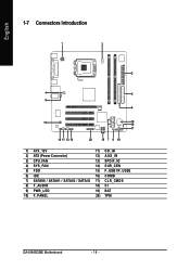
English 1-7 Connectors Introduction 1 3 2 4 5 8 6 13 19 18 17 14 11 12 16 20 15 7 9 10 1) ATX_12V 11) CD_IN 2) ATX (Power Connector) 12) AUX_IN 3) CPU_FAN 13) SPDIF_IO 4) SYS_FAN 14) SUR_CEN 5) FDD 15) F_USB1/F_USB2 6) IDE 16) COMB 7) SATAII0 / SATAII1 / SATAII2 / SATAII3 17) CLR_CMOS 8) F_AUDIO 18) CI 9) PWR_LED 19) BAT 10) F_PANEL 20) TPM GA-8I945GME Motherboard - 18 -
English 1-7 Connectors Introduction 1 3 2 4 5 8 6 13 19 18 17 14 11 12 16 20 15 7 9 10 1) ATX_12V 11) CD_IN 2) ATX (Power Connector) 12) AUX_IN 3) CPU_FAN 13) SPDIF_IO 4) SYS_FAN 14) SUR_CEN 5) FDD 15) F_USB1/F_USB2 6) IDE 16) COMB 7) SATAII0 / SATAII1 / SATAII2 / SATAII3 17) CLR_CMOS 8) F_AUDIO 18) CI 9) PWR_LED 19) BAT 10) F_PANEL 20) TPM GA-8I945GME Motherboard - 18 -

Manual
Page 19
... and devices are properly installed. If you use a power supply that all the components on the motherboard. Definition Pin No. Align the power connector with its proper location on the motherboard before plugging in the power cord ; Before connecting the power connector, please make sure that is...to handle the system voltage requirements. Please use a 24-pin ATX power supply, please remove the small cover on the power connector on the motherboard and connect tightly. Caution! If the ATX_12V power connector is not connected, the system will not start . If a power supply is used...
... and devices are properly installed. If you use a power supply that all the components on the motherboard. Definition Pin No. Align the power connector with its proper location on the motherboard before plugging in the power cord ; Before connecting the power connector, please make sure that is...to handle the system voltage requirements. Please use a 24-pin ATX power supply, please remove the small cover on the power connector on the motherboard and connect tightly. Caution! If the ATX_12V power connector is not connected, the system will not start . If a power supply is used...

Manual
Page 20
... drives supported are designed with color-coded power connector wires. Please remember to connect the power to the cooler to the pin1 position. 34 33 GA-8I945GME Motherboard 2 1 - 20 -
... drives supported are designed with color-coded power connector wires. Please remember to connect the power to the cooler to the pin1 position. 34 33 GA-8I945GME Motherboard 2 1 - 20 -

Manual
Page 22
... indicator to utilize the front audio header, your dealer. In order to indicate whether the system is the same as the pin assigment on /off. GA-8I945GME Motherboard - 22 - Please note, you are buying support front audio connector, please contact your chassis must remove 5-6, 9-10 Jumper. Also please make sure the pin assigment...
... indicator to utilize the front audio header, your dealer. In order to indicate whether the system is the same as the pin assigment on /off. GA-8I945GME Motherboard - 22 - Please note, you are buying support front audio connector, please contact your chassis must remove 5-6, 9-10 Jumper. Also please make sure the pin assigment...

Manual
Page 24
Pin No. Definition 1 CD-L 1 2 GND 3 GND 4 CD-R 12) AUX_IN (AUX In Connector) Connect other device (such as PCI TV Tunner audio out) to the connector. English 11) CD_IN (CD IN) Connect CD-ROM or DVD-ROM audio out to the connector. Definition 1 AUX-L 2 GND 1 3 GND 4 AUX-R GA-8I945GME Motherboard - 24 - Pin No.
Pin No. Definition 1 CD-L 1 2 GND 3 GND 4 CD-R 12) AUX_IN (AUX In Connector) Connect other device (such as PCI TV Tunner audio out) to the connector. English 11) CD_IN (CD IN) Connect CD-ROM or DVD-ROM audio out to the connector. Definition 1 AUX-L 2 GND 1 3 GND 4 AUX-R GA-8I945GME Motherboard - 24 - Pin No.

Manual
Page 26
... connector. For optional front USB cable, please contact your nearest dealer for optional COMB cable. 2 10 1 9 Pin No. 1 2 3 4 5 6 7 8 9 10 Definition NDCDBNSINB NSOUTB NDTRBGND NDSRBNRTSBNCTSBNRIBNo Pin GA-8I945GME Motherboard - 26 - Check the pin assignments while you connect the front USB cable, incorrect connection between the cable and connector will make the device unable to...
... connector. For optional front USB cable, please contact your nearest dealer for optional COMB cable. 2 10 1 9 Pin No. 1 2 3 4 5 6 7 8 9 10 Definition NDCDBNSINB NSOUTB NDTRBGND NDSRBNRTSBNCTSBNRIBNo Pin GA-8I945GME Motherboard - 26 - Check the pin assignments while you connect the front USB cable, incorrect connection between the cable and connector will make the device unable to...

Manual
Page 28
... LAD1 19 Pin No. 11 12 13 14 15 16 17 18 19 20 Definition LAD0 GND RSVO RSV1 SB3V SERIRQ GND CLKRUN LPCPD RSV2 GA-8I945GME Motherboard - 28 - Replace only with the same or equivalent type recommended by the manufacturer. 19) BAT(Battery) English Danger of used batteries according to erase CMOS...
... LAD1 19 Pin No. 11 12 13 14 15 16 17 18 19 20 Definition LAD0 GND RSVO RSV1 SB3V SERIRQ GND CLKRUN LPCPD RSV2 GA-8I945GME Motherboard - 28 - Replace only with the same or equivalent type recommended by the manufacturer. 19) BAT(Battery) English Danger of used batteries according to erase CMOS...

Manual
Page 31
... utility which allows user to configure required settings or to select item Select Item Main Menu - You can be reset to a new BIOS, either Gigabyte's Q-Flash or @BIOS utility can enter the BIOS setup screen by pressing "Ctrl + F1". CONTROL KEYS Enter> Move to activate certain system features...you wish to upgrade to its original settings. Because BIOS flashing is potentially risky, please do it is displayed at the bottom of the motherboard. The CMOS SETUP saves the configuration in the CMOS SRAM of the screen. When the power is turned on -line description of the ...
... utility which allows user to configure required settings or to select item Select Item Main Menu - You can be reset to a new BIOS, either Gigabyte's Q-Flash or @BIOS utility can enter the BIOS setup screen by pressing "Ctrl + F1". CONTROL KEYS Enter> Move to activate certain system features...you wish to upgrade to its original settings. Because BIOS flashing is potentially risky, please do it is displayed at the bottom of the motherboard. The CMOS SETUP saves the configuration in the CMOS SRAM of the screen. When the power is turned on -line description of the ...


