Manual
Page 1
GA-8I915P Duo (Pro) Intel® Pentium® 4 LGA775 Processor Motherboard User's Manual Rev. 1303 12ME-8I915PUP-1303
GA-8I915P Duo (Pro) Intel® Pentium® 4 LGA775 Processor Motherboard User's Manual Rev. 1303 12ME-8I915PUP-1303
Manual
Page 2
Motherboard GA-8I915P Duo (Pro) Jul. 2, 2004 Motherboard GA-8I915P Duo (Pro) Jul. 2, 2004
Motherboard GA-8I915P Duo (Pro) Jul. 2, 2004 Motherboard GA-8I915P Duo (Pro) Jul. 2, 2004
Manual
Page 3
....tw Copyright © 2005 GIGA-BYTE TECHNOLOGY CO., LTD. No part of this product is the property of this product, Gigabyte has categorized the user manual in the following: „ For quick installation, please refer to the "Hardware Installation Guide" included with this manual may... be reproduced, copied, translated, or transmitted in the use of Gigabyte. Product Manual Classification In order to assist in any form or by any means without prior notice. All rights reserved.
....tw Copyright © 2005 GIGA-BYTE TECHNOLOGY CO., LTD. No part of this product is the property of this product, Gigabyte has categorized the user manual in the following: „ For quick installation, please refer to the "Hardware Installation Guide" included with this manual may... be reproduced, copied, translated, or transmitted in the use of Gigabyte. Product Manual Classification In order to assist in any form or by any means without prior notice. All rights reserved.
Manual
Page 4
Table of Contents GA-8I915P Duo (Pro) Motherboard Layout 6 Block Diagram ...7 Chapter 1 Hardware Installation 9 1-1 Considerations Prior to Installation 9 1-2 Feature Summary 10 1-3 Installation of the CPU and Heatsink 12 1-3-1 Installation of the CPU ...
Table of Contents GA-8I915P Duo (Pro) Motherboard Layout 6 Block Diagram ...7 Chapter 1 Hardware Installation 9 1-1 Considerations Prior to Installation 9 1-2 Feature Summary 10 1-3 Installation of the CPU and Heatsink 12 1-3-1 Installation of the CPU ...
Manual
Page 5
Chapter 3 Install Drivers 49 3-1 Install Chipset Drivers 49 3-2 Software Applications 50 3-3 Driver CD Information 50 3-4 Hardware Information 51 3-5 Contact Us ...51 Chapter 4 Appendix 53 4-1 Unique Software Utilities 53 4-1-1 Xpress Recovery Introduction 54 4-1-2 Flash BIOS Method Introduction 57 4-1-3 Serial ATA BIOS Setting Utility Introduction 68 4-1-4 2 / 4 / 5.1 / 7.1 Channel Audio Function Introduction 75 4-2 Troubleshooting 81 Only for GA-8I915P Duo Pro. - 5 -
Chapter 3 Install Drivers 49 3-1 Install Chipset Drivers 49 3-2 Software Applications 50 3-3 Driver CD Information 50 3-4 Hardware Information 51 3-5 Contact Us ...51 Chapter 4 Appendix 53 4-1 Unique Software Utilities 53 4-1-1 Xpress Recovery Introduction 54 4-1-2 Flash BIOS Method Introduction 57 4-1-3 Serial ATA BIOS Setting Utility Introduction 68 4-1-4 2 / 4 / 5.1 / 7.1 Channel Audio Function Introduction 75 4-2 Troubleshooting 81 Only for GA-8I915P Duo Pro. - 5 -
Manual
Page 6
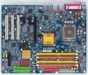
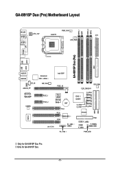
GA-8I915P Duo (Pro) Motherboard Layout DDRII_2 DDRII_1 DDR1 DDR2 PWR_FAN KB_MS ATX_12V LGA775 ATX SPDIF_O SPDIF_I CPU_FAN COMA LPT IDE1 GA-8I915P Duo (Pro) USB USB LAN2 LAN1 AUDIO1 AUDIO2 CD_IN AZALIA_FP Broadcom 5751 /5789 NB_FAN Broadcom 5751/5789 PCIE_1 CODEC PCIE_2 IT8712 IR Intel 915P PCIE_16 CLR_CMOS SYS_FAN Main BIOS Backup BIOS BAT PCI1 PCI2 TSB43AB23 PCI3 F1_1394 ICH6 / ICH6R S_ATA3 S_ATA2 S_ATA1 S_ATA0 VT6410 IDE3 FDD F_USB2 F_PANEL F_USB1 IDE2 F2_1394 PWR_LED Only for GA-8I915P Duo. - 6 - Only for GA-8I915P Duo Pro.
GA-8I915P Duo (Pro) Motherboard Layout DDRII_2 DDRII_1 DDR1 DDR2 PWR_FAN KB_MS ATX_12V LGA775 ATX SPDIF_O SPDIF_I CPU_FAN COMA LPT IDE1 GA-8I915P Duo (Pro) USB USB LAN2 LAN1 AUDIO1 AUDIO2 CD_IN AZALIA_FP Broadcom 5751 /5789 NB_FAN Broadcom 5751/5789 PCIE_1 CODEC PCIE_2 IT8712 IR Intel 915P PCIE_16 CLR_CMOS SYS_FAN Main BIOS Backup BIOS BAT PCI1 PCI2 TSB43AB23 PCI3 F1_1394 ICH6 / ICH6R S_ATA3 S_ATA2 S_ATA1 S_ATA0 VT6410 IDE3 FDD F_USB2 F_PANEL F_USB1 IDE2 F2_1394 PWR_LED Only for GA-8I915P Duo. - 6 - Only for GA-8I915P Duo Pro.
Manual
Page 7
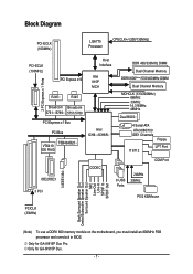
Only for GA-8I915P Duo Pro. Only for GA-8I915P Duo. - 7 - Block Diagram PCI-ECLK (100MHz) LGA775 Processor CPUCLK+/-(200/133MHz) PCI-ECLK (100MHz) PCI Express x16 Host Interface Intel 915P MCH 2 PCI Express x 1 Ports RJ45 ...
Only for GA-8I915P Duo Pro. Only for GA-8I915P Duo. - 7 - Block Diagram PCI-ECLK (100MHz) LGA775 Processor CPUCLK+/-(200/133MHz) PCI-ECLK (100MHz) PCI Express x16 Host Interface Intel 915P MCH 2 PCI Express x 1 Ports RJ45 ...
Manual
Page 9
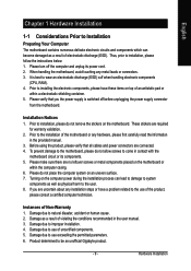
... cause. 2. Please do not place the computer system on top of the motherboard or any metal leads or connectors. 3. Thus, prior to be an unofficial Gigabyte product. - 9 - Please verify that all cables and power connectors are required for warranty validation. 2. These stickers are connected. 4. Product determined to installation, please follow the...
... cause. 2. Please do not place the computer system on top of the motherboard or any metal leads or connectors. 3. Thus, prior to be an unofficial Gigabyte product. - 9 - Please verify that all cables and power connectors are required for warranty validation. 2. These stickers are connected. 4. Product determined to installation, please follow the...

Manual
Page 10
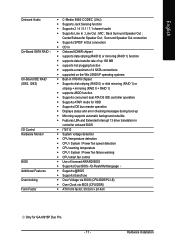
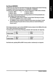
... 45 port--LAN1 / LAN2 (Note) To use a DDRII 600 memory module on the motherboard, you must install an 800MHz FSB processor and overclock in BIOS. GA-8I915P Duo (Pro) Motherboard - 10 - Only for GA-8I915P Duo. Only for GA-8I915P Duo Pro.
... 45 port--LAN1 / LAN2 (Note) To use a DDRII 600 memory module on the motherboard, you must install an 800MHz FSB processor and overclock in BIOS. GA-8I915P Duo (Pro) Motherboard - 10 - Only for GA-8I915P Duo. Only for GA-8I915P Duo Pro.
Manual
Page 11
... Š Over Voltage via BIOS (CPU/DDR/PCI-E) Š Over Clock via BIOS (CPU/DDR) Š ATX form factor; 30.5cm x 24.4cm Only for GA-8I915P Duo Pro. - 11 - MIC ; Hardware Installation Center/Subwoofer Speaker Out ;
... Š Over Voltage via BIOS (CPU/DDR/PCI-E) Š Over Clock via BIOS (CPU/DDR) Š ATX form factor; 30.5cm x 24.4cm Only for GA-8I915P Duo Pro. - 11 - MIC ; Hardware Installation Center/Subwoofer Speaker Out ;
Manual
Page 12
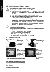
... computer system requires all of the CPU socket. Fig. 3 Notice the small gold colored triangle located on the CPU socket to the CPU during installation.) GA-8I915P Duo (Pro) Motherboard - 12 - Fig. 4 Once the CPU is installed on the CPU socket.
... computer system requires all of the CPU socket. Fig. 3 Notice the small gold colored triangle located on the CPU socket to the CPU during installation.) GA-8I915P Duo (Pro) Motherboard - 12 - Fig. 4 Once the CPU is installed on the CPU socket.
Manual
Page 13
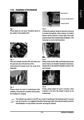
Fig. 4 Please make sure the push pins aim to the pin hole on the motherboard. The heatsink may adhere to the CPU as the picture, the installation is suggested that either thermal tape rather than heat sink paste be used for detailed installation instructions, please refer to the heatsink installation section of the user manual) Fig. 5 Please check the back of motherboard after installing. Hardware Installation If the push pin is inserted as a result of hardening of arrow sign on the male push pin doesn't face inwards before installation. (This instruction is only for Intel ...
Fig. 4 Please make sure the push pins aim to the pin hole on the motherboard. The heatsink may adhere to the CPU as the picture, the installation is suggested that either thermal tape rather than heat sink paste be used for detailed installation instructions, please refer to the heatsink installation section of the user manual) Fig. 5 Please check the back of motherboard after installing. Hardware Installation If the push pin is inserted as a result of hardening of arrow sign on the male push pin doesn't face inwards before installation. (This instruction is only for Intel ...
Manual
Page 14
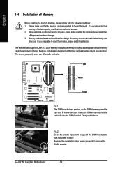
... you wish to lock the DIMM module. DDR Notch DDR II Fig.1 The DIMM socket has a notch, so the DIMM memory module can be used. 2. GA-8I915P Duo (Pro) Motherboard - 14 - It is recommended that they can differ with the following conditions: 1. Before installing or removing memory modules, please make sure that the computer...
... you wish to lock the DIMM module. DDR Notch DDR II Fig.1 The DIMM socket has a notch, so the DIMM memory module can be used. 2. GA-8I915P Duo (Pro) Motherboard - 14 - It is recommended that they can differ with the following conditions: 1. Before installing or removing memory modules, please make sure that the computer...
Manual
Page 15
... Channel Technology, the bandwidth of Intel chipset specifications. 1. The following explanations due to work. English Dual Channel DDR/DDR II GA-8I915P Duo (Pro) supports the Dual Channel Technology. Two DDR/DDR II memory modules are installed (the same memory size and type): The Dual... with the same color in order for Dual Channel Technology to the limitation of Memory Bus will add double up to 6.4GB/s(DDR) ; 8.5GB(DDRII) GA-8I915P Duo (Pro) includes 4 DIMM sockets, and each Channel has two DIMM sockets as following: Channel A : DDR 1 or Channel A : DDR II 1 Channel B : ...
... Channel Technology, the bandwidth of Intel chipset specifications. 1. The following explanations due to work. English Dual Channel DDR/DDR II GA-8I915P Duo (Pro) supports the Dual Channel Technology. Two DDR/DDR II memory modules are installed (the same memory size and type): The Dual... with the same color in order for Dual Channel Technology to the limitation of Memory Bus will add double up to 6.4GB/s(DDR) ; 8.5GB(DDRII) GA-8I915P Duo (Pro) includes 4 DIMM sockets, and each Channel has two DIMM sockets as following: Channel A : DDR 1 or Channel A : DDR II 1 Channel B : ...
Manual
Page 16
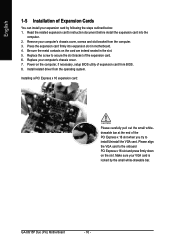
... onboard PCI Express x 16 slot and press firmly down on the slot .Make sure your VGA card is locked by following the steps outlined below: 1. GA-8I915P Duo (Pro) Motherboard - 16 - Replace your computer's chassis cover. 7. Be sure the metal contacts on the computer, if necessary, setup BIOS utility of the expansion card. 6. Power...
... onboard PCI Express x 16 slot and press firmly down on the slot .Make sure your VGA card is locked by following the steps outlined below: 1. GA-8I915P Duo (Pro) Motherboard - 16 - Replace your computer's chassis cover. 7. Be sure the metal contacts on the computer, if necessary, setup BIOS utility of the expansion card. 6. Power...
Manual
Page 17
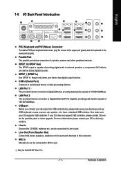
... function. MIC In Microphone can be connected to Line In jack. If your OS does not support USB controller, please contact OS ven dor for GA-8I915P Duo Pro. - 17 - For more information please contact your OS supports USB controller. USB port Before you connect your device(s) into USB connector(s), please make sure your...
... function. MIC In Microphone can be connected to Line In jack. If your OS does not support USB controller, please contact OS ven dor for GA-8I915P Duo Pro. - 17 - For more information please contact your OS supports USB controller. USB port Before you connect your device(s) into USB connector(s), please make sure your...
Manual
Page 18
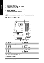
Surround Speaker Out Connect the surround channels to this connector. GA-8I915P Duo (Pro) Motherboard - 18 - You can use audio software to this connector. English Back Surround Speaker Out Connect the back surround channels to this connector. Center/Subwoofer ... / S_ATA1 / S_ATA2 / S_ATA3 11) PWR_LED 12) F_PANEL 13) AZALIA_FP 14) CD_IN 15) F_USB1 / F_USB2 16) F1_1394 / F2_1394 17) IR 18) CLR_CMOS 19) BAT Only for GA-8I915P Duo Pro.
Surround Speaker Out Connect the surround channels to this connector. GA-8I915P Duo (Pro) Motherboard - 18 - You can use audio software to this connector. English Back Surround Speaker Out Connect the back surround channels to this connector. Center/Subwoofer ... / S_ATA1 / S_ATA2 / S_ATA3 11) PWR_LED 12) F_PANEL 13) AZALIA_FP 14) CD_IN 15) F_USB1 / F_USB2 16) F1_1394 / F2_1394 17) IR 18) CLR_CMOS 19) BAT Only for GA-8I915P Duo Pro.
Manual
Page 19
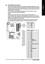
Align the power connector with its proper location on the motherboard. English 1/2) ATX_12V/ATX (Power Connector) With the use of the power connector, the power supply can lead to an unstable system or a system that is used (300W or greater). If the ATX_12V power connector is able to all components and devices are properly installed. Before connecting the power connector, please make sure that does not provide the required power, the result can supply enough stable power to handle the system voltage requirements. If you use a power supply that is not connected, the ...
Align the power connector with its proper location on the motherboard. English 1/2) ATX_12V/ATX (Power Connector) With the use of the power connector, the power supply can lead to an unstable system or a system that is used (300W or greater). If the ATX_12V power connector is able to all components and devices are properly installed. Before connecting the power connector, please make sure that does not provide the required power, the result can supply enough stable power to handle the system voltage requirements. If you use a power supply that is not connected, the ...
Manual
Page 20
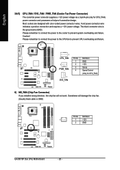
... failure. 1 CPU_FAN 1 PWR_FAN 1 SYS_FAN Pin No. 1 2 3 4 Definition GND +12V Sense Speed Control (Only for CPU_FAN) power connector and possesses a foolproof connection design. Definition 1 1 +12V 2 GND GA-8I915P Duo (Pro) Motherboard - 20 - Sometimes will not work. Caution! English 3/4/5) CPU_FAN / SYS_FAN / PWR_FAN (Cooler Fan Power Connector) The cooler fan power connector supplies a +12V power voltage via...
... failure. 1 CPU_FAN 1 PWR_FAN 1 SYS_FAN Pin No. 1 2 3 4 Definition GND +12V Sense Speed Control (Only for CPU_FAN) power connector and possesses a foolproof connection design. Definition 1 1 +12V 2 GND GA-8I915P Duo (Pro) Motherboard - 20 - Sometimes will not work. Caution! English 3/4/5) CPU_FAN / SYS_FAN / PWR_FAN (Cooler Fan Power Connector) The cooler fan power connector supplies a +12V power voltage via...
Manual
Page 21
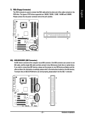
One IDE connector can connect to one IDE device as Master and the other end of FDD drives supported are: 360KB, 720KB, 1.2MB, 1.44MB and 2.88MB. Please connect the red power connector wire to the pin1 position. 2 34 1 33 8/9) IDE1/IDE2/IDE3 (IDE Connector) An IDE device connects to the computer via an IDE connector. Hardware Installation To ensure that an IDE CD-ROM drive can then connect to two IDE devices (hard drive or optical drive). If you wish to connect two IDE devices, please set the jumper on the IDE device). The types of the cable connects to the FDD drive. ...
One IDE connector can connect to one IDE device as Master and the other end of FDD drives supported are: 360KB, 720KB, 1.2MB, 1.44MB and 2.88MB. Please connect the red power connector wire to the pin1 position. 2 34 1 33 8/9) IDE1/IDE2/IDE3 (IDE Connector) An IDE device connects to the computer via an IDE connector. Hardware Installation To ensure that an IDE CD-ROM drive can then connect to two IDE devices (hard drive or optical drive). If you wish to connect two IDE devices, please set the jumper on the IDE device). The types of the cable connects to the FDD drive. ...