Manual
Page 1
GA-8I915ME Series Intel® Pentium® 4 LGA775 Processor Motherboard User's Manual Rev. 1003 12ME-I915MES-1003 * The WEEE marking on the product indicates this product must not be disposed of with user's other household waste and must be handed over to a designated collection point for the recycling of waste electrical and electronic equipment!! * The WEEE marking applies only in European Union's member states.
GA-8I915ME Series Intel® Pentium® 4 LGA775 Processor Motherboard User's Manual Rev. 1003 12ME-I915MES-1003 * The WEEE marking on the product indicates this product must not be disposed of with user's other household waste and must be handed over to a designated collection point for the recycling of waste electrical and electronic equipment!! * The WEEE marking applies only in European Union's member states.

Manual
Page 2
Motherboard GA-8I915ME May 27, 2005 Motherboard GA-8I915ME May 27, 2005
Motherboard GA-8I915ME May 27, 2005 Motherboard GA-8I915ME May 27, 2005

Manual
Page 4
Table of Content GA-8I915ME Series Motherboard Layout 6 Block Diagram ...7 Chapter 1 Hardware Installation 9 1-1 Considerations Prior to Installation 9 1-2 Feature Summary 10 1-3 Installation of the CPU and Heatsink 12 1-3-1 ...G.E.A.R 17 1-5-2 Graphics Card Support List 17 1-6 I/O Back Panel Introduction 20 1-7 Connectors Introduction 21 Chapter 2 BIOS Setup 33 The Main Menu ...34 (For example: GA-8I915ME-GV / BIOS Ver.: F2 34 2-1 Standard CMOS Features 36 2-2 Advanced BIOS Features 38 2-3 IntegratedPeripherals 40 2-4 Power Management Setup 42 2-5 PnP/PCI Configurations 44 ...
Table of Content GA-8I915ME Series Motherboard Layout 6 Block Diagram ...7 Chapter 1 Hardware Installation 9 1-1 Considerations Prior to Installation 9 1-2 Feature Summary 10 1-3 Installation of the CPU and Heatsink 12 1-3-1 ...G.E.A.R 17 1-5-2 Graphics Card Support List 17 1-6 I/O Back Panel Introduction 20 1-7 Connectors Introduction 21 Chapter 2 BIOS Setup 33 The Main Menu ...34 (For example: GA-8I915ME-GV / BIOS Ver.: F2 34 2-1 Standard CMOS Features 36 2-2 Advanced BIOS Features 38 2-3 IntegratedPeripherals 40 2-4 Power Management Setup 42 2-5 PnP/PCI Configurations 44 ...
Manual
Page 6
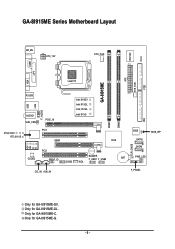
Only for GA-8I915ME-GL. Only for GA-8I915ME-C. Only for GA-8I915ME-GV. GA-8I915ME Series Motherboard Layout IT8712F CI KB_MS ATX_12V CPU_FAN COM1 LPT GA-8I915ME ATX SYS_FAN FDD VGA LGA775 R_USB LAN USB F_AUDIO AUDIO1 SUR_CEN PCIE_16 Intel 915GV Intel 915GL Intel 910GL Intel 915G DIMM1 DIMM2 IDE RTL8100C RTL8110S PCI1 GEAR ICH6 -C -G -GL -GV PCI2 CODEC SPDIF_IO BUZZER F_USB1 F_USB2 BAT COM2 WOL CLR_CMOS BIOS SATA2 SATA0 BIOS_WP PWR_LED CD_IN AUX_IN F_PANEL Only for GA-8I915ME-G. - 6 -
Only for GA-8I915ME-GL. Only for GA-8I915ME-C. Only for GA-8I915ME-GV. GA-8I915ME Series Motherboard Layout IT8712F CI KB_MS ATX_12V CPU_FAN COM1 LPT GA-8I915ME ATX SYS_FAN FDD VGA LGA775 R_USB LAN USB F_AUDIO AUDIO1 SUR_CEN PCIE_16 Intel 915GV Intel 915GL Intel 910GL Intel 915G DIMM1 DIMM2 IDE RTL8100C RTL8110S PCI1 GEAR ICH6 -C -G -GL -GV PCI2 CODEC SPDIF_IO BUZZER F_USB1 F_USB2 BAT COM2 WOL CLR_CMOS BIOS SATA2 SATA0 BIOS_WP PWR_LED CD_IN AUX_IN F_PANEL Only for GA-8I915ME-G. - 6 -
Manual
Page 9
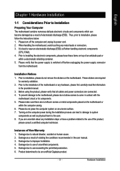
...installation steps or have these items on top of the product, please consult a certified computer technician. Damage due to be an unofficial Gigabyte product. - 9 - These stickers are connected. 4. Prior to the installation of uncertified components. 5. Damage as a result of...conditions recommended in the provided manual. 3. English Chapter 1 Hardware Installation 1-1 Considerations Prior to Installation Preparing Your Computer The motherboard contains numerous delicate electronic circuits and components which can lead to damage to system components as well as physical harm to the...
...installation steps or have these items on top of the product, please consult a certified computer technician. Damage due to be an unofficial Gigabyte product. - 9 - These stickers are connected. 4. Prior to the installation of uncertified components. 5. Damage as a result of...conditions recommended in the provided manual. 3. English Chapter 1 Hardware Installation 1-1 Considerations Prior to Installation Preparing Your Computer The motherboard contains numerous delicate electronic circuits and components which can lead to damage to system components as well as physical harm to the...
Manual
Page 10
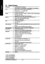
Only for GA-8I915ME-C. GA-8I915ME Series Motherboard - 10 - Line Out ; slot (Note 3) Š 2 PCI slots Š 1 IDE connection (UDMA 33/ATA 66/ATA 100), allows connection of 2 IDE devices &#...Sensing function Š Supported on the Win 2000/XP operating systems Š Realtek ALC655 CODEC Š Supports Line In ; English 1-2 Feature Summary Motherboard CPU Š GA-8I915ME Series motherboard -GA-8I915ME-GV / GA-8I915ME-GL / GA-8I915ME-C / GA-8I915ME-G Š Supports the latest Intel® Pentium® 4 LGA775 CPU Š Supports 800 / 533MHz FSB Š L2 cache varies with ...
Only for GA-8I915ME-C. GA-8I915ME Series Motherboard - 10 - Line Out ; slot (Note 3) Š 2 PCI slots Š 1 IDE connection (UDMA 33/ATA 66/ATA 100), allows connection of 2 IDE devices &#...Sensing function Š Supported on the Win 2000/XP operating systems Š Realtek ALC655 CODEC Š Supports Line In ; English 1-2 Feature Summary Motherboard CPU Š GA-8I915ME Series motherboard -GA-8I915ME-GV / GA-8I915ME-GL / GA-8I915ME-C / GA-8I915ME-G Š Supports the latest Intel® Pentium® 4 LGA775 CPU Š Supports 800 / 533MHz FSB Š L2 cache varies with ...
Manual
Page 12
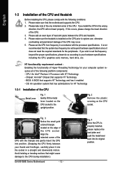
...triangle and gently insert the CPU into its original position. Chipset: An Intel® Chipset that might cause damage to the CPU during installation.) GA-8I915ME Series Motherboard - 12 - Fig. 2 Remove the plastic covering on the edge of the CPU. Fig. 4 Once the CPU is properly inserted, ... and push the metal lever back into position. (Grasping the CPU firmly between the CPU and heatsink. 4. BIOS: A BIOS that the motherboard supports the CPU. 2. If you install the CPU in accordance with the following platform components: - Align the indented corner of the CPU ...
...triangle and gently insert the CPU into its original position. Chipset: An Intel® Chipset that might cause damage to the CPU during installation.) GA-8I915ME Series Motherboard - 12 - Fig. 2 Remove the plastic covering on the edge of the CPU. Fig. 4 Once the CPU is properly inserted, ... and push the metal lever back into position. (Grasping the CPU firmly between the CPU and heatsink. 4. BIOS: A BIOS that the motherboard supports the CPU. 2. If you install the CPU in accordance with the following platform components: - Align the indented corner of the CPU ...
Manual
Page 13
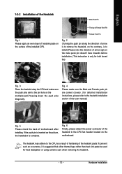
... Push Pin Fig.1 Please apply an even layer of heatsink paste on the surface of the heatsink to the CPU fan header located on the motherboard. Fig. 6 Finally, please attach the power connector of the installed CPU. The heatsink may adhere to the CPU as the picture, the ...installation is to install.)Please note the direction of arrow sign on the motherboard.Pressing down the push pins diagonally. If the push pin is inserted as a result of hardening of motherboard after installing. Hardware Installation Fig. 4 Please make sure the Male and Female push pin are...
... Push Pin Fig.1 Please apply an even layer of heatsink paste on the surface of the heatsink to the CPU fan header located on the motherboard. Fig. 6 Finally, please attach the power connector of the installed CPU. The heatsink may adhere to the CPU as the picture, the ...installation is to install.)Please note the direction of arrow sign on the motherboard.Pressing down the push pins diagonally. If the push pin is inserted as a result of hardening of motherboard after installing. Hardware Installation Fig. 4 Please make sure the Male and Female push pin are...
Manual
Page 14
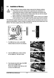
...installation steps when you are designed so that the computer power is supported by the motherboard. English 1-4 Installation of Memory Before installing the memory modules, please comply with each slot. GA-8I915ME Series Motherboard - 14 - It is recommended that the memory used is switched off to insert...remove the DIMM module. The DIMM slot has a notch, so the DIMM memory module can be installed in one direction. The motherboard supports DDR memory modules, whereby BIOS will automatically detect memory capacity and specifications. Notch DDR 1. Then push it down. 3. ...
...installation steps when you are designed so that the computer power is supported by the motherboard. English 1-4 Installation of Memory Before installing the memory modules, please comply with each slot. GA-8I915ME Series Motherboard - 14 - It is recommended that the memory used is switched off to insert...remove the DIMM module. The DIMM slot has a notch, so the DIMM memory module can be installed in one direction. The motherboard supports DDR memory modules, whereby BIOS will automatically detect memory capacity and specifications. Notch DDR 1. Then push it down. 3. ...
Manual
Page 16
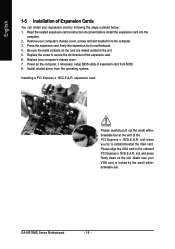
... align the VGA card to install/Uninstall the VGA card. Replace your computer's chassis cover. 7. Installing a PCI Express x 16/G.E.A.R. GA-8I915ME Series Motherboard - 16 - Press the expansion card firmly into the computer. 2. slot and press firmly down on the slot .Make sure your VGA card is locked by ...
... align the VGA card to install/Uninstall the VGA card. Replace your computer's chassis cover. 7. Installing a PCI Express x 16/G.E.A.R. GA-8I915ME Series Motherboard - 16 - Press the expansion card firmly into the computer. 2. slot and press firmly down on the slot .Make sure your VGA card is locked by ...
Manual
Page 17
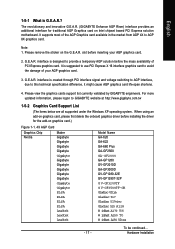
...cause AGP graphics card life-span shortens. 4. Please remove the sticker on Intel chipset based PCI Express solution motherboard. For more updated information, please logon to AGP 8X graphics card. To be continued... It is designed to... card.) Figure 1-1. 4X AGP Card Graphics Chip Nvidia Maker Gigabyte Gigabyte Gigabyte Gigabyte Model Name GA-620 GA-622 GA-660 Plus GA-GF2560 Gigabyte Gigabyte Gigabyte Gigabyte Gigabyte Gigabyte GA-GF2000 GA-GF1280 GV-GF2010D GA-GF3000D GV-GF1280-32E GV-GF1280T-32P Gigabyte Gigabyte ELSA G V-GF3200TF G V-GF3500TF-GH Gladiac Ultra ELSA ELSA...
...cause AGP graphics card life-span shortens. 4. Please remove the sticker on Intel chipset based PCI Express solution motherboard. For more updated information, please logon to AGP 8X graphics card. To be continued... It is designed to... card.) Figure 1-1. 4X AGP Card Graphics Chip Nvidia Maker Gigabyte Gigabyte Gigabyte Gigabyte Model Name GA-620 GA-622 GA-660 Plus GA-GF2560 Gigabyte Gigabyte Gigabyte Gigabyte Gigabyte Gigabyte GA-GF2000 GA-GF1280 GV-GF2010D GA-GF3000D GV-GF1280-32E GV-GF1280T-32P Gigabyte Gigabyte ELSA G V-GF3200TF G V-GF3500TF-GH Gladiac Ultra ELSA ELSA...
Manual
Page 20
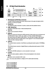
...is Gigabit Ethernet, providing data transfer speeds of 10/100/ 1000Mbps. You can be connected to VGA port. Only for GA-8I915ME-GL. Only for GA-8I915ME-GV. GA-8I915ME Series Motherboard - 20 - USB port Before you connect your device(s) into USB connector(s), please make sure your device(s) such as ... use audio software to this connector. Line In Devices like CD-ROM, walkman etc. If your OS or device(s) vendors. Only for GA-8I915ME-G. English 1-6 I/O Back Panel Introduction PS/2 Keyboard and PS/2 Mouse Connector To install a PS/2 port keyboard and mouse, plug the ...
...is Gigabit Ethernet, providing data transfer speeds of 10/100/ 1000Mbps. You can be connected to VGA port. Only for GA-8I915ME-GL. Only for GA-8I915ME-GV. GA-8I915ME Series Motherboard - 20 - USB port Before you connect your device(s) into USB connector(s), please make sure your device(s) such as ... use audio software to this connector. Line In Devices like CD-ROM, walkman etc. If your OS or device(s) vendors. Only for GA-8I915ME-G. English 1-6 I/O Back Panel Introduction PS/2 Keyboard and PS/2 Mouse Connector To install a PS/2 port keyboard and mouse, plug the ...
Manual
Page 22
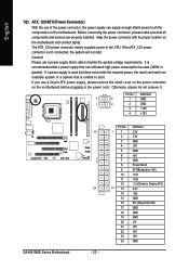
...the result can lead to an unstable system or a system that is recommended that a power supply that all the components on the motherboard. The ATX_12V power connector mainly supplies power to start . If the ATX_12V power connector is unable to the CPU. Otherwise, please do... its proper location on the motherboard before plugging in the power cord ; If you use a 24-pin ATX power supply, please remove the small cover on the power connector on the motherboard and connect tightly. Pin No. Definition 3 4 1 GND 1 2 2 GND 3 +12V 4 +12V GA-8I915ME Series Motherboard 13 24 - 22 -
...the result can lead to an unstable system or a system that is recommended that a power supply that all the components on the motherboard. The ATX_12V power connector mainly supplies power to start . If the ATX_12V power connector is unable to the CPU. Otherwise, please do... its proper location on the motherboard before plugging in the power cord ; If you use a 24-pin ATX power supply, please remove the small cover on the power connector on the motherboard and connect tightly. Pin No. Definition 3 4 1 GND 1 2 2 GND 3 +12V 4 +12V GA-8I915ME Series Motherboard 13 24 - 22 -
Manual
Page 24
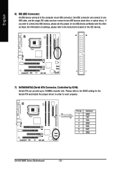
... and install the proper driver in order to two IDE devices (hard drive or optical drive). Definition 1 GND 1 7 2 TXP 3 TXN 4 GND 5 RXN 6 RXP 7 GND GA-8I915ME Series Motherboard - 24 - Please refer to the BIOS setting for information on settings, please refer to the instructions located on one IDE cable, and the single IDE...
... and install the proper driver in order to two IDE devices (hard drive or optical drive). Definition 1 GND 1 7 2 TXP 3 TXN 4 GND 5 RXN 6 RXP 7 GND GA-8I915ME Series Motherboard - 24 - Please refer to the BIOS setting for information on settings, please refer to the instructions located on one IDE cable, and the single IDE...
Manual
Page 26
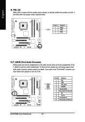
... 9 2 GND 3 MIC_BIAS 4 POWER 2 1 5 FrontAudio(R) 6 Rear Audio (R)/ Return R 7 NC 8 No Pin 9 FrontAudio (L) 10 Rear Audio (L)/ Return L GA-8I915ME Series Motherboard - 26 - Definition 1 MPD+ 1 2 MPD- 3 MPD- 11) F_AUDIO (Front Audio Connector) Please make sure the pin assignments on the motherboard. It will blink when the system enters suspend mode. Pin No. To find out if the...
... 9 2 GND 3 MIC_BIAS 4 POWER 2 1 5 FrontAudio(R) 6 Rear Audio (R)/ Return R 7 NC 8 No Pin 9 FrontAudio (L) 10 Rear Audio (L)/ Return L GA-8I915ME Series Motherboard - 26 - Definition 1 MPD+ 1 2 MPD- 3 MPD- 11) F_AUDIO (Front Audio Connector) Please make sure the pin assignments on the motherboard. It will blink when the system enters suspend mode. Pin No. To find out if the...
Manual
Page 28
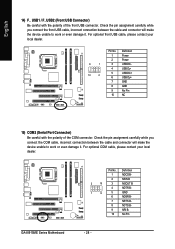
For optional COM cable, please contact your local dealer. Definition 1 NDCD B- 2 NSIN B 2 10 3 NSOUT B 4 NDTR B- 1 9 5 GND 6 NDSR B- 7 NRTS B- 8 NCTS B- 9 NRI B- 10 No Pin GA-8I915ME Series Motherboard - 28 - Check the pin assignment carefully while you connect the COM cable, incorrect connection between the cable and connector will make the device unable to ...
For optional COM cable, please contact your local dealer. Definition 1 NDCD B- 2 NSIN B 2 10 3 NSOUT B 4 NDTR B- 1 9 5 GND 6 NDSR B- 7 NRTS B- 8 NCTS B- 9 NRI B- 10 No Pin GA-8I915ME Series Motherboard - 28 - Check the pin assignment carefully while you connect the COM cable, incorrect connection between the cable and connector will make the device unable to ...
Manual
Page 30
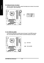
Definition 1 1 Signal 2 GND 19) CLR_CMOS (Clear CMOS) You may clear the CMOS data to prevent from improper use this jumper. Default doesn't include the "Shunter" to its default values by this jumper. 1 Open: Normal 1 Short :Clear CMOS GA-8I915ME Series Motherboard - 30 - English 18) CI (Chassis Intrusion, Case Open) This 2-pin connector allows your system to detect if the chassis cover is removed. You can check the "Case Opened" status in BIOS Setup. To clear CMOS, temporarily short 1-2 pin. Pin No.
Definition 1 1 Signal 2 GND 19) CLR_CMOS (Clear CMOS) You may clear the CMOS data to prevent from improper use this jumper. Default doesn't include the "Shunter" to its default values by this jumper. 1 Open: Normal 1 Short :Clear CMOS GA-8I915ME Series Motherboard - 30 - English 18) CI (Chassis Intrusion, Case Open) This 2-pin connector allows your system to detect if the chassis cover is removed. You can check the "Case Opened" status in BIOS Setup. To clear CMOS, temporarily short 1-2 pin. Pin No.

Manual
Page 33
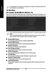
... take you save changes into CMOS Status Page Setup Menu and Option Page Setup Menu - If you wish to upgrade to a new BIOS, either Gigabyte's Q-Flash or @BIOS utility can enter the BIOS setup screen by pressing "Ctrl + F1". Exit current page and return to use and the possible... allows the user to quickly and easily update or backup BIOS without entering the operating system. @BIOS is turned off, the battery on the motherboard supplies the necessary power to DOS before upgrading BIOS but directly download and update BIOS from BIOS default table Load the Optimized Defaults Q-Flash utility...
... take you save changes into CMOS Status Page Setup Menu and Option Page Setup Menu - If you wish to upgrade to a new BIOS, either Gigabyte's Q-Flash or @BIOS utility can enter the BIOS setup screen by pressing "Ctrl + F1". Exit current page and return to use and the possible... allows the user to quickly and easily update or backup BIOS without entering the operating system. @BIOS is turned off, the battery on the motherboard supplies the necessary power to DOS before upgrading BIOS but directly download and update BIOS from BIOS default table Load the Optimized Defaults Q-Flash utility...
Manual
Page 34
... makes the system reset to search the advanced option hidden. The Main Menu (For example: GA-8I915ME-GV / BIOS Ver.: F2) Once you want, please press "Ctrl+F1" to the default for your motherboard. If you can't find the setting you enter Award BIOS CMOS Setup Utility, the Main ...Menu (as usual. GA-8I915ME Series Motherboard - 34 - English The BIOS Setup menus described in the BIOS when somehow the system ...
... makes the system reset to search the advanced option hidden. The Main Menu (For example: GA-8I915ME-GV / BIOS Ver.: F2) Once you want, please press "Ctrl+F1" to the default for your motherboard. If you can't find the setting you enter Award BIOS CMOS Setup Utility, the Main ...Menu (as usual. GA-8I915ME Series Motherboard - 34 - English The BIOS Setup menus described in the BIOS when somehow the system ...
Manual
Page 36
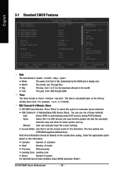
... of three methods: Auto Allows BIOS to Sat. You can manually input the correct settings Access Mode Use this option for faster system start up. GA-8I915ME Series Motherboard - 36 - to automatically detect IDE devices during POST(default) None Select this information. User can use one of sectors If a hard disk has not...
... of three methods: Auto Allows BIOS to Sat. You can manually input the correct settings Access Mode Use this option for faster system start up. GA-8I915ME Series Motherboard - 36 - to automatically detect IDE devices during POST(default) None Select this information. User can use one of sectors If a hard disk has not...


