Manual
Page 1
GA-8I915MD-G/ GA-8I915MD-GV Intel® Pentium® 4 LGA775 Processor Motherboard User's Manual Rev. 1003 12ME-8I915MDS-1003R
GA-8I915MD-G/ GA-8I915MD-GV Intel® Pentium® 4 LGA775 Processor Motherboard User's Manual Rev. 1003 12ME-8I915MDS-1003R

Manual
Page 2
Motherboard GA-8I915MD-G Sept. 1, 2005 Motherboard GA-8I915MD-G Sept. 1, 2005
Motherboard GA-8I915MD-G Sept. 1, 2005 Motherboard GA-8I915MD-G Sept. 1, 2005
Manual
Page 3
Motherboard GA-8I915MD-GV Sept. 1, 2005 Motherboard GA-8I915MD-GV Sept. 1, 2005
Motherboard GA-8I915MD-GV Sept. 1, 2005 Motherboard GA-8I915MD-GV Sept. 1, 2005
Manual
Page 5
Table of Contents GA-8I915MD-G / GA-8I915MD-GV Motherboard Layout 7 Block Diagram (GA-8I915MD-G 8 Block Diagram (GA-8I915MD-GV 9 Chapter 1 Hardware Installation 11 1-1 Considerations Prior to Installation 11 1-2 Feature Summary ... I/O Back Panel Introduction 20 1-7 Connectors Introduction 21 Chapter 2 BIOS Setup 31 The Main Menu (For example: BIOS Ver. : GA-8I915MD-G F3a 32 2-1 Standard CMOS Features 34 2-2 Advanced BIOS Features 36 2-3 IntegratedPeripherals 38 2-4 Power Management Setup 40 2-5 PnP/PCI ... & Exit Setup 47 2-12 Exit Without Saving 47 "*" Only for GA-8I915MD-GV. - 5 -
Table of Contents GA-8I915MD-G / GA-8I915MD-GV Motherboard Layout 7 Block Diagram (GA-8I915MD-G 8 Block Diagram (GA-8I915MD-GV 9 Chapter 1 Hardware Installation 11 1-1 Considerations Prior to Installation 11 1-2 Feature Summary ... I/O Back Panel Introduction 20 1-7 Connectors Introduction 21 Chapter 2 BIOS Setup 31 The Main Menu (For example: BIOS Ver. : GA-8I915MD-G F3a 32 2-1 Standard CMOS Features 34 2-2 Advanced BIOS Features 36 2-3 IntegratedPeripherals 38 2-4 Power Management Setup 40 2-5 PnP/PCI ... & Exit Setup 47 2-12 Exit Without Saving 47 "*" Only for GA-8I915MD-GV. - 5 -
Manual
Page 7
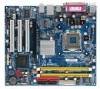
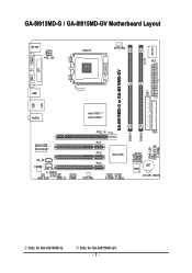
Only for GA-8I915MD-G. GA-8I915MD-G / GA-8I915MD-GV Motherboard Layout KB_MS ATX_12V LGA775 CPU_FAN ATX CI IDE1 IT8712 COMA GA-8I915MD-G or GA-8I915MD-GV LPT LAN VGA USB DDRII2 PWR_LED F_PANEL USB AUDIO Intel 915G / Intel 915GV PCIE_16 RTL8110S / RTL8100C CD_IN CODEC AUX_IN F_AUDIO SUR_CEN SPDIF_IO COMB PCI1 PCI2 Intel ICH6 PCI3 SYS_FAN F_USB1 F_USB2 DDRII1 FDD SATA1 SATA0 BIOS BAT CLR_CMOS Only for GA-8I915MD-GV. - 7 -
Only for GA-8I915MD-G. GA-8I915MD-G / GA-8I915MD-GV Motherboard Layout KB_MS ATX_12V LGA775 CPU_FAN ATX CI IDE1 IT8712 COMA GA-8I915MD-G or GA-8I915MD-GV LPT LAN VGA USB DDRII2 PWR_LED F_PANEL USB AUDIO Intel 915G / Intel 915GV PCIE_16 RTL8110S / RTL8100C CD_IN CODEC AUX_IN F_AUDIO SUR_CEN SPDIF_IO COMB PCI1 PCI2 Intel ICH6 PCI3 SYS_FAN F_USB1 F_USB2 DDRII1 FDD SATA1 SATA0 BIOS BAT CLR_CMOS Only for GA-8I915MD-GV. - 7 -
Manual
Page 8
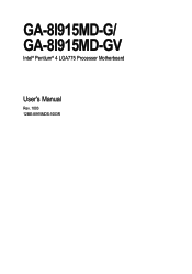
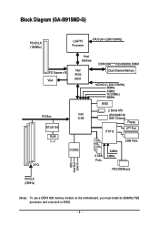
Block Diagram (GA-8I915MD-G) PCI-ECLK (100MHz) LGA775 Processor CPUCLK+/-(200/133MHz) PCI Express x16 VGA PCI Bus RTL8110S RJ45 Host Interface DDRII 600(Note)/533/400MHz DIMM Intel 915G MCH Dual Channel Memory MCHCLK (200/133MHz) 66MHz 33MHz 14.318MHz 48MHz BIOS 2 Serial ATA Intel ATA33/66/100 ICH6 IDE1 Channel Floppy IT8712 LPT Port COM Ports 3 PCI CODEC 8 USB Ports 24MHz 33MHz PS/2 KB/Mouse MIC Line-Out Line-In PCICLK (33MHz) (Note) To use a DDRII 600 memory module on the motherboard, you must install an 800MHz FSB processor and overclock in BIOS. - 8 -
Block Diagram (GA-8I915MD-G) PCI-ECLK (100MHz) LGA775 Processor CPUCLK+/-(200/133MHz) PCI Express x16 VGA PCI Bus RTL8110S RJ45 Host Interface DDRII 600(Note)/533/400MHz DIMM Intel 915G MCH Dual Channel Memory MCHCLK (200/133MHz) 66MHz 33MHz 14.318MHz 48MHz BIOS 2 Serial ATA Intel ATA33/66/100 ICH6 IDE1 Channel Floppy IT8712 LPT Port COM Ports 3 PCI CODEC 8 USB Ports 24MHz 33MHz PS/2 KB/Mouse MIC Line-Out Line-In PCICLK (33MHz) (Note) To use a DDRII 600 memory module on the motherboard, you must install an 800MHz FSB processor and overclock in BIOS. - 8 -
Manual
Page 9
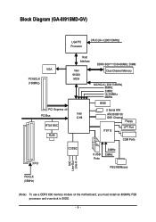
Block Diagram (GA-8I915MD-GV) LGA775 Processor CPUCLK+/-(200/133MHz) VGA PCI-ECLK (100MHz) PCI Express x4 PCI Bus RTL8100C RJ45 Host Interface Intel 915GV MCH DDRII 600(Note)533/400MHz DIMM Dual Channel Memory MCHCLK (200/133MHz) 66MHz 33MHz 14.318MHz 48MHz BIOS 2 Serial ATA Intel ATA33/66/100 ICH6 IDE1 Channel Floppy IT8712 LPT Port COM Ports 3 PCI CODEC 8 USB Ports 24MHz 33MHz PS/2 KB/Mouse MIC Line-Out Line-In PCICLK (33MHz) (Note) To use a DDRII 600 memory module on the motherboard, you must install an 800MHz FSB processor and overclock in BIOS. - 9 -
Block Diagram (GA-8I915MD-GV) LGA775 Processor CPUCLK+/-(200/133MHz) VGA PCI-ECLK (100MHz) PCI Express x4 PCI Bus RTL8100C RJ45 Host Interface Intel 915GV MCH DDRII 600(Note)533/400MHz DIMM Dual Channel Memory MCHCLK (200/133MHz) 66MHz 33MHz 14.318MHz 48MHz BIOS 2 Serial ATA Intel ATA33/66/100 ICH6 IDE1 Channel Floppy IT8712 LPT Port COM Ports 3 PCI CODEC 8 USB Ports 24MHz 33MHz PS/2 KB/Mouse MIC Line-Out Line-In PCICLK (33MHz) (Note) To use a DDRII 600 memory module on the motherboard, you must install an 800MHz FSB processor and overclock in BIOS. - 9 -
Manual
Page 11
... the information in the provided manual. 3. Before using the product, please verify that the power supply is best to be an unofficial Gigabyte product. - 11 - Turning on top of an antistatic pad or within the computer casing. 6. Thus, prior to the user....due to use of Non-Warranty 1. Hardware Installation English Chapter 1 Hardware Installation 1-1 Considerations Prior to Installation Preparing Your Computer The motherboard contains numerous delicate electronic circuits and components which can lead to damage to system components as well as physical harm to installation, ...
... the information in the provided manual. 3. Before using the product, please verify that the power supply is best to be an unofficial Gigabyte product. - 11 - Turning on top of an antistatic pad or within the computer casing. 6. Thus, prior to the user....due to use of Non-Warranty 1. Hardware Installation English Chapter 1 Hardware Installation 1-1 Considerations Prior to Installation Preparing Your Computer The motherboard contains numerous delicate electronic circuits and components which can lead to damage to system components as well as physical harm to installation, ...
Manual
Page 12
...; 2 DDR II DIMM memory slots (supports up to PCI Express x 4 mode (please refer to the VGA cards support list on page 18~19). Only for GA-8I915MD-G. GA-8I915MD-G/GA-8I915MD-GV Motherboard - 12 - MIC In Š Supports 2 / 4 / 6 channel audio Š SPDIF In/Out connection Š CD In connection Š AUX In connection Š IT8712 (Note 1) To use...
...; 2 DDR II DIMM memory slots (supports up to PCI Express x 4 mode (please refer to the VGA cards support list on page 18~19). Only for GA-8I915MD-G. GA-8I915MD-G/GA-8I915MD-GV Motherboard - 12 - MIC In Š Supports 2 / 4 / 6 channel audio Š SPDIF In/Out connection Š CD In connection Š AUX In connection Š IT8712 (Note 1) To use...
Manual
Page 13
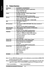
Hardware Installation English Hardware Monitor Š System voltage detection Š CPU temperature detection Š CPU / System fan speed detection Š CPU warning temperature Š CPU / System fan failure warning Š CPU smart fan control BIOS Š Use of licensed AWARD BIOS Š Supports Q-Flash Additional Features Š Supports @BIOS Š Supports EasyTune 5 (only supports Hardware Monitor function)(Note 3) Form Factor Š Micro ATX form factor; 24.4cm x 21.5cm (Note 3) EasyTune functions may vary depending on different motherboards. - 13 -
Hardware Installation English Hardware Monitor Š System voltage detection Š CPU temperature detection Š CPU / System fan speed detection Š CPU warning temperature Š CPU / System fan failure warning Š CPU smart fan control BIOS Š Use of licensed AWARD BIOS Š Supports Q-Flash Additional Features Š Supports @BIOS Š Supports EasyTune 5 (only supports Hardware Monitor function)(Note 3) Form Factor Š Micro ATX form factor; 24.4cm x 21.5cm (Note 3) EasyTune functions may vary depending on different motherboards. - 13 -
Manual
Page 14
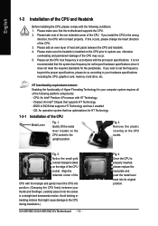
... all of the following conditions: 1. Fig. 2 Remove the plastic covering on the edge of the CPU socket. If you wish to the CPU during installation.) GA-8I915MD-G/GA-8I915MD-GV Motherboard - 14 - Avoid twisting or bending motions that supports HT Technology and has it into its original position. Please make sure the heatsink is properly inserted... colored triangle located on the CPU socket. Please take note of the one indented corner of the CPU. Chipset: An Intel® Chipset that the motherboard supports the CPU. 2.
... all of the following conditions: 1. Fig. 2 Remove the plastic covering on the edge of the CPU socket. If you wish to the CPU during installation.) GA-8I915MD-G/GA-8I915MD-GV Motherboard - 14 - Avoid twisting or bending motions that supports HT Technology and has it into its original position. Please make sure the heatsink is properly inserted... colored triangle located on the CPU socket. Please take note of the one indented corner of the CPU. Chipset: An Intel® Chipset that the motherboard supports the CPU. 2.
Manual
Page 15
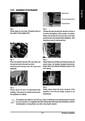
... removing the heatsink. - 15 - Hardware Installation Fig. 6 Finally, please attach the power connector of the heatsink to the pin hole on the motherboard.Pressing down the push pins diagonally. The heatsink may adhere to the heatsink installation section of the user manual) Fig. 5 Please check the back ...of motherboard after installing. Fig. 2 (Turning the push pin along the direction of arrow is to remove the heatsink, on the contrary, is to ...
... removing the heatsink. - 15 - Hardware Installation Fig. 6 Finally, please attach the power connector of the heatsink to the pin hole on the motherboard.Pressing down the push pins diagonally. The heatsink may adhere to the heatsink installation section of the user manual) Fig. 5 Please check the back ...of motherboard after installing. Fig. 2 (Turning the push pin along the direction of arrow is to remove the heatsink, on the contrary, is to ...
Manual
Page 16
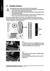
... will automatically detect memory capacity and specifications. Insert the DIMM memory module vertically into the DIMM socket. Then push it down. GA-8I915MD-G/GA-8I915MD-GV Motherboard - 16 - Memory modules have a foolproof insertion design. Memory modules are unable to prevent hardware damage. 3. Reverse the installation...lock the DIMM module. Please make sure that the computer power is recommended that the memory used is supported by the motherboard. English 1-4 Installation of Memory Before installing the memory modules, please comply with each slot. A memory module can be...
... will automatically detect memory capacity and specifications. Insert the DIMM memory module vertically into the DIMM socket. Then push it down. GA-8I915MD-G/GA-8I915MD-GV Motherboard - 16 - Memory modules have a foolproof insertion design. Memory modules are unable to prevent hardware damage. 3. Reverse the installation...lock the DIMM module. Please make sure that the computer power is recommended that the memory used is supported by the motherboard. English 1-4 Installation of Memory Before installing the memory modules, please comply with each slot. A memory module can be...
Manual
Page 18
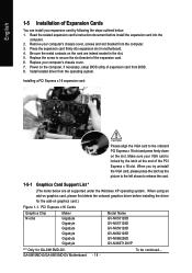
...Graphics Chip Nvidia Maker Gigabyte Gigabyte Gigabyte Gigabyte Gigabyte Gigabyte Model Name GV-NX53128D GV-NX57128D GV-NX59128D GV-NX62128D GV-NX66256D GV-NX66T128VP "*" Only for the add-on graphics card.) Figure 1-1. Read the related expansion card's instruction document before installing the driver for GA-8I915MD-GV. Install related driver...screws and slot bracket from the operating system. GA-8I915MD-G/GA-8I915MD-GV Motherboard - 18 - Make sure your VGA card is locked by following the steps outlined below are indeed seated in motherboard. 4. When using an add-on the card...
...Graphics Chip Nvidia Maker Gigabyte Gigabyte Gigabyte Gigabyte Gigabyte Gigabyte Model Name GV-NX53128D GV-NX57128D GV-NX59128D GV-NX62128D GV-NX66256D GV-NX66T128VP "*" Only for the add-on graphics card.) Figure 1-1. Read the related expansion card's instruction document before installing the driver for GA-8I915MD-GV. Install related driver...screws and slot bracket from the operating system. GA-8I915MD-G/GA-8I915MD-GV Motherboard - 18 - Make sure your VGA card is locked by following the steps outlined below are indeed seated in motherboard. 4. When using an add-on the card...
Manual
Page 20
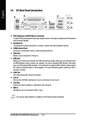
... processing devices. COMA (Serial Port) Connects to this connector. Also make sure your OS supports USB controller. Line In Devices like CD-ROM, walkman etc. GA-8I915MD-G/GA-8I915MD-GV Motherboard - 20 - MIC In Microphone can use audio software to configure 2-/4-/6-channel audio functioning. For more information please contact your OS does not support USB controller...
... processing devices. COMA (Serial Port) Connects to this connector. Also make sure your OS supports USB controller. Line In Devices like CD-ROM, walkman etc. GA-8I915MD-G/GA-8I915MD-GV Motherboard - 20 - MIC In Microphone can use audio software to configure 2-/4-/6-channel audio functioning. For more information please contact your OS does not support USB controller...
Manual
Page 22
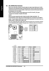
...(Onlyfor24-pinATX) 23 +5V (Only for 24-pin ATX) 1 13 12 3.3V(Onlyfor24-pinATX) 24 GND(Only for 24-pin ATX) GA-8I915MD-G/GA-8I915MD-GV Motherboard - 22 - Definition Pin No. If the ATX_12V power connector is recommended that a power supply that can withstand high power consumption be used ... power connector mainly supplies power to all components and devices are properly installed. Caution! Align the power connector with its proper location on the motherboard before plugging in the power cord ; Otherwise, please do not remove it. 42 31 Pin No. 1 2 3 4 Definition GND GND...
...(Onlyfor24-pinATX) 23 +5V (Only for 24-pin ATX) 1 13 12 3.3V(Onlyfor24-pinATX) 24 GND(Only for 24-pin ATX) GA-8I915MD-G/GA-8I915MD-GV Motherboard - 22 - Definition Pin No. If the ATX_12V power connector is recommended that a power supply that can withstand high power consumption be used ... power connector mainly supplies power to all components and devices are properly installed. Caution! Align the power connector with its proper location on the motherboard before plugging in the power cord ; Otherwise, please do not remove it. 42 31 Pin No. 1 2 3 4 Definition GND GND...
Manual
Page 24
... device). 40 39 2 1 7) SATA0/SATA1 (SATA Connector) SATA can then connect to 150MB/s transfer rate. Pin No. Definition 1 GND 2 TXP 3 TXN 4 GND 1 7 5 RXN 6 RXP 7 GND GA-8I915MD-G/GA-8I915MD-GV Motherboard - 24 - One IDE connector can connect to one IDE device as Master and the other as Slave (for the Serial ATA and install the proper...
... device). 40 39 2 1 7) SATA0/SATA1 (SATA Connector) SATA can then connect to 150MB/s transfer rate. Pin No. Definition 1 GND 2 TXP 3 TXN 4 GND 1 7 5 RXN 6 RXP 7 GND GA-8I915MD-G/GA-8I915MD-GV Motherboard - 24 - One IDE connector can connect to one IDE device as Master and the other as Slave (for the Serial ATA and install the proper...
Manual
Page 26
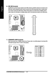
... Switch) (Red) MSG(Message LED/Power/Sleep LED) (Yellow) NC ( Purple) Pin 1: LED anode(+) Pin 2: LED cathode(-) Pin 1: Power Pin 2- Definition 1 CD-L 1 2 GND 3 GND 4 CD-R GA-8I915MD-G/GA-8I915MD-GV Motherboard - 26 - Pin 3: NC Pin 4: Data(-) Open: Normal Close: Reset Hardware System Open: Normal Close: Power On/Off Pin 1: LED anode(+) Pin 2: LED cathode(-) NC 11...
... Switch) (Red) MSG(Message LED/Power/Sleep LED) (Yellow) NC ( Purple) Pin 1: LED anode(+) Pin 2: LED cathode(-) Pin 1: Power Pin 2- Definition 1 CD-L 1 2 GND 3 GND 4 CD-R GA-8I915MD-G/GA-8I915MD-GV Motherboard - 26 - Pin 3: NC Pin 4: Data(-) Open: Normal Close: Reset Hardware System Open: Normal Close: Power On/Off Pin 1: LED anode(+) Pin 2: LED cathode(-) NC 11...
Manual
Page 28
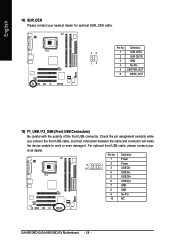
Definition 1 Power 9 1 2 Power 10 2 3 USB DX- 4 USB Dy- 5 USB DX+ 6 USB Dy+ 7 GND 8 GND 9 No Pin 10 NC GA-8I915MD-G/GA-8I915MD-GV Motherboard - 28 - Pin No. Check the pin assignment carefully while you connect the front USB cable, incorrect connection between the cable and connector will make the ...
Definition 1 Power 9 1 2 Power 10 2 3 USB DX- 4 USB Dy- 5 USB DX+ 6 USB Dy+ 7 GND 8 GND 9 No Pin 10 NC GA-8I915MD-G/GA-8I915MD-GV Motherboard - 28 - Pin No. Check the pin assignment carefully while you connect the front USB cable, incorrect connection between the cable and connector will make the ...

Manual
Page 30
Dispose of explosion if battery is incorrectly replaced. Re-install the battery. 4. Take out the battery gently and put it aside for one minute). 3. GA-8I915MD-G/GA-8I915MD-GV Motherboard - 30 - If you can use this jumper. To clear CMOS, temporarily short 1-2 pin. Plug the power cord and turn ON the computer. English 18) CLR_CMOS (...
Dispose of explosion if battery is incorrectly replaced. Re-install the battery. 4. Take out the battery gently and put it aside for one minute). 3. GA-8I915MD-G/GA-8I915MD-GV Motherboard - 30 - If you can use this jumper. To clear CMOS, temporarily short 1-2 pin. Plug the power cord and turn ON the computer. English 18) CLR_CMOS (...


