Manual
Page 1
GA-8I865G775-G / GA-8I865G775-G-RH Intel® Pentium® 4 LGA775 Processor Motherboard User's Manual Rev. 2002 12ME-8I865GTG-2002R * The WEEE marking on the product indicates this product must not be disposed of with user's other household waste and must be handed over to a designated collection point for the recycling of waste electrical and electronic equipment!! * The WEEE marking applies only in European Union's member states.
GA-8I865G775-G / GA-8I865G775-G-RH Intel® Pentium® 4 LGA775 Processor Motherboard User's Manual Rev. 2002 12ME-8I865GTG-2002R * The WEEE marking on the product indicates this product must not be disposed of with user's other household waste and must be handed over to a designated collection point for the recycling of waste electrical and electronic equipment!! * The WEEE marking applies only in European Union's member states.

Manual
Page 2
Motherboard GA-8I865G775-G Apr. 18, 2006 Motherboard GA-8I865G775-G Apr. 18, 2006
Motherboard GA-8I865G775-G Apr. 18, 2006 Motherboard GA-8I865G775-G Apr. 18, 2006

Manual
Page 5
Table of Contents ItemChecklist ...7 OptionalAccessories ...7 GA-8I865G775-G(-RH) Motherboard Layout 8 Block Diagram ...9 Chapter 1 Hardware Installation 11 1-1 Considerations Prior to Installation 11 1-2 Feature Summary 12 1-3 Installation of the CPU and Heatsink 14 1-3-1 Installation of the ...
Table of Contents ItemChecklist ...7 OptionalAccessories ...7 GA-8I865G775-G(-RH) Motherboard Layout 8 Block Diagram ...9 Chapter 1 Hardware Installation 11 1-1 Considerations Prior to Installation 11 1-2 Feature Summary 12 1-3 Installation of the CPU and Heatsink 14 1-3-1 Installation of the ...

Manual
Page 8
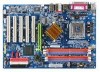
GA-8I865G775-G(-RH) Motherboard Layout KB_MS LGA775 ATX_12V CPU_FAN COMA LPT GA-8I865G775 -G(-RH) DDR1 VGA ATX R_USB USB_LAN AUDIO F_AUDIO Intel 865G DDR4 DDR3 DDR2 AGP Marvell 8001 CODEC CD_IN SUR_CEN IT8712 AUX_IN CI COMB SPDIF_O PCI1 ICH5 PCI2 IDE1 IDE2 BAT CLR_CMOS FDD PCI3 SATA0 PCI4 BIOS SATA1 PCI5 SYS _FAN F_USB1 F_USB2 F_PANEL PWR_LED - 8 -
GA-8I865G775-G(-RH) Motherboard Layout KB_MS LGA775 ATX_12V CPU_FAN COMA LPT GA-8I865G775 -G(-RH) DDR1 VGA ATX R_USB USB_LAN AUDIO F_AUDIO Intel 865G DDR4 DDR3 DDR2 AGP Marvell 8001 CODEC CD_IN SUR_CEN IT8712 AUX_IN CI COMB SPDIF_O PCI1 ICH5 PCI2 IDE1 IDE2 BAT CLR_CMOS FDD PCI3 SATA0 PCI4 BIOS SATA1 PCI5 SYS _FAN F_USB1 F_USB2 F_PANEL PWR_LED - 8 -

Manual
Page 11
... sure there are connected. 4. Damage due to be an unofficial Gigabyte product. - 11 - Damage as a result of the motherboard or any hardware, please first carefully read the information in contact with the motherboard circuit or its power cord. 2. Damage due to use exceeding... (ESD) cuff when handling electronic components (CPU, RAM). 4. Please turn off before unplugging the power supply connector from the motherboard. Turning on top of the product, please consult a certified computer technician. Thus, prior to improper installation. 4. Prior to installing...
... sure there are connected. 4. Damage due to be an unofficial Gigabyte product. - 11 - Damage as a result of the motherboard or any hardware, please first carefully read the information in contact with the motherboard circuit or its power cord. 2. Damage due to use exceeding... (ESD) cuff when handling electronic components (CPU, RAM). 4. Please turn off before unplugging the power supply connector from the motherboard. Turning on top of the product, please consult a certified computer technician. Thus, prior to improper installation. 4. Prior to installing...

Manual
Page 12
... connector Š 1 AUX In connector Š 1 Surround Center connector Š 1 SPDIF Out connector Š 1 power LED connector Š 2 USB 2.0/1.1 connectors for additional 4 ports by cables GA-8I865G775-G(-RH) Motherboard - 12 -
... connector Š 1 AUX In connector Š 1 Surround Center connector Š 1 SPDIF Out connector Š 1 power LED connector Š 2 USB 2.0/1.1 connectors for additional 4 ports by cables GA-8I865G775-G(-RH) Motherboard - 12 -

Manual
Page 13
... Internet Security (OEM version) Form Factor Š ATX form factor; 30.5cm x 21cm (Note 1) For further CPU support information, please go to GIGABYTE's website. (Note 2) Due to standard PC architecture, a certain amount of memory size will instead be shown as 3.xxGB memory during system startup. (...Note 3) EasyTune functions may vary depending on different motherboards. - 13 - For example, 4 GB of memory is reserved for system usage and therefore the actual memory size is less than the stated...
... Internet Security (OEM version) Form Factor Š ATX form factor; 30.5cm x 21cm (Note 1) For further CPU support information, please go to GIGABYTE's website. (Note 2) Due to standard PC architecture, a certain amount of memory size will instead be shown as 3.xxGB memory during system startup. (...Note 3) EasyTune functions may vary depending on different motherboards. - 13 - For example, 4 GB of memory is reserved for system usage and therefore the actual memory size is less than the stated...
Manual
Page 14
...of Hyper-Threading Technology for your computer system requires all of the following conditions: 1. Chipset: An Intel® Chipset that the motherboard supports the CPU. 2. Avoid twisting or bending motions that supports HT Technology and has it into its original position. If you ...that has optimizations for the peripherals. Please set beyond the proper specifications, please do so according to the CPU during installation.) GA-8I865G775-G(-RH) Motherboard - 14 - OS: An operation system that the system bus frequency be set the CPU host frequency in the wrong direction,...
...of Hyper-Threading Technology for your computer system requires all of the following conditions: 1. Chipset: An Intel® Chipset that the motherboard supports the CPU. 2. Avoid twisting or bending motions that supports HT Technology and has it into its original position. If you ...that has optimizations for the peripherals. Please set beyond the proper specifications, please do so according to the CPU during installation.) GA-8I865G775-G(-RH) Motherboard - 14 - OS: An operation system that the system bus frequency be set the CPU host frequency in the wrong direction,...

Manual
Page 15
... the heatsink paste.To prevent such an occurrence, it is inserted as a result of hardening of the heatsink to the pin hole on the motherboard.Pressing down the push pins diagonally. If the push pin is suggested that either thermal tape rather than heat sink paste be used for detailed... Fig. 5 Please check the back of the installed CPU. Fig. 4 Please make sure the push pins aim to the CPU fan header located on the motherboard. The heatsink may adhere to install.) Please note the direction of arrow sign on the male push pin doesn't face inwards before installation. (This instruction...
... the heatsink paste.To prevent such an occurrence, it is inserted as a result of hardening of the heatsink to the pin hole on the motherboard.Pressing down the push pins diagonally. If the push pin is suggested that either thermal tape rather than heat sink paste be used for detailed... Fig. 5 Please check the back of the installed CPU. Fig. 4 Please make sure the push pins aim to the CPU fan header located on the motherboard. The heatsink may adhere to install.) Please note the direction of arrow sign on the male push pin doesn't face inwards before installation. (This instruction...

Manual
Page 16
... edges of the DIMM sockets to prevent hardware damage. 3. If you wish to insert the module, please switch the direction. DDR memory module Fig. 1 Fig. 2 GA-8I865G775-G(-RH) Motherboard - 16 - Before installing or removing memory modules, please make sure that the computer power is supported by the... motherboard. The memory capacity used is switched off to lock the DIMM module. Then push it down. Memory modules have a foolproof insertion design. A memory module can ...
... edges of the DIMM sockets to prevent hardware damage. 3. If you wish to insert the module, please switch the direction. DDR memory module Fig. 1 Fig. 2 GA-8I865G775-G(-RH) Motherboard - 16 - Before installing or removing memory modules, please make sure that the computer power is supported by the... motherboard. The memory capacity used is switched off to lock the DIMM module. Then push it down. Memory modules have a foolproof insertion design. A memory module can ...

Manual
Page 17
... when you try to the onboard AGP slot and press firmly down on the slot. Hardware Installation Power on the card are indeed seated in motherboard. 4.
... when you try to the onboard AGP slot and press firmly down on the slot. Hardware Installation Power on the card are indeed seated in motherboard. 4.
Manual
Page 18
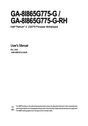
... connection. Line In Devices like mouses, modems, and etc. Line Out Connect the stereo speakers, earphone or front surround speakers to the lower port (purple). GA-8I865G775-G(-RH) Motherboard - 18 - VGA Port Monitor can be connected to Line In jack. have a standard USB interface. can be connected to Serial port. You can be...
... connection. Line In Devices like mouses, modems, and etc. Line Out Connect the stereo speakers, earphone or front surround speakers to the lower port (purple). GA-8I865G775-G(-RH) Motherboard - 18 - VGA Port Monitor can be connected to Line In jack. have a standard USB interface. can be connected to Serial port. You can be...

Manual
Page 20
... 6 +5V 7 GND 8 Power Good 9 5V SB (stand by +5V) 1 10 +12V 11 11 3.3V 12 -12V 13 GND 14 PS_ON(soft on the motherboard and connect tightly. Please use a power supply that is able to all components and devices are properly installed. English 1/2) ATX_12V/ATX (Power Connector) With the... to the CPU. Align the power connector with its proper location on /off) 15 GND 16 GND 17 GND 18 -5V 19 +5V 20 +5V GA-8I865G775-G(-RH) Motherboard - 20 - It is not connected, the system will not start . Otherwise, please do not remove it. 42 31 Pin No. 1 2 3 4 ...
... 6 +5V 7 GND 8 Power Good 9 5V SB (stand by +5V) 1 10 +12V 11 11 3.3V 12 -12V 13 GND 14 PS_ON(soft on the motherboard and connect tightly. Please use a power supply that is able to all components and devices are properly installed. English 1/2) ATX_12V/ATX (Power Connector) With the... to the CPU. Align the power connector with its proper location on /off) 15 GND 16 GND 17 GND 18 -5V 19 +5V 20 +5V GA-8I865G775-G(-RH) Motherboard - 20 - It is not connected, the system will not start . Otherwise, please do not remove it. 42 31 Pin No. 1 2 3 4 ...

Manual
Page 22
... FDD cable while the other end of FDD drives supported are: 360KB, 720KB, 1.2MB, 1.44MB and 2.88MB. Definition 1 GND 7 1 2 TXP 3 TXN 4 GND 5 RXN 6 RXP 7 GND GA-8I865G775-G(-RH) Motherboard - 22 - Before attaching the FDD cable, please take note of the foolproof groove in order to 150MB/s transfer rate.
... FDD cable while the other end of FDD drives supported are: 360KB, 720KB, 1.2MB, 1.44MB and 2.88MB. Definition 1 GND 7 1 2 TXP 3 TXN 4 GND 5 RXN 6 RXP 7 GND GA-8I865G775-G(-RH) Motherboard - 22 - Before attaching the FDD cable, please take note of the foolproof groove in order to 150MB/s transfer rate.

Manual
Page 24
... mode. In order to play sound. Definition 1 MIC 2 GND 1 2 3 MIC_BIAS 4 POWER 9 10 5 FrontAudio(R) 6 Rear Audio (R)/ Return R 7 NC 8 No Pin 9 FrontAudio (L) 10 Rear Audio (L)/ Return L GA-8I865G775-G(-RH) Motherboard - 24 - To find out if the chassis you are the same as the pin assigments on /off. Definition 1 MPD+ 1 2 MPD- 3 MPD- 10) F_AUDIO (Front Audio...
... mode. In order to play sound. Definition 1 MIC 2 GND 1 2 3 MIC_BIAS 4 POWER 9 10 5 FrontAudio(R) 6 Rear Audio (R)/ Return R 7 NC 8 No Pin 9 FrontAudio (L) 10 Rear Audio (L)/ Return L GA-8I865G775-G(-RH) Motherboard - 24 - To find out if the chassis you are the same as the pin assigments on /off. Definition 1 MPD+ 1 2 MPD- 3 MPD- 10) F_AUDIO (Front Audio...

Manual
Page 26
For optional SPDIFO cable, please contact your stereo system has digital input function. Definition 1 Power 1 2 SPDIFO 3 GND GA-8I865G775-G(-RH) Motherboard - 26 - English 13) SUR_CEN Please contact your nearest dealer for optional SUR_CEN cable. 16 25 Pin No. 1 2 3 4 5 6 Definition SUR OUTL SUR OUTR GND No Pin ...
For optional SPDIFO cable, please contact your stereo system has digital input function. Definition 1 Power 1 2 SPDIFO 3 GND GA-8I865G775-G(-RH) Motherboard - 26 - English 13) SUR_CEN Please contact your nearest dealer for optional SUR_CEN cable. 16 25 Pin No. 1 2 3 4 5 6 Definition SUR OUTL SUR OUTR GND No Pin ...

Manual
Page 28
English 17) CI (Chassis Intrusion, Case Open) This 2-pin connector allows your system to its default values by this header. To clear CMOS, temporarily short the two pins. Default doesn't include the jumper to avoid improper use of this header. Open: Normal Short: Clear CMOS GA-8I865G775-G(-RH) Motherboard - 28 - You can check the "Case Opened" status in BIOS Setup. Definition 1 1 Signal 2 GND 18) CLR_CMOS (Clear CMOS) You may clear the CMOS data to detect if the chassis cover is removed. Pin No.
English 17) CI (Chassis Intrusion, Case Open) This 2-pin connector allows your system to its default values by this header. To clear CMOS, temporarily short the two pins. Default doesn't include the jumper to avoid improper use of this header. Open: Normal Short: Clear CMOS GA-8I865G775-G(-RH) Motherboard - 28 - You can check the "Case Opened" status in BIOS Setup. Definition 1 1 Signal 2 GND 18) CLR_CMOS (Clear CMOS) You may clear the CMOS data to detect if the chassis cover is removed. Pin No.

Manual
Page 31
... the CMOS changes, only for the first time, it with caution and avoid inadequate operation that BIOS needs to be reset to a new BIOS, either GIGABYTE's Q-Flash or @BIOS utility can enter the BIOS setup screen by pressing "Ctrl + F1". Q-Flash allows the user to quickly and easily update or... CMOS value from CMOS, only for the highlighted item. Because BIOS flashing is potentially risky, please do it is displayed at the bottom of the motherboard. You can be used. CONTROL KEYS Enter> Move to the CMOS SRAM. When the power is turned off, the battery on -line description of...
... the CMOS changes, only for the first time, it with caution and avoid inadequate operation that BIOS needs to be reset to a new BIOS, either GIGABYTE's Q-Flash or @BIOS utility can enter the BIOS setup screen by pressing "Ctrl + F1". Q-Flash allows the user to quickly and easily update or... CMOS value from CMOS, only for the highlighted item. Because BIOS flashing is potentially risky, please do it is displayed at the bottom of the motherboard. You can be used. CONTROL KEYS Enter> Move to the CMOS SRAM. When the power is turned off, the battery on -line description of...

Manual
Page 32
GA-8I865G775-G D7 . . . . :BIOS Setup/Q-Flash, : Xpress Recovery2, For Boot Menu 02/22/2006-i865G-6A79AG0VC-00 ...) Once you want, please press "Ctrl+F1" to search the advanced option hidden. Press to the default for stability. GA-8I865G775-G(-RH) Motherboard - 32 - English : For Boot Menu Select boot sequence for onboard (or add-on the screen. Please Load Optimized...system reset to exit this chapter are for reference only and may differ from the exact settings for your motherboard. If you can't find the setting you enter Award BIOS CMOS Setup Utility, the Main Menu (as ...
GA-8I865G775-G D7 . . . . :BIOS Setup/Q-Flash, : Xpress Recovery2, For Boot Menu 02/22/2006-i865G-6A79AG0VC-00 ...) Once you want, please press "Ctrl+F1" to search the advanced option hidden. Press to the default for stability. GA-8I865G775-G(-RH) Motherboard - 32 - English : For Boot Menu Select boot sequence for onboard (or add-on the screen. Please Load Optimized...system reset to exit this chapter are for reference only and may differ from the exact settings for your motherboard. If you can't find the setting you enter Award BIOS CMOS Setup Utility, the Main Menu (as ...

Manual
Page 34
..." to select this to automatically detect IDE devices during POST. (Default value) • None Select this if no IDE devices are : Large/Auto(default:Auto) GA-8I865G775-G(-RH) Motherboard - 34 - IDE Channel 0 Master/Slave ; For example, 1 p.m. The four options are used and the system will skip the automatic detection step and allow for...
..." to select this to automatically detect IDE devices during POST. (Default value) • None Select this if no IDE devices are : Large/Auto(default:Auto) GA-8I865G775-G(-RH) Motherboard - 34 - IDE Channel 0 Master/Slave ; For example, 1 p.m. The four options are used and the system will skip the automatic detection step and allow for...


