Manual
Page 1
GA-890FXA-UD7 AM3 socket motherboard for AMD Phenom™ II processor/ AMD Athlon™ II processor User's Manual Rev. 2001 12ME-890FXA7-2001R
GA-890FXA-UD7 AM3 socket motherboard for AMD Phenom™ II processor/ AMD Athlon™ II processor User's Manual Rev. 2001 12ME-890FXA7-2001R
Manual
Page 2
Motherboard GA-890FXA-UD7 Mar. 29, 2010 Motherboard GA-890FXA-UD7 Mar. 29, 2010
Motherboard GA-890FXA-UD7 Mar. 29, 2010 Motherboard GA-890FXA-UD7 Mar. 29, 2010
Manual
Page 3
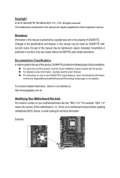
... read or download the information on/from the Support&Downloads\Motherboard\Technology Guide page on your motherboard revision before updating motherboard BIOS, drivers, or when looking for technical information. For product-related information, check on our website at: http://www.gigabyte.com.tw Identifying Your Motherboard Revision The revision number on our website. Copyright ©...
... read or download the information on/from the Support&Downloads\Motherboard\Technology Guide page on your motherboard revision before updating motherboard BIOS, drivers, or when looking for technical information. For product-related information, check on our website at: http://www.gigabyte.com.tw Identifying Your Motherboard Revision The revision number on our website. Copyright ©...
Manual
Page 4
Table of Contents Box Contents...6 Optional Items...6 GA-890FXA-UD7 Motherboard Layout 7 GA-890FXA-UD7 Motherboard Block Diagram 8 Chapter 1 Hardware Installation 9 1-1 Installation Precautions 9 1-2 Product Specifications 10 1-3 Installing the CPU and CPU Cooler 13 1-3-1 Installing the CPU 13 1-3-2 Installing the CPU Cooler ...
Table of Contents Box Contents...6 Optional Items...6 GA-890FXA-UD7 Motherboard Layout 7 GA-890FXA-UD7 Motherboard Block Diagram 8 Chapter 1 Hardware Installation 9 1-1 Installation Precautions 9 1-2 Product Specifications 10 1-3 Installing the CPU and CPU Cooler 13 1-3-1 Installing the CPU 13 1-3-2 Installing the CPU Cooler ...
Manual
Page 6
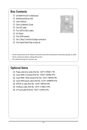
...PDIF In cable (Part No. 12CR1-1SPDIN-0*R) COM port cable (Part No. 12CF1-1CM001-3*R) LPT port cable (Part No. 12CF1-1LP001-0*R) - 6 - Box Contents GA-890FXA-UD7 motherboard Motherboard driver disk User's Manual Quick Installation Guide One IDE cable Four SATA 3Gb/s cables I/O Shield One SATA bracket Two 2-Way CrossFireX bridge connectors One Hybrid... Silent-Pipe module kit • The box contents above are subject to change without notice. • The motherboard image is for reference only and the actual items shall depend on the product package you obtain.
...PDIF In cable (Part No. 12CR1-1SPDIN-0*R) COM port cable (Part No. 12CF1-1CM001-3*R) LPT port cable (Part No. 12CF1-1LP001-0*R) - 6 - Box Contents GA-890FXA-UD7 motherboard Motherboard driver disk User's Manual Quick Installation Guide One IDE cable Four SATA 3Gb/s cables I/O Shield One SATA bracket Two 2-Way CrossFireX bridge connectors One Hybrid... Silent-Pipe module kit • The box contents above are subject to change without notice. • The motherboard image is for reference only and the actual items shall depend on the product package you obtain.
Manual
Page 7
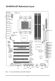
... DDR3_4 ATX PW_SW RST_SW PWR_FAN IDE FDD GIGABYTE SATA2 CMOS_SW AMD SB850 M_BIOS B_BIOS GSATA2_6 GSATA2_7 SATA3_4 SATA3_5 SATA3_2 SATA3_3 SATA3_0 SATA3_1 TSR1(Note) BAT TSL1(Note) SYS_FAN2 F_USB3 F_USB1 SYS_FAN1 CLR_CMOS LPT F_1394 F_USB2 F_PANEL (Note ) For error code information, please refer to Chapter 5. - 7 - GA-890FXA-UD7 Motherboard Layout KB_MS_USB ATX_12V RCA_SPDIF USB_1394_ESATA_2 USB_1394_ESATA_1...
... DDR3_4 ATX PW_SW RST_SW PWR_FAN IDE FDD GIGABYTE SATA2 CMOS_SW AMD SB850 M_BIOS B_BIOS GSATA2_6 GSATA2_7 SATA3_4 SATA3_5 SATA3_2 SATA3_3 SATA3_0 SATA3_1 TSR1(Note) BAT TSL1(Note) SYS_FAN2 F_USB3 F_USB1 SYS_FAN1 CLR_CMOS LPT F_1394 F_USB2 F_PANEL (Note ) For error code information, please refer to Chapter 5. - 7 - GA-890FXA-UD7 Motherboard Layout KB_MS_USB ATX_12V RCA_SPDIF USB_1394_ESATA_2 USB_1394_ESATA_1...
Manual
Page 8
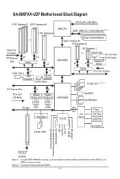
... install two memory modules and install them in the DDR3_3 and DDR3_4 memory sockets. (Note 2) Two share the same ports with eSATA. - 8 - GA-890FXA-UD7 Motherboard Block Diagram 4 PCI Express x8 2 PCI Express x16 1 PCI Express x4 or PCIe CLK (100 MHz) PCI Express x8 x16 Bus Switch x4 x1... Dual Channel Memory Hyper Transport 3.0 1 PCI Express x4 AMD 890FX 1 PCI Express x1 or 2 SATA 3Gb/s ATA-133/100/66/ 33 IDE Channel GIGABYTE x4 x1 SATA2 Switch PCIe CLK (100 MHz) 14 USB 2.0/1.1 (Note 2) PCI Express Bus x1 x1 PCIe CLK (100 MHz) Realtek Realtek RTL8111D RTL8111D...
... install two memory modules and install them in the DDR3_3 and DDR3_4 memory sockets. (Note 2) Two share the same ports with eSATA. - 8 - GA-890FXA-UD7 Motherboard Block Diagram 4 PCI Express x8 2 PCI Express x16 1 PCI Express x4 or PCIe CLK (100 MHz) PCI Express x8 x16 Bus Switch x4 x1... Dual Channel Memory Hyper Transport 3.0 1 PCI Express x4 AMD 890FX 1 PCI Express x1 or 2 SATA 3Gb/s ATA-133/100/66/ 33 IDE Channel GIGABYTE x4 x1 SATA2 Switch PCIe CLK (100 MHz) 14 USB 2.0/1.1 (Note 2) PCI Express Bus x1 x1 PCIe CLK (100 MHz) Realtek Realtek RTL8111D RTL8111D...

Manual
Page 9
... within an electrostatic shielding container. • Before unplugging the power supply cable from the power outlet before installing or removing the motherboard or other hardware components. • When connecting hardware components to the internal connectors on the computer power during the installation process... system on an uneven surface. • Do not place the computer system in a high-temperature environment. • Turning on the motherboard, make sure the power supply voltage has been set according to the local voltage standard. • Before using the product, please verify...
... within an electrostatic shielding container. • Before unplugging the power supply cable from the power outlet before installing or removing the motherboard or other hardware components. • When connecting hardware components to the internal connectors on the computer power during the installation process... system on an uneven surface. • Do not place the computer system in a high-temperature environment. • Turning on the motherboard, make sure the power supply voltage has been set according to the local voltage standard. • Before using the product, please verify...
Manual
Page 12
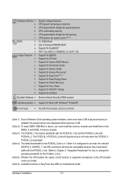
... control function is supported will depend on the CPU/system cooler you must install two memory modules and install them in EasyTune may differ by motherboard model. Hardware Monitor w w w w w w BIOS w w w w Unique Features w w w w w w w w w w w w Bundled Software w System voltage detection CPU/system temperature detection CPU/system/North Bridge fan speed detection CPU overheating warning...
... control function is supported will depend on the CPU/system cooler you must install two memory modules and install them in EasyTune may differ by motherboard model. Hardware Monitor w w w w w w BIOS w w w w Unique Features w w w w w w w w w w w w Bundled Software w System voltage detection CPU/system temperature detection CPU/system/North Bridge fan speed detection CPU overheating warning...
Manual
Page 13
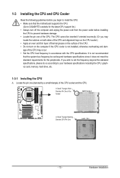
... socket.) • Apply an even and thin layer of thermal grease on the computer if the CPU cooler is not recommended that the motherboard supports the CPU. (Go to GIGABYTE's website for the peripherals. age of the CPU socket and the CPU. Locate the pin one of the CPU. The CPU cannot...
... socket.) • Apply an even and thin layer of thermal grease on the computer if the CPU cooler is not recommended that the motherboard supports the CPU. (Go to GIGABYTE's website for the peripherals. age of the CPU socket and the CPU. Locate the pin one of the CPU. The CPU cannot...

Manual
Page 14
... on the CPU socket and gently insert the CPU into the fully locked position. Follow the steps below to correctly install the CPU into the motherboard CPU socket. • Before installing the CPU, make sure to turn off the computer and unplug the power cord from the power outlet to prevent...
... on the CPU socket and gently insert the CPU into the fully locked position. Follow the steps below to correctly install the CPU into the motherboard CPU socket. • Before installing the CPU, make sure to turn off the computer and unplug the power cord from the power outlet to prevent...

Manual
Page 15
1-3-2 Installing the CPU Cooler Follow the steps below to correctly install the CPU cooler on the CPU. (The following procedure uses the GIGABYTE cooler as the picture above shows) to lock into place. (Refer to the CPU. Step 4: Turn the cam handle from the left side to the ....) Step 1: Apply an even and thin layer of thermal grease on the surface of the CPU cooler to the CPU fan header (CPU_FAN) on the motherboard. Inadequately removing the CPU cooler may adhere to your CPU cooler installation manual for instructions on the retention frame. Hardware Installation Step 2: Place the CPU...
1-3-2 Installing the CPU Cooler Follow the steps below to correctly install the CPU cooler on the CPU. (The following procedure uses the GIGABYTE cooler as the picture above shows) to lock into place. (Refer to the CPU. Step 4: Turn the cam handle from the left side to the ....) Step 1: Apply an even and thin layer of thermal grease on the surface of the CPU cooler to the CPU fan header (CPU_FAN) on the motherboard. Inadequately removing the CPU cooler may adhere to your CPU cooler installation manual for instructions on the retention frame. Hardware Installation Step 2: Place the CPU...

Manual
Page 16
... to install the Hybrid Silent-Pipe module: If you want to connect the front audio module from your chassis to the F_AUDIO connector on the motherboard, be sure to connect it before installing the Hybrid Silent-Pipe module to install the Hybrid Silent-Pipe module: Step 1: Unfasten the diagonally placed screws...
... to install the Hybrid Silent-Pipe module: If you want to connect the front audio module from your chassis to the F_AUDIO connector on the motherboard, be sure to connect it before installing the Hybrid Silent-Pipe module to install the Hybrid Silent-Pipe module: Step 1: Unfasten the diagonally placed screws...
Manual
Page 17
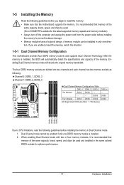
...Enabling Dual Channel memory mode will automatically detect the specifications and capacity of the same capacity, brand, speed, and chips be used . (Go to GIGABYTE's website for optimum performance. - 17 - 1-5 Installing the Memory Read the following : Channel 0: DDR3_1, DDR3_3 Channel 1: DDR3_2, DDR3_4 Dual Channel...Sided, DS=Double-Sided, "- -"=No Memory) DDR3_1 DDR3_2 DDR3_3 DDR3_4 Due to install the memory: • Make sure that the motherboard supports the memory. It is installed, the BIOS will double the original memory bandwidth. If you are divided into two channels and each...
...Enabling Dual Channel memory mode will automatically detect the specifications and capacity of the same capacity, brand, speed, and chips be used . (Go to GIGABYTE's website for optimum performance. - 17 - 1-5 Installing the Memory Read the following : Channel 0: DDR3_1, DDR3_3 Channel 1: DDR3_2, DDR3_4 Dual Channel...Sided, DS=Double-Sided, "- -"=No Memory) DDR3_1 DDR3_2 DDR3_3 DDR3_4 Due to install the memory: • Make sure that the motherboard supports the memory. It is installed, the BIOS will double the original memory bandwidth. If you are divided into two channels and each...

Manual
Page 18
Follow the steps below to install DDR3 DIMMs on this motherboard. Spread the retaining clips at both ends of the memory module. Step 1: Note the orientation of the memory socket. Place the memory module on the ...
Follow the steps below to install DDR3 DIMMs on this motherboard. Spread the retaining clips at both ends of the memory module. Step 1: Note the orientation of the memory socket. Place the memory module on the ...
Manual
Page 19
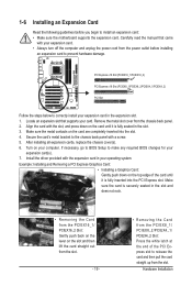
... turn off the computer and unplug the power cord from the power outlet before you begin to install an expansion card: • Make sure the motherboard supports the expansion card. 1-6 Installing an Expansion Card Read the following guidelines before installing an expansion card to prevent hardware damage. PCI Express x16 Slot...
... turn off the computer and unplug the power cord from the power outlet before you begin to install an expansion card: • Make sure the motherboard supports the expansion card. 1-6 Installing an Expansion Card Read the following guidelines before installing an expansion card to prevent hardware damage. PCI Express x16 Slot...
Manual
Page 20
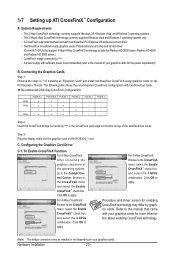
... the display cable into the graphics card on top of the two/three/four cards. Procedure and driver screen for the power requirement) B. A CrossFireX-supported motherboard with two/three/four cards. a PCIEX16_2 a a a a PCIEX8_1 -a a a PCIEX8_2 --a a PCIEX4_1 - - - - - To Enable CrossFireX Function For 2-Way CrossFireX: After installing the graphics card driver in "1-6 Installing an...
... the display cable into the graphics card on top of the two/three/four cards. Procedure and driver screen for the power requirement) B. A CrossFireX-supported motherboard with two/three/four cards. a PCIEX16_2 a a a a PCIEX8_1 -a a a PCIEX8_2 --a a PCIEX4_1 - - - - - To Enable CrossFireX Function For 2-Way CrossFireX: After installing the graphics card driver in "1-6 Installing an...

Manual
Page 21
... secure the SATA bracket to the chassis back panel with a screw. Step 3: Connect the power cable from the bracket to the SATA port on your motherboard. Then attach the SATA power cable to hardware. • Insert the SATA signal cable and SATA power cable securely into the external SATA connector on...
... secure the SATA bracket to the chassis back panel with a screw. Step 3: Connect the power cable from the bracket to the SATA port on your motherboard. Then attach the SATA power cable to hardware. • Insert the SATA signal cable and SATA power cable securely into the external SATA connector on...

Manual
Page 22
... The IEEE 1394 port supports the IEEE 1394a specification, featuring high speed, high bandwidth and hotplug capabilities. Do not rock it straight out from the motherboard. • When removing the cable, pull it side to side to 1 Gbps data rate. Use this feature, ensure that your audio system provides a coaxial digital...
... The IEEE 1394 port supports the IEEE 1394a specification, featuring high speed, high bandwidth and hotplug capabilities. Do not rock it straight out from the motherboard. • When removing the cable, pull it side to side to 1 Gbps data rate. Use this feature, ensure that your audio system provides a coaxial digital...

Manual
Page 24
.../F_USB3 17) F_1394 18) LPT 19) CLR_CMOS 20) COM 21) BAT 22) PW_SW 23) RST_SW 24) CMOS_SW Read the following guidelines before turning on the motherboard. Hardware Installation - 24 -
.../F_USB3 17) F_1394 18) LPT 19) CLR_CMOS 20) COM 21) BAT 22) PW_SW 23) RST_SW 24) CMOS_SW Read the following guidelines before turning on the motherboard. Hardware Installation - 24 -


