Manual
Page 1
GA-890FXA-UD7 AM3 socket motherboard for AMD Phenom™ II processor/ AMD Athlon™ II processor User's Manual Rev. 2001 12ME-890FXA7-2001R
GA-890FXA-UD7 AM3 socket motherboard for AMD Phenom™ II processor/ AMD Athlon™ II processor User's Manual Rev. 2001 12ME-890FXA7-2001R
Manual
Page 3
... on how to their respective owners. Disclaimer Information in this manual may be made by copyright laws and is the property of the motherboard is protected by GIGABYTE without GIGABYTE's prior written permission. For product-related information, check on our... example, "REV: 1.0" means the revision of GIGABYTE. For instructions on our website. All rights reserved. Example: Documentation Classifications In order to assist in this manual may be reproduced, copied, translated, transmitted, or published in this manual is 1.0. Copyright © 2010 GIGA-BYTE TECHNOLOGY...
... on how to their respective owners. Disclaimer Information in this manual may be made by copyright laws and is the property of the motherboard is protected by GIGABYTE without GIGABYTE's prior written permission. For product-related information, check on our... example, "REV: 1.0" means the revision of GIGABYTE. For instructions on our website. All rights reserved. Example: Documentation Classifications In order to assist in this manual may be reproduced, copied, translated, transmitted, or published in this manual is 1.0. Copyright © 2010 GIGA-BYTE TECHNOLOGY...
Manual
Page 5
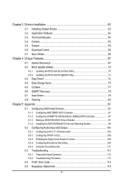
Chapter 3 Drivers Installation 63 3-1 Installing Chipset Drivers 63 3-2 Application Software 64 3-3 Technical Manuals 64 3-4 Contact...65 3-5 System...65 3-6 Download Center 66 3-7 New Utilities...66 Chapter 4 Unique Features 67 4-1 Xpress Recovery2 67 ... 4-7 Auto Green...79 4-8 Teaming ...80 Chapter 5 Appendix...81 5-1 Configuring SATA Hard Drive(s 81 5-1-1 Configuring AMD SB850 SATA Controller 81 5-1-2 Configuring GIGABYTE SATA2/JMicron JMB362 SATA Controller 87 5-1-3 Making a SATA RAID/AHCI Driver Diskette 93 5-1-4 Installing the SATA RAID/AHCI Driver and Operating System 95 5-2 ...
Chapter 3 Drivers Installation 63 3-1 Installing Chipset Drivers 63 3-2 Application Software 64 3-3 Technical Manuals 64 3-4 Contact...65 3-5 System...65 3-6 Download Center 66 3-7 New Utilities...66 Chapter 4 Unique Features 67 4-1 Xpress Recovery2 67 ... 4-7 Auto Green...79 4-8 Teaming ...80 Chapter 5 Appendix...81 5-1 Configuring SATA Hard Drive(s 81 5-1-1 Configuring AMD SB850 SATA Controller 81 5-1-2 Configuring GIGABYTE SATA2/JMicron JMB362 SATA Controller 87 5-1-3 Making a SATA RAID/AHCI Driver Diskette 93 5-1-4 Installing the SATA RAID/AHCI Driver and Operating System 95 5-2 ...
Manual
Page 6
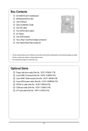
Box Contents GA-890FXA-UD7 motherboard Motherboard driver disk User's Manual Quick Installation Guide One IDE cable Four SATA 3Gb/s cables I/O Shield One SATA bracket Two 2-Way CrossFireX bridge connectors One Hybrid Silent-Pipe module kit &#...
Box Contents GA-890FXA-UD7 motherboard Motherboard driver disk User's Manual Quick Installation Guide One IDE cable Four SATA 3Gb/s cables I/O Shield One SATA bracket Two 2-Way CrossFireX bridge connectors One Hybrid Silent-Pipe module kit &#...

Manual
Page 9
Prior to installation, carefully read the user's manual and follow these procedures: • Prior to installation, do not remove or break motherboard S/N (Serial Number) sticker or warranty sticker provided by unplugging the power ...
Prior to installation, carefully read the user's manual and follow these procedures: • Prior to installation, do not remove or break motherboard S/N (Serial Number) sticker or warranty sticker provided by unplugging the power ...

Manual
Page 15
... the steps below to correctly install the CPU cooler on the CPU. (The following procedure uses the GIGABYTE cooler as the picture above shows) to lock into place. (Refer to your CPU cooler installation manual for instructions on installing the cooler.) Step 5: Finally, attach the power connector of the retention frame. Step...
... the steps below to correctly install the CPU cooler on the CPU. (The following procedure uses the GIGABYTE cooler as the picture above shows) to lock into place. (Refer to your CPU cooler installation manual for instructions on installing the cooler.) Step 5: Finally, attach the power connector of the retention frame. Step...
Manual
Page 19
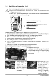
... the slot. If necessary, go to BIOS Setup to correctly install your expansion card(s). 7. Install the driver provided with your operating system. Carefully read the manual that supports your computer. Locate an expansion slot that came with the expansion card in the expansion slot. 1. Remove the metal slot cover from the...
... the slot. If necessary, go to BIOS Setup to correctly install your expansion card(s). 7. Install the driver provided with your operating system. Carefully read the manual that supports your computer. Locate an expansion slot that came with the expansion card in the expansion slot. 1. Remove the metal slot cover from the...
Manual
Page 20
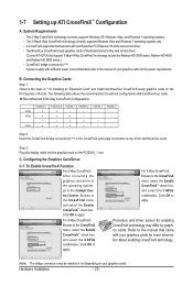
...cards of identical brand and chip and correct driver (Current ATI GPUs that came with sufficient power is recommended (refer to the manual of the two/three/four cards. Step 2: Insert the CrossFireX bridge connector(s)(Note) in "1-6 Installing an Expansion Card" and ...check box. Browse to apply. To Enable CrossFireX Function For 2-Way CrossFireX: After installing the graphics card driver in the operating system, go to the manual that support 3-Way/4-Way CrossFireX technology include the Radeon HD 3800 series, Radeon HD 4800 and Radeon HD 5800 series.) - a PCIEX16_2 a a a a...
...cards of identical brand and chip and correct driver (Current ATI GPUs that came with sufficient power is recommended (refer to the manual of the two/three/four cards. Step 2: Insert the CrossFireX bridge connector(s)(Note) in "1-6 Installing an Expansion Card" and ...check box. Browse to apply. To Enable CrossFireX Function For 2-Way CrossFireX: After installing the graphics card driver in the operating system, go to the manual that support 3-Way/4-Way CrossFireX technology include the Radeon HD 3800 series, Radeon HD 4800 and Radeon HD 5800 series.) - a PCIEX16_2 a a a a...

Manual
Page 31
... 1 - 31 - For purchasing the optional S/PDIF In cable, please contact the local dealer. For information about connecting the S/PDIF digital audio cable, carefully read the manual for digital audio output from your graphics card if you wish to connect an HDMI display to an audio device that supports digital audio out...
... 1 - 31 - For purchasing the optional S/PDIF In cable, please contact the local dealer. For information about connecting the S/PDIF digital audio cable, carefully read the manual for digital audio output from your graphics card if you wish to connect an HDMI display to an audio device that supports digital audio out...
Manual
Page 33
... do so may cause damage to the motherboard. • After system restart, go to BIOS Setup to load factory defaults (select Load Optimized Defaults) or manually configure the BIOS settings (refer to Chapter 2, "BIOS Setup," for a few seconds.
... do so may cause damage to the motherboard. • After system restart, go to BIOS Setup to load factory defaults (select Load Optimized Defaults) or manually configure the BIOS settings (refer to Chapter 2, "BIOS Setup," for a few seconds.
Manual
Page 35
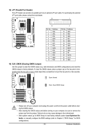
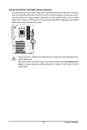
... the power outlet before clearing the CMOS values. • After system restart, go to BIOS Setup to load factory defaults (select Load Optimized Defaults) or manually configure the BIOS settings (refer to Chapter 2, "BIOS Setup," for BIOS configurations). - 35 - The power button and reset button allow users to quickly turn off...
... the power outlet before clearing the CMOS values. • After system restart, go to BIOS Setup to load factory defaults (select Load Optimized Defaults) or manually configure the BIOS settings (refer to Chapter 2, "BIOS Setup," for BIOS configurations). - 35 - The power button and reset button allow users to quickly turn off...
Manual
Page 42
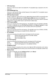
...the board to default values. Allows you to alter the North Bridge controller frequency for the installed CPU. PCIE Clock(MHz) Allows you to manually set to Manual. Auto BIOS will automatically adjust the HT Link Frequency. (Default) x1~x10 Sets HT Link Frequency to x1~x10 (200 MHz~2.0 GHz)....automatically adjust the HT Link Width. (Default) 8 bit Sets HT Link Width to 8 bit. 16 bit Sets HT Link Width to 16 bit. Manual allows the CPU Frequency (MHz) item below to be configurable. (Default: Auto) Memory Clock This option is configurable only when Set Memory Clock is ...
...the board to default values. Allows you to alter the North Bridge controller frequency for the installed CPU. PCIE Clock(MHz) Allows you to manually set to Manual. Auto BIOS will automatically adjust the HT Link Frequency. (Default) x1~x10 Sets HT Link Frequency to x1~x10 (200 MHz~2.0 GHz)....automatically adjust the HT Link Width. (Default) 8 bit Sets HT Link Width to 8 bit. 16 bit Sets HT Link Width to 16 bit. Manual allows the CPU Frequency (MHz) item below to be configurable. (Default: Auto) Memory Clock This option is configurable only when Set Memory Clock is ...

Manual
Page 44
... under the same items on the MB Intelligent Tweaker(M.I.T.) main menu. Unganged Sets memory control mode to two single-channel. (Default) DDR3 Timing Items Manual allows all DDR3 Timing items below to set memory control mode. Trfc2 for DIMM1 Options are : Auto (default), 90ns, 110ns, 160ns, 300ns, 350ns...Time Options are : Auto (default), 90ns, 110ns, 160ns, 300ns, 350ns. Options are : Auto (default), 5T~12T. Row Precharge Time Options are : Auto (default), Manual. Minimum RAS Active Time Options are: Auto (default), 15T~30T. 1T/2T Command Timing Options are: Auto (default), 1T, 2T.
... under the same items on the MB Intelligent Tweaker(M.I.T.) main menu. Unganged Sets memory control mode to two single-channel. (Default) DDR3 Timing Items Manual allows all DDR3 Timing items below to set memory control mode. Trfc2 for DIMM1 Options are : Auto (default), 90ns, 110ns, 160ns, 300ns, 350ns...Time Options are : Auto (default), 90ns, 110ns, 160ns, 300ns, 350ns. Options are : Auto (default), 5T~12T. Row Precharge Time Options are : Auto (default), Manual. Minimum RAS Active Time Options are: Auto (default), 15T~30T. 1T/2T Command Timing Options are: Auto (default), 1T, 2T.

Manual
Page 46
...950V ~ 1.450V The adjustable range is dependent on the CPU being installed. (Default: Normal) Note: Increasing CPU voltage may result in damage to manually set the system voltages as required. (Default) 1.050V ~ 1.460V The adjustable range is from 1.210V to the memory or reduce the useful ...2.410V The adjustable range is from 0.950V to set memory voltage. The adjustable range is from 2.220V to set the North Bridge voltage. Manual allows all voltage control items below to be configurable. (Default: Auto) CPU PLL Voltage Control Allows you to set the CPU North Bridge ...
...950V ~ 1.450V The adjustable range is dependent on the CPU being installed. (Default: Normal) Note: Increasing CPU voltage may result in damage to manually set the system voltages as required. (Default) 1.050V ~ 1.460V The adjustable range is from 1.210V to the memory or reduce the useful ...2.410V The adjustable range is from 0.950V to set memory voltage. The adjustable range is from 2.220V to set the North Bridge voltage. Manual allows all voltage control items below to be configurable. (Default: Auto) CPU PLL Voltage Control Allows you to set the CPU North Bridge ...

Manual
Page 48
...-Detection Press to autodetect the parameters of floppy disk drive installed in your system. Precomp Write precompensation cylinder. If you wish to enter the parameters manually, refer to the information on this item to select the type of the IDE/SATA device on the hard drive. Options are determined by using...
...-Detection Press to autodetect the parameters of floppy disk drive installed in your system. Precomp Write precompensation cylinder. If you wish to enter the parameters manually, refer to the information on this item to select the type of the IDE/SATA device on the hard drive. Options are determined by using...
Manual
Page 49
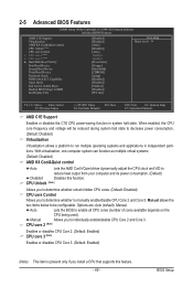
...heat output from your computer and its power consumption. (Default) Disabled Disables this feature. - 49 - Options are: Auto (default), Manual. 2-5 Advanced BIOS Features CMOS Setup Utility-Copyright (C) 1984-2010 Award Software Advanced BIOS Features AMD C1E Support Virtualization AMD K8 Cool&...to determine whether to run multiple operating systems and applications in system halt state. Manual allows the two items below to individually enable/disable CPU Core 2 and Core 3. Manual Allows you install a CPU that supports this function. Capability Away Mode Full Screen ...
...heat output from your computer and its power consumption. (Default) Disabled Disables this feature. - 49 - Options are: Auto (default), Manual. 2-5 Advanced BIOS Features CMOS Setup Utility-Copyright (C) 1984-2010 Award Software Advanced BIOS Features AMD C1E Support Virtualization AMD K8 Cool&...to determine whether to run multiple operating systems and applications in system halt state. Manual allows the two items below to individually enable/disable CPU Core 2 and Core 3. Manual Allows you install a CPU that supports this function. Capability Away Mode Full Screen ...
Manual
Page 63
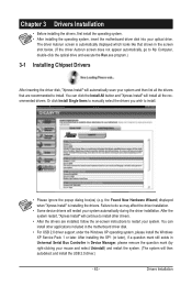
.... • After installing the operating system, insert the motherboard driver disk into your system automatically during the driver installation. Or click Install Single Items to manually select the drivers you wish to do so may affect the driver installation. • Some device drivers will then autodetect and install the USB 2.0 driver...
.... • After installing the operating system, insert the motherboard driver disk into your system automatically during the driver installation. Or click Install Single Items to manually select the drivers you wish to do so may affect the driver installation. • Some device drivers will then autodetect and install the USB 2.0 driver...

Manual
Page 64
You can click the Install button on the right of an item to install it. 3-3 Technical Manuals This page provides GIGABYTE's application guides, content descriptions for this driver disk, and the motherboard manuals. Drivers Installation - 64 - 3-2 Application Software This page displays all the utilities and applications that GIGABYTE develops and some free software.
You can click the Install button on the right of an item to install it. 3-3 Technical Manuals This page provides GIGABYTE's application guides, content descriptions for this driver disk, and the motherboard manuals. Drivers Installation - 64 - 3-2 Application Software This page displays all the utilities and applications that GIGABYTE develops and some free software.
Manual
Page 70
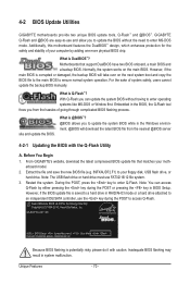
...please do it with the Q-Flash Utility A. GIGABYTE Q-Flash and @BIOS are easy-to-use and allow you to your moth- With Q-Flash you from the nearest @BIOS server 4-2-1 Updating the BIOS with caution. During the POST, press the key to enter MS-DOS mode. GA-890FXA-UD7 DC . . . . : BIOS Setup...this motherboard features the DualBIOS™ design, which enhances protection for the safety and stability of system safety, users cannot update the backup BIOS manually. However, if the main BIOS is saved to a hard drive in RAID/AHCI mode or a hard drive attached to access Q-Flash. ...
...please do it with the Q-Flash Utility A. GIGABYTE Q-Flash and @BIOS are easy-to-use and allow you to your moth- With Q-Flash you from the nearest @BIOS server 4-2-1 Updating the BIOS with caution. During the POST, press the key to enter MS-DOS mode. GA-890FXA-UD7 DC . . . . : BIOS Setup...this motherboard features the DualBIOS™ design, which enhances protection for the safety and stability of system safety, users cannot update the backup BIOS manually. However, if the main BIOS is saved to a hard drive in RAID/AHCI mode or a hard drive attached to access Q-Flash. ...

Manual
Page 73
... a BIOS update. 2. Follow the on -screen instructions to complete. C. Update the BIOS Using the Internet Update Function: Click Update BIOS from GIGABYTE Server, select the @BIOS server site closest to your location and then download the BIOS file that the BIOS file to be flashed matches your... system after the system restarts. During the BIOS update process, ensure the Internet connection is not present on the @BIOS server site, please manually download the BIOS update file from File, then select the location where you save the current BIOS file. 4. If the BIOS update file...
... a BIOS update. 2. Follow the on -screen instructions to complete. C. Update the BIOS Using the Internet Update Function: Click Update BIOS from GIGABYTE Server, select the @BIOS server site closest to your location and then download the BIOS file that the BIOS file to be flashed matches your... system after the system restarts. During the BIOS update process, ensure the Internet connection is not present on the @BIOS server site, please manually download the BIOS update file from File, then select the location where you save the current BIOS file. 4. If the BIOS update file...


