Manual
Page 1
GA-890FXA-UD5 AM3 socket motherboard for AMD Phenom™ II processor/ AMD Athlon™ II processor User's Manual Rev. 3001 12ME-890FXA5-3001R
GA-890FXA-UD5 AM3 socket motherboard for AMD Phenom™ II processor/ AMD Athlon™ II processor User's Manual Rev. 3001 12ME-890FXA5-3001R

Manual
Page 2
Motherboard GA-890FXA-UD5 Nov. 1, 2010 Motherboard GA-890FXA-UD5 Nov. 1, 2010
Motherboard GA-890FXA-UD5 Nov. 1, 2010 Motherboard GA-890FXA-UD5 Nov. 1, 2010

Manual
Page 3
... of this manual is protected by copyright laws and is 1.0. Example: No part of GIGABYTE. For product-related information, check on our website at: http://www.gigabyte.com Identifying Your Motherboard Revision The revision number on your motherboard revision before updating motherboard BIOS, drivers, or when looking for technical information. Changes to their respective owners...
... of this manual is protected by copyright laws and is 1.0. Example: No part of GIGABYTE. For product-related information, check on our website at: http://www.gigabyte.com Identifying Your Motherboard Revision The revision number on your motherboard revision before updating motherboard BIOS, drivers, or when looking for technical information. Changes to their respective owners...
Manual
Page 4
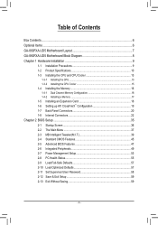
Table of Contents Box Contents...6 Optional Items...6 GA-890FXA-UD5 Motherboard Layout 7 GA-890FXA-UD5 Motherboard Block Diagram 8 Chapter 1 Hardware Installation 9 1-1 Installation Precautions 9 1-2 Product Specifications 10 1-3 Installing the CPU and CPU Cooler 13 1-3-1 Installing the CPU 13 1-3-2 Installing the CPU Cooler ...
Table of Contents Box Contents...6 Optional Items...6 GA-890FXA-UD5 Motherboard Layout 7 GA-890FXA-UD5 Motherboard Block Diagram 8 Chapter 1 Hardware Installation 9 1-1 Installation Precautions 9 1-2 Product Specifications 10 1-3 Installing the CPU and CPU Cooler 13 1-3-1 Installing the CPU 13 1-3-2 Installing the CPU Cooler ...
Manual
Page 6
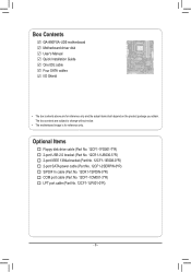
...Part No. 12CR1-1SPDIN-0*R) COM port cable (Part No. 12CF1-1CM001-3*R) LPT port cable (Part No. 12CF1-1LP001-0*R) - 6 - Box Contents GA-890FXA-UD5 motherboard Motherboard driver disk User's Manual Quick Installation Guide One IDE cable Four SATA cables I/O Shield • The box contents above are subject to change without notice.... • The motherboard image is for reference only and the actual items shall depend on the product package you obtain. The box contents are for reference ...
...Part No. 12CR1-1SPDIN-0*R) COM port cable (Part No. 12CF1-1CM001-3*R) LPT port cable (Part No. 12CF1-1LP001-0*R) - 6 - Box Contents GA-890FXA-UD5 motherboard Motherboard driver disk User's Manual Quick Installation Guide One IDE cable Four SATA cables I/O Shield • The box contents above are subject to change without notice.... • The motherboard image is for reference only and the actual items shall depend on the product package you obtain. The box contents are for reference ...
Manual
Page 7
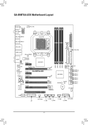
GA-890FXA-UD5 Motherboard Layout KB_MS_USB ATX_12V CPU_FAN RCA_SPDIF ATX USB_1394_ESATA2 Socket AM3 USB_1394_ESATA1 USB_LAN2 USB30_LAN1 JMicron JMB362 AUDIO Renesas D720200 F_AUDIO Realtek RTL8111D/E PCIEX1_1 NB_FAN AMD 890FX Realtek RTL8111D/E PCIEX1_2 GA-890FXA-UD5 CODEC PCIEX16_2 SPDIF_I CD_IN SPDIF_O PCIEX4 PCIEX8 IT8720 PCI PCIEX16_1 TSB43AB23 DDR3_1 DDR3_2 DDR3_3 DDR3_4 PW_SW RST_SW PWR_FAN IDE FDD GIGABYTE CMOS_SW SATA2 AMD SB850...
GA-890FXA-UD5 Motherboard Layout KB_MS_USB ATX_12V CPU_FAN RCA_SPDIF ATX USB_1394_ESATA2 Socket AM3 USB_1394_ESATA1 USB_LAN2 USB30_LAN1 JMicron JMB362 AUDIO Renesas D720200 F_AUDIO Realtek RTL8111D/E PCIEX1_1 NB_FAN AMD 890FX Realtek RTL8111D/E PCIEX1_2 GA-890FXA-UD5 CODEC PCIEX16_2 SPDIF_I CD_IN SPDIF_O PCIEX4 PCIEX8 IT8720 PCI PCIEX16_1 TSB43AB23 DDR3_1 DDR3_2 DDR3_3 DDR3_4 PW_SW RST_SW PWR_FAN IDE FDD GIGABYTE CMOS_SW SATA2 AMD SB850...
Manual
Page 8
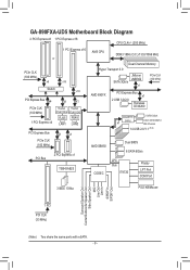
GA-890FXA-UD5 Motherboard Block Diagram 2 PCI Express x8 1 PCI Express x16 CPU CLK+/- (200 MHz) 1 PCI Express x16 or PCIe CLK (100 MHz) x8 x16 Switch x16 PCI .../1066 MHz Dual Channel Memory Hyper Transport 3.0 JMicron JMB362 SATA 3Gb/s x1 PCIe CLK (100 MHz) AMD 890FX PCI Express Bus x1 2 USB 3.0/2.0 Renesas D720200 GIGABYTE x1 SATA2 2 SATA 3Gb/s ATA-133/100/66/33 IDE Channel 14 USB 2.0/1.1 (Note) AMD SB850 Dual BIOS 6 SATA 6Gb/s CODEC LPC Bus IT8720 Floppy...
GA-890FXA-UD5 Motherboard Block Diagram 2 PCI Express x8 1 PCI Express x16 CPU CLK+/- (200 MHz) 1 PCI Express x16 or PCIe CLK (100 MHz) x8 x16 Switch x16 PCI .../1066 MHz Dual Channel Memory Hyper Transport 3.0 JMicron JMB362 SATA 3Gb/s x1 PCIe CLK (100 MHz) AMD 890FX PCI Express Bus x1 2 USB 3.0/2.0 Renesas D720200 GIGABYTE x1 SATA2 2 SATA 3Gb/s ATA-133/100/66/33 IDE Channel 14 USB 2.0/1.1 (Note) AMD SB850 Dual BIOS 6 SATA 6Gb/s CODEC LPC Bus IT8720 Floppy...

Manual
Page 9
...• Prior to wear an electrostatic discharge (ESD) wrist strap when handling electronic com- Chapter 1 Hardware Installation 1-1 Installation Precautions The motherboard contains numerous delicate electronic circuits and components which can lead to damage to system components as well as physical harm to the user. ... wrist strap, keep your hands dry and first touch a metal object to eliminate static electricity. • Prior to installing the motherboard, please have it on top of an antistatic pad or within an electrostatic shielding container. • Before unplugging the power supply...
...• Prior to wear an electrostatic discharge (ESD) wrist strap when handling electronic com- Chapter 1 Hardware Installation 1-1 Installation Precautions The motherboard contains numerous delicate electronic circuits and components which can lead to damage to system components as well as physical harm to the user. ... wrist strap, keep your hands dry and first touch a metal object to eliminate static electricity. • Prior to installing the motherboard, please have it on top of an antistatic pad or within an electrostatic shielding container. • Before unplugging the power supply...

Manual
Page 12
...Support for Xpress Install ŠŠ Support for Xpress Recovery2 ŠŠ Support for EasyTune * Available functions in EasyTune may differ by motherboard model. ŠŠ Support for Easy Energy Saver ŠŠ Support for Smart Recovery ŠŠ Support for Auto Green Š... ŠŠ Support for Microsoft® Windows 7/Vista/XP Form Factor ŠŠ ATX Form Factor; 30.5cm x 24.4cm * GIGABYTE reserves the right to make any changes to the product specifications and product-related information without prior notice. Back Panel Connectors ŠŠ 2...
...Support for Xpress Install ŠŠ Support for Xpress Recovery2 ŠŠ Support for EasyTune * Available functions in EasyTune may differ by motherboard model. ŠŠ Support for Easy Energy Saver ŠŠ Support for Smart Recovery ŠŠ Support for Auto Green Š... ŠŠ Support for Microsoft® Windows 7/Vista/XP Form Factor ŠŠ ATX Form Factor; 30.5cm x 24.4cm * GIGABYTE reserves the right to make any changes to the product specifications and product-related information without prior notice. Back Panel Connectors ŠŠ 2...
Manual
Page 13
... alignment keys on the CPU socket.) • Apply an even and thin layer of the CPU. It is not recommended that the motherboard supports the CPU. (Go to GIGABYTE's website for the peripherals. If you wish to set beyond the standard specifications, please do so according to your hardware specifications including the...
... alignment keys on the CPU socket.) • Apply an even and thin layer of the CPU. It is not recommended that the motherboard supports the CPU. (Go to GIGABYTE's website for the peripherals. If you wish to set beyond the standard specifications, please do so according to your hardware specifications including the...

Manual
Page 14
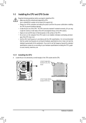
Follow the steps below to correctly install the CPU into the motherboard CPU socket. • Before installing the CPU, make sure to turn off the computer and unplug the power cord from the power outlet to prevent ...
Follow the steps below to correctly install the CPU into the motherboard CPU socket. • Before installing the CPU, make sure to turn off the computer and unplug the power cord from the power outlet to prevent ...

Manual
Page 15
...Step 5: Finally, attach the power connector of the CPU cooler to correctly install the CPU cooler on the CPU. (The following procedure uses the GIGABYTE cooler as the example.) Step 1: Apply an even and thin layer of thermal grease on the surface of the retention frame. 1-3-2 Installing the CPU... Cooler Follow the steps below to the CPU fan header (CPU_FAN) on the motherboard. Use extreme care when removing the CPU cooler because the thermal grease/tape between the CPU cooler and CPU may damage the CPU. - 15 -...
...Step 5: Finally, attach the power connector of the CPU cooler to correctly install the CPU cooler on the CPU. (The following procedure uses the GIGABYTE cooler as the example.) Step 1: Apply an even and thin layer of thermal grease on the surface of the retention frame. 1-3-2 Installing the CPU... Cooler Follow the steps below to the CPU fan header (CPU_FAN) on the motherboard. Use extreme care when removing the CPU cooler because the thermal grease/tape between the CPU cooler and CPU may damage the CPU. - 15 -...

Manual
Page 16
... memory modules, it is installed, the BIOS will double the original memory bandwidth. After the memory is recommended that the motherboard supports the memory. A memory module can be used . (Go to GIGABYTE's website for optimum performance. 1-4 Installing the Memory Read the following guidelines before you are divided into two channels and each...
... memory modules, it is installed, the BIOS will double the original memory bandwidth. After the memory is recommended that the motherboard supports the memory. A memory module can be used . (Go to GIGABYTE's website for optimum performance. 1-4 Installing the Memory Read the following guidelines before you are divided into two channels and each...
Manual
Page 17
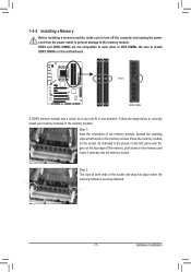
... power cord from the power outlet to prevent damage to correctly install your fingers on the top edge of the memory, push down on this motherboard. Follow the steps below to the memory module. Place the memory module on the socket. Hardware Installation
... power cord from the power outlet to prevent damage to correctly install your fingers on the top edge of the memory, push down on this motherboard. Follow the steps below to the memory module. Place the memory module on the socket. Hardware Installation

Manual
Page 18
... came with the slot, and press down on the top edge of the PCI Express slot to install an expansion card: • Make sure the motherboard supports the expansion card. Hardware Installation - 18 - • Removing the Card from the slot. Example: Installing and Removing a PCI Express Graphics Card: • Installing a Graphics...
... came with the slot, and press down on the top edge of the PCI Express slot to install an expansion card: • Make sure the motherboard supports the expansion card. Hardware Installation - 18 - • Removing the Card from the slot. Example: Installing and Removing a PCI Express Graphics Card: • Installing a Graphics...
Manual
Page 19
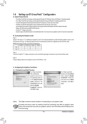
The 2-Way CrossFireX technology currently supports Windows XP, Windows Vista, and Windows 7 operating systems - A CrossFireX-supported motherboard with two/three cards. CrossFire (Note) bridge connector(s) - The following table shows the recommended CrossFireX configurations with two/three PCI Express x16 slots and correct ...
The 2-Way CrossFireX technology currently supports Windows XP, Windows Vista, and Windows 7 operating systems - A CrossFireX-supported motherboard with two/three cards. CrossFire (Note) bridge connector(s) - The following table shows the recommended CrossFireX configurations with two/three PCI Express x16 slots and correct ...

Manual
Page 20
... The IEEE 1394 port supports the IEEE 1394a specification, featuring high speed, high bandwidth and hotplug capabilities. Do not rock it straight out from the motherboard. • When removing the cable, pull it side to side to a back panel connector, first remove the cable from your device and then remove it...
... The IEEE 1394 port supports the IEEE 1394a specification, featuring high speed, high bandwidth and hotplug capabilities. Do not rock it straight out from the motherboard. • When removing the cable, pull it side to side to a back panel connector, first remove the cable from your device and then remove it...

Manual
Page 22
.../F_USB3 17) F_1394 18) LPT 19) COM 20) BAT 21) CLR_CMOS 22) PW_SW 23) RST_SW 24) CMOS_SW Read the following guidelines before turning on the motherboard. Unplug the power cord from the power outlet to prevent damage to the devices. • After installing the device and before connecting external devices: •...
.../F_USB3 17) F_1394 18) LPT 19) COM 20) BAT 21) CLR_CMOS 22) PW_SW 23) RST_SW 24) CMOS_SW Read the following guidelines before turning on the motherboard. Unplug the power cord from the power outlet to prevent damage to the devices. • After installing the device and before connecting external devices: •...

Manual
Page 23
... - To meet expansion requirements, it is not connected, the computer will not start. If a power supply is turned off and all the components on the motherboard. Before connecting the power connector, first make sure the power supply is used that can withstand high power consumption be used (500W or greater).
... - To meet expansion requirements, it is not connected, the computer will not start. If a power supply is turned off and all the components on the motherboard. Before connecting the power connector, first make sure the power supply is used that can withstand high power consumption be used (500W or greater).

Manual
Page 24
.... • These fan headers are designed with fan speed control design. Overheating may result in the correct orientation. 3/4/5) CPU_FAN/SYS_FAN1/SYS_FAN2/PWR_FAN (Fan Headers) The motherboard has a 4-pin CPU fan header (CPU_FAN), a 4-pin (SYS_FAN1) and a 3-pin (SYS_ FAN2) system fan headers, and a 3-pin power fan header (PWR_FAN). The...
.... • These fan headers are designed with fan speed control design. Overheating may result in the correct orientation. 3/4/5) CPU_FAN/SYS_FAN1/SYS_FAN2/PWR_FAN (Fan Headers) The motherboard has a 4-pin CPU fan header (CPU_FAN), a 4-pin (SYS_FAN1) and a 3-pin (SYS_ FAN2) system fan headers, and a 3-pin power fan header (PWR_FAN). The...


