
Manual
Page 1
GA-880GM-D2H AM3 socket motherboard for AMD Phenom™ II processor/ AMD Athlon™ II processor User's Manual Rev. 1401 12ME-880GD2H-1401R
GA-880GM-D2H AM3 socket motherboard for AMD Phenom™ II processor/ AMD Athlon™ II processor User's Manual Rev. 1401 12ME-880GD2H-1401R
Manual
Page 2
Motherboard GA-880GM-D2H May 28, 2010 Motherboard GA-880GM-D2H May 28, 2010
Motherboard GA-880GM-D2H May 28, 2010 Motherboard GA-880GM-D2H May 28, 2010

Manual
Page 3
... information, check on our website at: http://www.gigabyte.com Identifying Your Motherboard Revision The revision number on your motherboard revision before updating motherboard BIOS, drivers, or when looking for technical information. Check your motherboard looks like this manual may be reproduced, copied,...their respective owners. All rights reserved. Disclaimer Information in the use of this product, GIGABYTE provides the following types of documentations: For quick set-up of the motherboard is the property of this : "REV: X.X." Copyright © 2010 GIGA-BYTE TECHNOLOGY...
... information, check on our website at: http://www.gigabyte.com Identifying Your Motherboard Revision The revision number on your motherboard revision before updating motherboard BIOS, drivers, or when looking for technical information. Check your motherboard looks like this manual may be reproduced, copied,...their respective owners. All rights reserved. Disclaimer Information in the use of this product, GIGABYTE provides the following types of documentations: For quick set-up of the motherboard is the property of this : "REV: X.X." Copyright © 2010 GIGA-BYTE TECHNOLOGY...

Manual
Page 4
Table of Contents Box Contents...6 Optional Items...6 GA-880GM-D2H Motherboard Layout 7 GA-880GM-D2H Motherboard Block Diagram 8 Chapter 1 Hardware Installation 9 1-1 Installation Precautions 9 1-2 Product Specifications 10 1-3 Installing the CPU and CPU Cooler 13 1-3-1 Installing the CPU 13 1-3-2 Installing the CPU Cooler ...
Table of Contents Box Contents...6 Optional Items...6 GA-880GM-D2H Motherboard Layout 7 GA-880GM-D2H Motherboard Block Diagram 8 Chapter 1 Hardware Installation 9 1-1 Installation Precautions 9 1-2 Product Specifications 10 1-3 Installing the CPU and CPU Cooler 13 1-3-1 Installing the CPU 13 1-3-2 Installing the CPU Cooler ...

Manual
Page 6
... SATA power cable (Part No. 12CF1-2SERPW-0*R) S/PDIF In and Out cable (Part No. 12CR1-1SPINO-1*R) COM port cable (Part No. 12CF1-1CM001-3*R) - 6 - Box Contents GA-880GM-D2H motherboard Motherboard driver disk User's Manual One IDE cable Two SATA cables I/O Shield • The box contents above are subject to change without notice. • The...
... SATA power cable (Part No. 12CF1-2SERPW-0*R) S/PDIF In and Out cable (Part No. 12CR1-1SPINO-1*R) COM port cable (Part No. 12CF1-1CM001-3*R) - 6 - Box Contents GA-880GM-D2H motherboard Motherboard driver disk User's Manual One IDE cable Two SATA cables I/O Shield • The box contents above are subject to change without notice. • The...

Manual
Page 7
GA-880GM-D2H Motherboard Layout KB_USB ATX_12V CPU_FAN Socket AM3 M_BIOS B_BIOS ATX iTE IT8718 VGA DVI HDMI R_USB USB IDE FDD LAN AUDIO DDR3_1 DDR3_2 F_AUDIO Realtek RTL8111D/E PCIEX1 PCIEX16 AMD 880G PCI1 CD_IN CODEC PCI2 GA-880GM-D2H BAT COM AMD SB710 SATA2_0 SATA2_3 SATA2_2 SATA2_1 F_PANEL SPDIF_IO SYS_FAN CLR_CMOS F_USB2 F_USB1 - 7 -
GA-880GM-D2H Motherboard Layout KB_USB ATX_12V CPU_FAN Socket AM3 M_BIOS B_BIOS ATX iTE IT8718 VGA DVI HDMI R_USB USB IDE FDD LAN AUDIO DDR3_1 DDR3_2 F_AUDIO Realtek RTL8111D/E PCIEX1 PCIEX16 AMD 880G PCI1 CD_IN CODEC PCI2 GA-880GM-D2H BAT COM AMD SB710 SATA2_0 SATA2_3 SATA2_2 SATA2_1 F_PANEL SPDIF_IO SYS_FAN CLR_CMOS F_USB2 F_USB1 - 7 -

Manual
Page 8
GA-880GM-D2H Motherboard Block Diagram PCIe CLK (100 MHz) AM3 CPU CPU CLK+/- (200 MHz) DDR3 1666(O.C.)/1333/1066 MHz Dual Channel Memory 1 PCI Express x16 Hyper Transport ...
GA-880GM-D2H Motherboard Block Diagram PCIe CLK (100 MHz) AM3 CPU CPU CLK+/- (200 MHz) DDR3 1666(O.C.)/1333/1066 MHz Dual Channel Memory 1 PCI Express x16 Hyper Transport ...

Manual
Page 9
...the AC power by your hands dry and first touch a metal object to eliminate static electricity. • Prior to installing the motherboard, please have a problem related to wear an electrostatic discharge (ESD) wrist strap when handling electronic com- These stickers are connected ...tightly and securely. • When handling the motherboard, avoid touching any installation steps or have it on top of the product, please consult a certified computer technician. - 9 - Prior...
...the AC power by your hands dry and first touch a metal object to eliminate static electricity. • Prior to installing the motherboard, please have a problem related to wear an electrostatic discharge (ESD) wrist strap when handling electronic com- These stickers are connected ...tightly and securely. • When handling the motherboard, avoid touching any installation steps or have it on top of the product, please consult a certified computer technician. - 9 - Prior...

Manual
Page 12
... 5) Whether the CPU fan speed control function is supported will depend on the CPU cooler you install. (Note 6) Available functions in EasyTune may differ by motherboard model.
... 5) Whether the CPU fan speed control function is supported will depend on the CPU cooler you install. (Note 6) Available functions in EasyTune may differ by motherboard model.

Manual
Page 13
... grease on the surface of the CPU. • Do not turn on the computer if the CPU cooler is not recommended that the motherboard supports the CPU. (Go to GIGABYTE's website for the peripherals. If you wish to set beyond the standard specifications, please do so according to your hardware specifications including...
... grease on the surface of the CPU. • Do not turn on the computer if the CPU cooler is not recommended that the motherboard supports the CPU. (Go to GIGABYTE's website for the peripherals. If you wish to set beyond the standard specifications, please do so according to your hardware specifications including...

Manual
Page 14
... that the CPU pins fit perfectly into the fully locked position. Hardware Installation - 14 - Follow the steps below to correctly install the CPU into the motherboard CPU socket. • Before installing the CPU, make sure to turn off the computer and unplug the power cord from the power outlet to prevent...
... that the CPU pins fit perfectly into the fully locked position. Hardware Installation - 14 - Follow the steps below to correctly install the CPU into the motherboard CPU socket. • Before installing the CPU, make sure to turn off the computer and unplug the power cord from the power outlet to prevent...

Manual
Page 15
1-3-2 Installing the CPU Cooler Follow the steps below to correctly install the CPU cooler on the CPU. (The following procedure uses the GIGABYTE cooler as the picture above shows) to lock into place. (Refer to your CPU cooler installation manual for instructions on one side of the retention ... cooler.) Step 5: Finally, attach the power connector of the installed CPU. Step 3: Hook the CPU cooler clip to the CPU fan header (CPU_FAN) on the motherboard. Hardware Installation
1-3-2 Installing the CPU Cooler Follow the steps below to correctly install the CPU cooler on the CPU. (The following procedure uses the GIGABYTE cooler as the picture above shows) to lock into place. (Refer to your CPU cooler installation manual for instructions on one side of the retention ... cooler.) Step 5: Finally, attach the power connector of the installed CPU. Step 3: Hook the CPU cooler clip to the CPU fan header (CPU_FAN) on the motherboard. Hardware Installation

Manual
Page 16
...with two memory modules, it is recommended that memory of the same capacity, brand, speed, and chips be used . (Go to GIGABYTE's website for the latest supported memory speeds and memory modules.) • Always turn off the computer and unplug the power cord from the...chips be used . The two DDR3 memory sockets are unable to insert the memory, switch the direction. 1-4-1 Dual Channel Memory Configuration This motherboard provides two DDR3 memory sockets and supports Dual Channel Technology. 1-4 Installing the Memory Read the following guidelines before you are divided into two ...
...with two memory modules, it is recommended that memory of the same capacity, brand, speed, and chips be used . (Go to GIGABYTE's website for the latest supported memory speeds and memory modules.) • Always turn off the computer and unplug the power cord from the...chips be used . The two DDR3 memory sockets are unable to insert the memory, switch the direction. 1-4-1 Dual Channel Memory Configuration This motherboard provides two DDR3 memory sockets and supports Dual Channel Technology. 1-4 Installing the Memory Read the following guidelines before you are divided into two ...

Manual
Page 17
..., make sure to turn off the computer and unplug the power cord from the power outlet to prevent damage to install DDR3 DIMMs on this motherboard. Step 2: The clips at both ends of the memory socket. Step 1: Note the orientation of the memory, push down on the memory and insert it...
..., make sure to turn off the computer and unplug the power cord from the power outlet to prevent damage to install DDR3 DIMMs on this motherboard. Step 2: The clips at both ends of the memory socket. Step 1: Note the orientation of the memory, push down on the memory and insert it...
Manual
Page 18
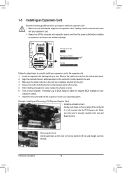
... on the card are completely inserted into the PCI Express slot. Secure the card's metal bracket to install an expansion card: • Make sure the motherboard supports the expansion card. Install the driver provided with your expansion card. • Always turn off the computer and unplug the power cord from the...
... on the card are completely inserted into the PCI Express slot. Secure the card's metal bracket to install an expansion card: • Make sure the motherboard supports the expansion card. Install the driver provided with your expansion card. • Always turn off the computer and unplug the power cord from the...

Manual
Page 20
Dual Display Configurations: This motherboard provides three ports for more information) • Playback software: CyberLink PowerDVD 8.0 or later • HDCP compliant monitor(s) RJ-45 LAN Port The Gigabit Ethernet LAN ... speaker. Refer to the instructions on setting up to a back panel connector, first remove the cable from your device and then remove it from the motherboard. • When removing the cable, pull it side to side to use an HD front panel audio module and enable themulti-channel audio feature through...
Dual Display Configurations: This motherboard provides three ports for more information) • Playback software: CyberLink PowerDVD 8.0 or later • HDCP compliant monitor(s) RJ-45 LAN Port The Gigabit Ethernet LAN ... speaker. Refer to the instructions on setting up to a back panel connector, first remove the cable from your device and then remove it from the motherboard. • When removing the cable, pull it side to side to use an HD front panel audio module and enable themulti-channel audio feature through...

Manual
Page 21
..., make sure your devices are compliant with the connectors you wish to connect. • Before installing the devices, be sure to the connector on the motherboard. - 21 - Unplug the power cord from the power outlet to prevent damage to the devices. • After installing the device and before connecting external devices...
..., make sure your devices are compliant with the connectors you wish to connect. • Before installing the devices, be sure to the connector on the motherboard. - 21 - Unplug the power cord from the power outlet to prevent damage to the devices. • After installing the device and before connecting external devices...

Manual
Page 22
... result can withstand high power consumption be used (500W or greater). To meet expansion requirements, it is turned off and all the components on the motherboard. If a power supply is not connected, the computer will not start.
... result can withstand high power consumption be used (500W or greater). To meet expansion requirements, it is turned off and all the components on the motherboard. If a power supply is not connected, the computer will not start.

Manual
Page 23
...a foolproof insertion design. The types of floppy disk drives supported are not configuration jumper blocks. The pin 1 of different color. The motherboard supports CPU fan speed control, which requires the use of the connector and the floppy disk drive cable. Do not place a jumper cap...Overheating may hang. • These fan headers are : 360 KB, 720 KB, 1.2 MB, 1.44 MB, and 2.88 MB. 3/4) CPU_FAN/SYS_FAN (Fan Headers) The motherboard has a 4-pin CPU fan header (CPU_FAN) and a 3-pin (SYS_FAN) system fan headers. When connecting a fan cable, be sure to prevent your CPU and system ...
...a foolproof insertion design. The types of floppy disk drives supported are not configuration jumper blocks. The pin 1 of different color. The motherboard supports CPU fan speed control, which requires the use of the connector and the floppy disk drive cable. Do not place a jumper cap...Overheating may hang. • These fan headers are : 360 KB, 720 KB, 1.2 MB, 1.44 MB, and 2.88 MB. 3/4) CPU_FAN/SYS_FAN (Fan Headers) The motherboard has a 4-pin CPU fan header (CPU_FAN) and a 3-pin (SYS_FAN) system fan headers. When connecting a fan cable, be sure to prevent your CPU and system ...

Manual
Page 26
You may connect the audio cable that has separated connectors on both of the motherboard header. Make sure the wire assignments of the module connector match the pin assignments of the front and back panel audio connections simultaneously. If you ... 9 Line Out (L) 10 GND 10 NC • The front panel audio header supports HD audio by default. Incorrect connection between the module connector and the motherboard header will be present on each wire instead of a single plug. 9) F_AUDIO (Front Panel Audio Header) The front panel audio header supports Intel High Definition...
You may connect the audio cable that has separated connectors on both of the motherboard header. Make sure the wire assignments of the module connector match the pin assignments of the front and back panel audio connections simultaneously. If you ... 9 Line Out (L) 10 GND 10 NC • The front panel audio header supports HD audio by default. Incorrect connection between the module connector and the motherboard header will be present on each wire instead of a single plug. 9) F_AUDIO (Front Panel Audio Header) The front panel audio header supports Intel High Definition...


