
Installation Instructions
Page 1
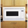
Cabinet Cutout Dimensions and Specifications Allow 1-1⁄4" for overlap of the Microwave Oven Kit Trim over any General Electric/Hotpoint/RCA single electric wall oven. • Do not alter or modify any part of this kit. • Save these instructions, Owner's Manual and Important Safety Instructions completely and carefully. • This Kit is for use on models: JEM21K/L, JEM23K/L, JEM25L/GN/GV/GY/WN/WV/WY/BF/WF, JES833WY, JEM825K, JEM27KWH/LWH, JEM31L/M/GN...
Cabinet Cutout Dimensions and Specifications Allow 1-1⁄4" for overlap of the Microwave Oven Kit Trim over any General Electric/Hotpoint/RCA single electric wall oven. • Do not alter or modify any part of this kit. • Save these instructions, Owner's Manual and Important Safety Instructions completely and carefully. • This Kit is for use on models: JEM21K/L, JEM23K/L, JEM25L/GN/GV/GY/WN/WV/WY/BF/WF, JES833WY, JEM825K, JEM27KWH/LWH, JEM31L/M/GN...

Installation Instructions
Page 2
.../60 Hertz Grounded Power Outlet using four Screws (B). Tools Needed 2 Phillips head screwdrivers (#1 & #2) Drill and 3/32" drill bit Centerpunch or nail Pencil and ruler Knife Installation Procedure Step 1 Locating and Installing Rear Holddown Supports Set Base Pan (1) into the Base Pan front flange to hold in place temporarily. The tongues of the microwave oven (packing, glass shelf, temperature probe, Use & Care books). If applied, remove the film.
.../60 Hertz Grounded Power Outlet using four Screws (B). Tools Needed 2 Phillips head screwdrivers (#1 & #2) Drill and 3/32" drill bit Centerpunch or nail Pencil and ruler Knife Installation Procedure Step 1 Locating and Installing Rear Holddown Supports Set Base Pan (1) into the Base Pan front flange to hold in place temporarily. The tongues of the microwave oven (packing, glass shelf, temperature probe, Use & Care books). If applied, remove the film.

Installation Instructions
Page 3
... on the top left in Steps 3 & 4 tightened. Remove the screw located on the right side. The unit should be completely sealed to left back of the Microwave Oven Plug the power cord into the cabinet using care not to pinch the power cord, and to keep it centered as possible. Screws E Screw A Screw E SARVEEMSOCVREE&W Screws A CAUTION: Start all screws installed in the opening and the Base Pan front flange tight...
... on the top left in Steps 3 & 4 tightened. Remove the screw located on the right side. The unit should be completely sealed to left back of the Microwave Oven Plug the power cord into the cabinet using care not to pinch the power cord, and to keep it centered as possible. Screws E Screw A Screw E SARVEEMSOCVREE&W Screws A CAUTION: Start all screws installed in the opening and the Base Pan front flange tight...

Installation Instructions
Page 4
... Mark Wall Installation CAUTION: Do not overtighten screws since it with the microwave oven in place by starting the four screws that attach the trim kit frame to the Base Pan and Side Covers. No. 31-1163 (2) SPECIFICATIONS SUBJECT TO CHANGE WITHOUT NOTICE (N.D. 558) 7/02 Push the Trim Kit Frame as far to prevent burring the Phillips head. Using the assembled Trim Kit Frame as a template (and with 8 screws (C). Screw C Part No...
... Mark Wall Installation CAUTION: Do not overtighten screws since it with the microwave oven in place by starting the four screws that attach the trim kit frame to the Base Pan and Side Covers. No. 31-1163 (2) SPECIFICATIONS SUBJECT TO CHANGE WITHOUT NOTICE (N.D. 558) 7/02 Push the Trim Kit Frame as far to prevent burring the Phillips head. Using the assembled Trim Kit Frame as a template (and with 8 screws (C). Screw C Part No...


