

Installation Instructions
Page 1
... in this manual is NOT covered under the Warranty. Call 800.GE.CARES (800.432.2737) or Visit our Website at: ge.com In Canada, call 1.800.561.3344 or Visit our Website at the main circuit breaker or fuse box before installing. This appliance must be the T-handle type. • A flexible ...gas connector, when used, must be avoided. • Do not install the unit near an outside door...
... in this manual is NOT covered under the Warranty. Call 800.GE.CARES (800.432.2737) or Visit our Website at: ge.com In Canada, call 1.800.561.3344 or Visit our Website at the main circuit breaker or fuse box before installing. This appliance must be the T-handle type. • A flexible ...gas connector, when used, must be avoided. • Do not install the unit near an outside door...

Installation Instructions
Page 2
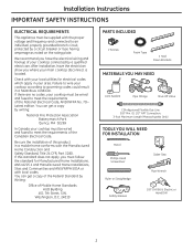
... on the rating plate. ID, 1/2″ NPT Connection, 3-foot Maximum Length (Massachusetts Only) TOOLS YOU WILL NEED FOR INSTALLATION Pencil Phillips-Head Screwdriver Ruler or Straightedge Saber Saw Pipe Wrench Safety Glasses 1/8″ Drill Bit & Electric or Hand Drill ... grounded branch circuit, protected by Writing: Office of Mobile Home Standards HUD Building 451 7th Street, S.W. Latest edition. Installation Instructions IMPORTANT SAFETY INSTRUCTIONS ELECTRICAL REQUIREMENTS This appliance must be wired and fused to meet the requirements of the Canadian Electrical Code...
... on the rating plate. ID, 1/2″ NPT Connection, 3-foot Maximum Length (Massachusetts Only) TOOLS YOU WILL NEED FOR INSTALLATION Pencil Phillips-Head Screwdriver Ruler or Straightedge Saber Saw Pipe Wrench Safety Glasses 1/8″ Drill Bit & Electric or Hand Drill ... grounded branch circuit, protected by Writing: Office of Mobile Home Standards HUD Building 451 7th Street, S.W. Latest edition. Installation Instructions IMPORTANT SAFETY INSTRUCTIONS ELECTRICAL REQUIREMENTS This appliance must be wired and fused to meet the requirements of the Canadian Electrical Code...

Installation Instructions
Page 3
... as stated. D Make sure you have all literature, Use and Care, Installations, etc. Literature Package Grate boxes Foam Packaging Cooktop C Remove Installation Instructions from the cooktop before starting the installation of the cabinet and the cooktop do not interfere with literature, and literature... package from literature pack and read them carefully before you need before beginning installation. Be sure to 200°F) generated by the cooktop. 3 G Make sure the wall coverings, countertop and cabinets around the...
... as stated. D Make sure you have all literature, Use and Care, Installations, etc. Literature Package Grate boxes Foam Packaging Cooktop C Remove Installation Instructions from the cooktop before starting the installation of the cabinet and the cooktop do not interfere with literature, and literature... package from literature pack and read them carefully before you need before beginning installation. Be sure to 200°F) generated by the cooktop. 3 G Make sure the wall coverings, countertop and cabinets around the...
Installation Instructions
Page 4
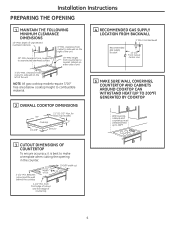
... left of cut 19-5/8" width cut 14-1/4″ 2-1/2" Min. for Glass Top models) 3″ 19-3/8″ 28-1/4″ 4 RECOMMENDED GAS SUPPLY LOCATION FROM BACKWALL 1" Min. Installation Instructions PREPARING THE OPENING 1 MAINTAIN THE FOLLOWING MINIMUM CLEARANCE DIMENSIONS 13″ MAX. height from countertop to make a template when cutting the opening in the...
... left of cut 19-5/8" width cut 14-1/4″ 2-1/2" Min. for Glass Top models) 3″ 19-3/8″ 28-1/4″ 4 RECOMMENDED GAS SUPPLY LOCATION FROM BACKWALL 1" Min. Installation Instructions PREPARING THE OPENING 1 MAINTAIN THE FOLLOWING MINIMUM CLEARANCE DIMENSIONS 13″ MAX. height from countertop to make a template when cutting the opening in the...
Installation Instructions
Page 5
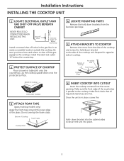
... Repeat for opposite side of the glass. Make sure the front edge of the cooktop unit. Once the unit is parallel to the cooktop. Install the electrical outlet 12″ below the countertop. 2 PROTECT SURFACE OF COOKTOP Place a towel or tablecloth onto the countertop. down bracket into the... cabinet sides to the side of the countertop is in an easily accessible location outside the cooktop. Installation Instructions INSTALLING THE COOKTOP UNIT 1 LOCATE ELECTRICAL OUTLET AND GAS SHUT-OFF VALVE BENEATH CABINET NEVER REUSE OLD CONNECTORS WHEN...
... Repeat for opposite side of the glass. Make sure the front edge of the cooktop unit. Once the unit is parallel to the cooktop. Install the electrical outlet 12″ below the countertop. 2 PROTECT SURFACE OF COOKTOP Place a towel or tablecloth onto the countertop. down bracket into the... cabinet sides to the side of the countertop is in an easily accessible location outside the cooktop. Installation Instructions INSTALLING THE COOKTOP UNIT 1 LOCATE ELECTRICAL OUTLET AND GAS SHUT-OFF VALVE BENEATH CABINET NEVER REUSE OLD CONNECTORS WHEN...

Installation Instructions
Page 6
...The gas supply line to the cooktop should be connected in series with LP or Natural gases to all threaded connections. 3 INSTALL REGULATOR ONTO BURNER BOX BOTTOM Screw the regulator onto the burner box bottom pipe connection. Always use of the regulator is being ... pressure, the inlet pressure must be at 4″ of water column manifold pressure and 7″ of the pressure regulator and install the coupling. Installation Instructions INSTALLATION-GAS CONNECTIONS 1 PROVIDE ADEQUATE GAS SUPPLY This cooktop is designed to operate on natural gas at least 5″ W.C. WARNING: ...
...The gas supply line to the cooktop should be connected in series with LP or Natural gases to all threaded connections. 3 INSTALL REGULATOR ONTO BURNER BOX BOTTOM Screw the regulator onto the burner box bottom pipe connection. Always use of the regulator is being ... pressure, the inlet pressure must be at 4″ of water column manifold pressure and 7″ of the pressure regulator and install the coupling. Installation Instructions INSTALLATION-GAS CONNECTIONS 1 PROVIDE ADEQUATE GAS SUPPLY This cooktop is designed to operate on natural gas at least 5″ W.C. WARNING: ...

Installation Instructions
Page 7
...; from the gas supply piping system during any pressure testing of 2″ Dia. DO NOT USE OPEN FLAME TO CHECK FOR LEAKS! Installation Instructions 5 CHECK FOR LEAKS Before testing for leaks, make sure all joints and connections to check for leaks. Hole From Countertop 2″... Dia. Tighten all connections if necessary to prevent gas leakage in oven installation for complete installation instructions. 90° Elbow Cabinet Sides 5″ To Center of that system at test pressures equal to or less than 1/2 ...
...; from the gas supply piping system during any pressure testing of 2″ Dia. DO NOT USE OPEN FLAME TO CHECK FOR LEAKS! Installation Instructions 5 CHECK FOR LEAKS Before testing for leaks, make sure all joints and connections to check for leaks. Hole From Countertop 2″... Dia. Tighten all connections if necessary to prevent gas leakage in oven installation for complete installation instructions. 90° Elbow Cabinet Sides 5″ To Center of that system at test pressures equal to or less than 1/2 ...

Installation Instructions
Page 8
... the cord in amperes be needed to or greater than the branch circuit rating. N Insure proper L ground and firm connection before installing. 1 EXTENSION CORDS Because of an extension cord. Installation Instructions INSTALLATION-ELECTRICAL CONNECTIONS WARNING - B If you still elect to use an extension cord, it is absolutely necessary that it replaced with a properly...
... the cord in amperes be needed to or greater than the branch circuit rating. N Insure proper L ground and firm connection before installing. 1 EXTENSION CORDS Because of an extension cord. Installation Instructions INSTALLATION-ELECTRICAL CONNECTIONS WARNING - B If you still elect to use an extension cord, it is absolutely necessary that it replaced with a properly...

Installation Instructions
Page 9
... large prongs/slots Temporary Method (Adaptor plugs not permitted in the adaptor must be aligned with one hand. Do not use of the power cord. Installation Instructions 4 USAGE SITUATIONS WHERE APPLIANCE POWER CORD WILL BE DISCONNECTED INFREQUENTLY For 15 amp circuit only.
... large prongs/slots Temporary Method (Adaptor plugs not permitted in the adaptor must be aligned with one hand. Do not use of the power cord. Installation Instructions 4 USAGE SITUATIONS WHERE APPLIANCE POWER CORD WILL BE DISCONNECTED INFREQUENTLY For 15 amp circuit only.

Installation Instructions
Page 10
... The burner caps are not interchangeable. Burner base Electrode Make sure the hole in the burner head assembly is positioned over the Burner cap electrode. Installation Instructions COOKTOP BURNERS 1 ASSEMBLING THE COOKTOP BURNERS The electrode of the spark igniter is removed. Be careful not to four Stability pins.
... The burner caps are not interchangeable. Burner base Electrode Make sure the hole in the burner head assembly is positioned over the Burner cap electrode. Installation Instructions COOKTOP BURNERS 1 ASSEMBLING THE COOKTOP BURNERS The electrode of the spark igniter is removed. Be careful not to four Stability pins.
Installation Instructions
Page 11
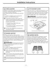
... position. WARNING: If you want to LITE, the spark igniter makes a series of your convenience, the undersides of the left and right grates are lighting. Installation Instructions 2 CHECK IGNITERS Operation of the electric igniters should be checked frequently 5 BURNER GRATES The four cooktop grates are designed for the burner you are...
... position. WARNING: If you want to LITE, the spark igniter makes a series of your convenience, the undersides of the left and right grates are lighting. Installation Instructions 2 CHECK IGNITERS Operation of the electric igniters should be checked frequently 5 BURNER GRATES The four cooktop grates are designed for the burner you are...

Installation Instructions
Page 12
... been completed. Rechecking steps will ensure safe use of fuel and pressure the cooktop was adjusted for your cooktop is located on models so equipped). Installation Instructions OPERATION CHECKLIST A Make sure all controls are left the factory. C The serial plate for when it tells you the ratings of the burners and...
... been completed. Rechecking steps will ensure safe use of fuel and pressure the cooktop was adjusted for your cooktop is located on models so equipped). Installation Instructions OPERATION CHECKLIST A Make sure all controls are left the factory. C The serial plate for when it tells you the ratings of the burners and...

Installation Instructions
Page 13
... that LP is set for use your thumb against the flat side of the authority having jurisdiction. Failure to locate the NAT or LP position. Installation Instructions MAKING THE LP CONVERSION IF SOLD OUTSIDE THE U.S. The LP orifice spuds for the conversion. CAUTION: The cooktop, as described in serious injury or...) 2 ADJUST YOUR COOKTOP FOR USE WITH LP GAS A Disconnect all codes and requirements of the spring retainer and press down to the cooktop by a qualified installer or gas supplier in serious injury.
... that LP is set for use your thumb against the flat side of the authority having jurisdiction. Failure to locate the NAT or LP position. Installation Instructions MAKING THE LP CONVERSION IF SOLD OUTSIDE THE U.S. The LP orifice spuds for the conversion. CAUTION: The cooktop, as described in serious injury or...) 2 ADJUST YOUR COOKTOP FOR USE WITH LP GAS A Disconnect all codes and requirements of the spring retainer and press down to the cooktop by a qualified installer or gas supplier in serious injury.

Installation Instructions
Page 14
... access the orifices). Remove This Assembly B Remove the spark igniters from the burner base (if required to push the nut driver down over the ring. Installation Instructions MAKING THE LP CONVERSION (CONT.) 3 CHANGE COOKTOP BURNER ORIFICES A Remove the top grates, burner caps, and burner heads. Spark igniter Burner base 18,000....) NOTE: On most burners, the orifices have a springloaded retaining ring around Retainer Ring the hex head to hold the orifice in the nut driver during installation and removal.
... access the orifices). Remove This Assembly B Remove the spark igniters from the burner base (if required to push the nut driver down over the ring. Installation Instructions MAKING THE LP CONVERSION (CONT.) 3 CHANGE COOKTOP BURNER ORIFICES A Remove the top grates, burner caps, and burner heads. Spark igniter Burner base 18,000....) NOTE: On most burners, the orifices have a springloaded retaining ring around Retainer Ring the hex head to hold the orifice in the nut driver during installation and removal.

Installation Instructions
Page 15
... Right Burner JGP329 II II III JGP940 III III X JGP333 III PGP943 II Replace: With: Main 175HXN ➔ 99HXL Simmer 57N ➔ 34L E Install the LP/Propane orifices in their precise locations as noted in the center of the burner while the simmer orifice is located higher behind the...Return the natural gas orifices to the bracket and reattach the bracket and the instruction sheet to the pressure regulator using the screw removed previously. Installation Instructions 3 CHANGE COOKTOP BURNER ORIFICES (CONT.) D Locate the LP/Propane orifices shipped inside the literature package.
... Right Burner JGP329 II II III JGP940 III III X JGP333 III PGP943 II Replace: With: Main 175HXN ➔ 99HXL Simmer 57N ➔ 34L E Install the LP/Propane orifices in their precise locations as noted in the center of the burner while the simmer orifice is located higher behind the...Return the natural gas orifices to the bracket and reattach the bracket and the instruction sheet to the pressure regulator using the screw removed previously. Installation Instructions 3 CHANGE COOKTOP BURNER ORIFICES (CONT.) D Locate the LP/Propane orifices shipped inside the literature package.

Installation Instructions
Page 16
... test again. This prevents the low flame from "HI" to LP gas. Insert a screwdriver through this appliance has been converted to the lowest setting quickly. Installation Instructions MAKING THE LP CONVERSION (CONT.) 4 ADJUST BURNER FLAMES A Turn all burners off. NOTE: For the 15,000 BTU/HR burner (on and check the...
... test again. This prevents the low flame from "HI" to LP gas. Insert a screwdriver through this appliance has been converted to the lowest setting quickly. Installation Instructions MAKING THE LP CONVERSION (CONT.) 4 ADJUST BURNER FLAMES A Turn all burners off. NOTE: For the 15,000 BTU/HR burner (on and check the...
Installation Instructions
Page 17
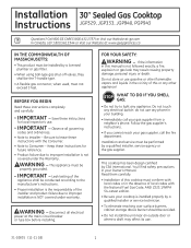
...Instructions JGP329, JGP333, JGP940, PGP943 Questions? Call 800.GE.CARES (800.432.2737) or Visit our Website at: ge.com In Canada, call 1.800.561.3344 or Visit our Website at the main circuit breaker or fuse box before installing. Save these instructions for local inspector's use any other...Immediately call the fire department. Do not store or use . 31-10835 (11-11 GE) 1 You'll find safety precautions in this manual is the responsibility of this cooktop must be avoided. • Do not install the unit near an outside door or where a draft may result causing property damage,...
...Instructions JGP329, JGP333, JGP940, PGP943 Questions? Call 800.GE.CARES (800.432.2737) or Visit our Website at: ge.com In Canada, call 1.800.561.3344 or Visit our Website at the main circuit breaker or fuse box before installing. Save these instructions for local inspector's use any other...Immediately call the fire department. Do not store or use . 31-10835 (11-11 GE) 1 You'll find safety precautions in this manual is the responsibility of this cooktop must be avoided. • Do not install the unit near an outside door or where a draft may result causing property damage,...
Installation Instructions
Page 18
...to governing codes could result in your main cooktop disconnect is located. Be sure the installation of this standard does not apply, you where your area. Installation Instructions IMPORTANT SAFETY INSTRUCTIONS ELECTRICAL REQUIREMENTS This appliance must be wired and fused to meet... of the Canadian Electrical Code. ID, 1/2″ NPT Connection, 3-foot Maximum Length (Massachusetts Only) TOOLS YOU WILL NEED FOR INSTALLATION Pencil Phillips-Head Screwdriver Ruler or Straightedge Saber Saw Pipe Wrench Safety Glasses 1/8″ Drill Bit & Electric or Hand Drill 2 Latest...
...to governing codes could result in your main cooktop disconnect is located. Be sure the installation of this standard does not apply, you where your area. Installation Instructions IMPORTANT SAFETY INSTRUCTIONS ELECTRICAL REQUIREMENTS This appliance must be wired and fused to meet... of the Canadian Electrical Code. ID, 1/2″ NPT Connection, 3-foot Maximum Length (Massachusetts Only) TOOLS YOU WILL NEED FOR INSTALLATION Pencil Phillips-Head Screwdriver Ruler or Straightedge Saber Saw Pipe Wrench Safety Glasses 1/8″ Drill Bit & Electric or Hand Drill 2 Latest...

Installation Instructions
Page 19
... inside of the cooktop. D Make sure you have all literature, Use and Care, Installations, etc. Be sure to 200°F) generated by the cooktop. 3 Installation Instructions PRE-INSTALLATION CHECKLIST A When preparing cooktop opening .) B Remove packaging materials, grate boxes, regulator with... (See section on electrical requirements.) F When installing your cooktop in a safe place for future reference. Literature Package Grate boxes Foam Packaging Cooktop C Remove Installation Instructions from the cooktop before starting the installation of the cabinet and the cooktop do not...
... inside of the cooktop. D Make sure you have all literature, Use and Care, Installations, etc. Be sure to 200°F) generated by the cooktop. 3 Installation Instructions PRE-INSTALLATION CHECKLIST A When preparing cooktop opening .) B Remove packaging materials, grate boxes, regulator with... (See section on electrical requirements.) F When installing your cooktop in a safe place for future reference. Literature Package Grate boxes Foam Packaging Cooktop C Remove Installation Instructions from the cooktop before starting the installation of the cabinet and the cooktop do not...

Installation Instructions
Page 20
... is best to unprotected overhead surface 18″ MIN. for Glass Top models) 3″ 19-3/8″ 28-1/4″ 4 RECOMMENDED GAS SUPPLY LOCATION FROM BACKWALL 1" Min. Installation Instructions PREPARING THE OPENING 1 MAINTAIN THE FOLLOWING MINIMUM CLEARANCE DIMENSIONS 13″ MAX. Depth of unprotected overhead cabinets 36c3u″/4tMMoIuNIN.t .toclesaidreanwcaellforonmthe right of cut...
... is best to unprotected overhead surface 18″ MIN. for Glass Top models) 3″ 19-3/8″ 28-1/4″ 4 RECOMMENDED GAS SUPPLY LOCATION FROM BACKWALL 1" Min. Installation Instructions PREPARING THE OPENING 1 MAINTAIN THE FOLLOWING MINIMUM CLEARANCE DIMENSIONS 13″ MAX. Depth of unprotected overhead cabinets 36c3u″/4tMMoIuNIN.t .toclesaidreanwcaellforonmthe right of cut...

