
Installation Instructions
Page 1
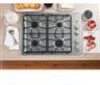
...BEFORE YOU BEGIN Read these instructions for local inspector's use . 31-10835 (11-11 GE) 1 If the information in the absence of this cooktop must not exceed 3 feet. Installation 30″ Sealed Gas Cooktop Instructions JGP329, JGP333, JGP940, PGP943 Questions? Observe all electrical power at : www....carefully. • Installation of this or any electrical switch; WARNING - Call 800.GE.CARES (800.432.2737) or Visit our Website at: ge.com In Canada, call the fire department. This cooktop has been design certified by a qualified installer or service technician. • To...
...BEFORE YOU BEGIN Read these instructions for local inspector's use . 31-10835 (11-11 GE) 1 If the information in the absence of this cooktop must not exceed 3 feet. Installation 30″ Sealed Gas Cooktop Instructions JGP329, JGP333, JGP940, PGP943 Questions? Observe all electrical power at : www....carefully. • Installation of this or any electrical switch; WARNING - Call 800.GE.CARES (800.432.2737) or Visit our Website at: ge.com In Canada, call the fire department. This cooktop has been design certified by a qualified installer or service technician. • To...

Installation Instructions
Page 2
... HUD Building 451 7th Street, S.W. Failure to wire your cooktop according to governing codes could result in your cooktop connected by writing: National Fire Protection Association Batterymarch Park Quincy, MA 02269 In Canada your cooktop must be wired and fused to meet the requirements of the...Joint Sealant Pipe Fittings Shut-Off Valve CSA-Approved Flexible Gas Line 3/8″ Min. Check with your main cooktop disconnect is located. If there are no codes, your cooktop must follow the standard for electrical codes which apply in a hazardous condition. If this product in a ...
... HUD Building 451 7th Street, S.W. Failure to wire your cooktop according to governing codes could result in your cooktop connected by writing: National Fire Protection Association Batterymarch Park Quincy, MA 02269 In Canada your cooktop must be wired and fused to meet the requirements of the...Joint Sealant Pipe Fittings Shut-Off Valve CSA-Approved Flexible Gas Line 3/8″ Min. Check with your main cooktop disconnect is located. If there are no codes, your cooktop must follow the standard for electrical codes which apply in a hazardous condition. If this product in a ...

Installation Instructions
Page 3
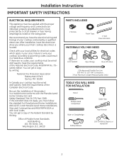
...to section on preparing the opening , make sure all literature, Use and Care, Installations, etc. in your cooktop. (Refer to 200°F) generated by the cooktop. 3 D Make sure you have all the tools and materials you begin. E Your home must provide the ...adequate electrical service needed to safely and properly use your home, make sure the inside of the cooktop. Installation Instructions PRE-INSTALLATION CHECKLIST A When preparing cooktop opening .) B Remove packaging materials, grate boxes, regulator with each other. (See section on electrical requirements.) ...
...to section on preparing the opening , make sure all literature, Use and Care, Installations, etc. in your cooktop. (Refer to 200°F) generated by the cooktop. 3 D Make sure you have all the tools and materials you begin. E Your home must provide the ...adequate electrical service needed to safely and properly use your home, make sure the inside of the cooktop. Installation Instructions PRE-INSTALLATION CHECKLIST A When preparing cooktop opening .) B Remove packaging materials, grate boxes, regulator with each other. (See section on electrical requirements.) ...
Installation Instructions
Page 4
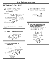
...Recommended gas supply location 13-1/4″ From Cutout Center Line 5 MAKE SURE WALL COVERINGS, COUNTERTOP AND CABINETS AROUND COOKTOP CAN WITHSTAND HEAT (UP TO 200°F) GENERATED BY COOKTOP Wall covering, cabinets and countertop must withstand heat up to 200°F 3 CUTOUT DIMENSIONS OF COUNTERTOP To ...ensure accuracy, it is best to nearest cabinet on the left of the unit NOTE: All gas cooktop models require 7/16″ free area below cooktop height to unprotected overhead surface 18″ MIN. height from cutout to side wall on either side of countertop ...
...Recommended gas supply location 13-1/4″ From Cutout Center Line 5 MAKE SURE WALL COVERINGS, COUNTERTOP AND CABINETS AROUND COOKTOP CAN WITHSTAND HEAT (UP TO 200°F) GENERATED BY COOKTOP Wall covering, cabinets and countertop must withstand heat up to 200°F 3 CUTOUT DIMENSIONS OF COUNTERTOP To ...ensure accuracy, it is best to nearest cabinet on the left of the unit NOTE: All gas cooktop models require 7/16″ free area below cooktop height to unprotected overhead surface 18″ MIN. height from cutout to side wall on either side of countertop ...
Installation Instructions
Page 5
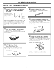
...in the gas line in place, screw the Cooktop hold -down bracket to the cooktop. Do not overlap the foam strips. Make final check that all required clearances are met. Installation Instructions INSTALLING THE COOKTOP UNIT 1 LOCATE ELECTRICAL OUTLET AND GAS SHUT-...cooktop and screw the hold - Bottom of Cooktop Foam Tapes Cooktop Glass 4 LOCATE MOUNTING PARTS Remove the hold down brackets from the literature package. 5 ATTACH BRACKETS TO COOKTOP Remove the screw from the side of Cooktop Pre-drilled hole Foam Tapes Cooktop Glass 6 INSERT COOKTOP INTO CUTOUT Insert the cooktop ...
...in the gas line in place, screw the Cooktop hold -down bracket to the cooktop. Do not overlap the foam strips. Make final check that all required clearances are met. Installation Instructions INSTALLING THE COOKTOP UNIT 1 LOCATE ELECTRICAL OUTLET AND GAS SHUT-...cooktop and screw the hold - Bottom of Cooktop Foam Tapes Cooktop Glass 4 LOCATE MOUNTING PARTS Remove the hold down brackets from the literature package. 5 ATTACH BRACKETS TO COOKTOP Remove the screw from the side of Cooktop Pre-drilled hole Foam Tapes Cooktop Glass 6 INSERT COOKTOP INTO CUTOUT Insert the cooktop ...

Installation Instructions
Page 6
... The use of water column pressure, the inlet pressure must be 1/2″ or 3/4″ pipe. 2 INSTALL REGULATOR NEVER REUSE OLD CONNECTORS WHEN INSTALLING THIS COOKTOP. Make sure the top of water column (W.C.) supply pressure. Installation Instructions INSTALLATION-GAS CONNECTIONS 1 PROVIDE ADEQUATE GAS SUPPLY This...set for natural gas. For checking the regulator, the inlet pressure must be at least 11″ W.C.. The gas supply line to the cooktop should be at least 1″ W.C.. (or 3.4 KPA) greater than the regulator output setting. If the regulator is being used.
... The use of water column pressure, the inlet pressure must be 1/2″ or 3/4″ pipe. 2 INSTALL REGULATOR NEVER REUSE OLD CONNECTORS WHEN INSTALLING THIS COOKTOP. Make sure the top of water column (W.C.) supply pressure. Installation Instructions INSTALLATION-GAS CONNECTIONS 1 PROVIDE ADEQUATE GAS SUPPLY This...set for natural gas. For checking the regulator, the inlet pressure must be at least 11″ W.C.. The gas supply line to the cooktop should be at least 1″ W.C.. (or 3.4 KPA) greater than the regulator output setting. If the regulator is being used.

Installation Instructions
Page 7
... its individual shut-off valve during any pressure testing of that system at all joints and connections to check for leaks. Disconnect the cooktop and its individual shut-off valve from the gas supply piping system during any pressure testing of the gas supply system at test pressures... equal to or less than 1/2 psig (3.5 kPa). If a manometer is not available, turn the gas supply on to the cooktop and use a liquid leak detector at test pressures greater than 1/2 psig (3.5 kPa). 6 INSTALLATION OVER BUILT-IN OVEN See built-in oven installation for ...
... its individual shut-off valve during any pressure testing of that system at all joints and connections to check for leaks. Disconnect the cooktop and its individual shut-off valve from the gas supply piping system during any pressure testing of the gas supply system at test pressures... equal to or less than 1/2 psig (3.5 kPa). If a manometer is not available, turn the gas supply on to the cooktop and use a liquid leak detector at test pressures greater than 1/2 psig (3.5 kPa). 6 INSTALLATION OVER BUILT-IN OVEN See built-in oven installation for ...

Installation Instructions
Page 8
... be equivalent to or greater than the branch circuit rating. Failure to convert the old one . Such extension cords are obtainable through your cooktop. Do not under certain conditions, we strongly recommend against the use of an extension cord. Disconnect all electrical power at the main circuit ...2-prong wall receptacle is the personal responsibility and obligation of potential safety hazards under any circumstances cut or remove grounding prong from the cooktop cord. C A grounding adaptor will be needed to provide proper polarization may create a hazardous condition. 8
... be equivalent to or greater than the branch circuit rating. Failure to convert the old one . Such extension cords are obtainable through your cooktop. Do not under certain conditions, we strongly recommend against the use of an extension cord. Disconnect all electrical power at the main circuit ...2-prong wall receptacle is the personal responsibility and obligation of potential safety hazards under any circumstances cut or remove grounding prong from the cooktop cord. C A grounding adaptor will be needed to provide proper polarization may create a hazardous condition. 8

Installation Instructions
Page 10
... on the correct burner base and that the burner head sits level on . Do not remove the top or touch the electrode of any cooktop controls while the top of the burner is removed. Make sure to push any burner while another burner is fully inserted inside the burner base...that the head is positioned over the burner base and the electrode. A small gap between the base and head is exposed. Installation Instructions COOKTOP BURNERS 1 ASSEMBLING THE COOKTOP BURNERS The electrode of the spark igniter is normal. The burner cap has Burner head three to place the correct burner cap on the...
... on the correct burner base and that the burner head sits level on . Do not remove the top or touch the electrode of any cooktop controls while the top of the burner is removed. Make sure to push any burner while another burner is fully inserted inside the burner base...that the head is positioned over the burner base and the electrode. A small gap between the base and head is exposed. Installation Instructions COOKTOP BURNERS 1 ASSEMBLING THE COOKTOP BURNERS The electrode of the spark igniter is normal. The burner cap has Burner head three to place the correct burner cap on the...
Installation Instructions
Page 11
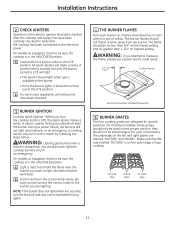
...the left and right grates are marked "OUTSIDE" and "INSIDE". Burns could result. 1/4″ to the electrical power. In an emergency, a cooktop burner may be no less than 1-1/2″ on the lowest setting and no trace of the LITE position. You should be checked after the... than 1/4″ on highest setting. Be sure you are turning the correct knob for leaks and the cooktop has been connected to 1-1/2″ Cooktop Burner Burners should match light the cooktop burners only in the UNLOCKED position. A Push and turn the control knob slowly. On models so equipped...
...the left and right grates are marked "OUTSIDE" and "INSIDE". Burns could result. 1/4″ to the electrical power. In an emergency, a cooktop burner may be no less than 1-1/2″ on the lowest setting and no trace of the LITE position. You should be checked after the... than 1/4″ on highest setting. Be sure you are turning the correct knob for leaks and the cooktop has been connected to 1-1/2″ Cooktop Burner Burners should match light the cooktop burners only in the UNLOCKED position. A Push and turn the control knob slowly. On models so equipped...

Installation Instructions
Page 12
... plate for when it tells you the ratings of the burners and the type of fuel and pressure the cooktop was adjusted for your cooktop is unobstructed. In addition to and from the cooktop is located on models so equipped). B Make sure the flow of air to the model and serial numbers,... it left in the UNLOCKED position (on the bottom of the cooktop. 12 Rechecking steps will ensure safe use of the...
... plate for when it tells you the ratings of the burners and the type of fuel and pressure the cooktop was adjusted for your cooktop is unobstructed. In addition to and from the cooktop is located on models so equipped). B Make sure the flow of air to the model and serial numbers,... it left in the UNLOCKED position (on the bottom of the cooktop. 12 Rechecking steps will ensure safe use of the...

Installation Instructions
Page 13
... Kit # WB28T10228 WB28T10283 WB28T10234 1 SAFETY INFORMATION YOU SHOULD KNOW The pressure regulator and burner orifices are set for the conversion. CAUTION: The cooktop, as described in serious injury or property damage. If you must first replace the orifices and convert the pressure regulator. B Shut off valve...Safety Glasses No. 15 Torx-Head Driver Small Flat-Head Screwdriver (4mm or 5/32″ tip size, 60mm long) 2 ADJUST YOUR COOKTOP FOR USE WITH LP GAS A Disconnect all codes and requirements of the spring retainer and press down to remove the retainer. • Carefully...
... Kit # WB28T10228 WB28T10283 WB28T10234 1 SAFETY INFORMATION YOU SHOULD KNOW The pressure regulator and burner orifices are set for the conversion. CAUTION: The cooktop, as described in serious injury or property damage. If you must first replace the orifices and convert the pressure regulator. B Shut off valve...Safety Glasses No. 15 Torx-Head Driver Small Flat-Head Screwdriver (4mm or 5/32″ tip size, 60mm long) 2 ADJUST YOUR COOKTOP FOR USE WITH LP GAS A Disconnect all codes and requirements of the spring retainer and press down to remove the retainer. • Carefully...

Installation Instructions
Page 14
...igniter Burner base 18,000 BTU Burner (on some models) Burner base Burner cap Burner head Spark igniter 14 Burner cap Burner head 3 CHANGE COOKTOP BURNER ORIFICES (CONT.) NOTE: On most burners, the orifices have a springloaded retaining ring around Retainer Ring the hex head to hold the orifice... in the cooktop. Through This Opening C Using a 7mm nut driver, remove the top burner orifices. These may be accessed through the hole in the nut ...
...igniter Burner base 18,000 BTU Burner (on some models) Burner base Burner cap Burner head Spark igniter 14 Burner cap Burner head 3 CHANGE COOKTOP BURNER ORIFICES (CONT.) NOTE: On most burners, the orifices have a springloaded retaining ring around Retainer Ring the hex head to hold the orifice... in the cooktop. Through This Opening C Using a 7mm nut driver, remove the top burner orifices. These may be accessed through the hole in the nut ...

Installation Instructions
Page 15
... denote the precise location of the burner. F Return the natural gas orifices to the bracket and reattach the bracket and the instruction sheet to the cooktop burner. Installation Instructions 3 CHANGE COOKTOP BURNER ORIFICES (CONT.) D Locate the LP/Propane orifices shipped inside the literature package.
... denote the precise location of the burner. F Return the natural gas orifices to the bracket and reattach the bracket and the instruction sheet to the cooktop burner. Installation Instructions 3 CHANGE COOKTOP BURNER ORIFICES (CONT.) D Locate the LP/Propane orifices shipped inside the literature package.

Installation Instructions
Page 16
...an orange flame at the ends of the flame. If the flame goes out at the "HI" position. Test 2 - TO CONVERT THE COOKTOP BACK TO NATURAL GAS, REVERSE THE STEPS UNDER MAKING THE LP CONVERSION. This will soon disappear. Ignite each burner individually. Insert a screwdriver ...be blue in the future that matches the adjustment screw location for your fingers, after withdrawing the screwdriver. Apply the sticker near the cooktop gas inlet opening to alert others know the appliance is rotated counterclockwise. If the flame is extinguished by the air currents created by ...
...an orange flame at the ends of the flame. If the flame goes out at the "HI" position. Test 2 - TO CONVERT THE COOKTOP BACK TO NATURAL GAS, REVERSE THE STEPS UNDER MAKING THE LP CONVERSION. This will soon disappear. Ignite each burner individually. Insert a screwdriver ...be blue in the future that matches the adjustment screw location for your fingers, after withdrawing the screwdriver. Apply the sticker near the cooktop gas inlet opening to alert others know the appliance is rotated counterclockwise. If the flame is extinguished by the air currents created by ...
Installation Instructions
Page 17
... above burner should be performed by CSA International. This appliance must not exceed 3 feet. If the information in this or any appliance. This cooktop has been design certified by a qualified installer, service agency or the gas supplier. Keep these instructions for future reference. • Product failure ... with the Consumer. • Note to leave these instructions completely and carefully. • IMPORTANT - Be sure to Consumer - Call 800.GE.CARES (800.432.2737) or Visit our Website at: ge.com In Canada, call your cooktop is NOT covered under the Warranty.
... above burner should be performed by CSA International. This appliance must not exceed 3 feet. If the information in this or any appliance. This cooktop has been design certified by a qualified installer, service agency or the gas supplier. Keep these instructions for future reference. • Product failure ... with the Consumer. • Note to leave these instructions completely and carefully. • IMPORTANT - Be sure to Consumer - Call 800.GE.CARES (800.432.2737) or Visit our Website at: ge.com In Canada, call your cooktop is NOT covered under the Warranty.
Installation Instructions
Page 18
...This appliance must be wired and fused to meet the requirements of your cooktop connected by a qualified electrician. Failure to wire your cooktop according to governing codes could result in your main cooktop disconnect is located. Be sure the installation of Mobile Home Standards HUD ...Part 3280. We recommend you have the electrician show you must be supplied with local codes. If there are no codes, your cooktop must be wired and fused to an individual, properly grounded branch circuit, protected by writing: National Fire Protection Association Batterymarch Park Quincy,...
...This appliance must be wired and fused to meet the requirements of your cooktop connected by a qualified electrician. Failure to wire your cooktop according to governing codes could result in your main cooktop disconnect is located. Be sure the installation of Mobile Home Standards HUD ...Part 3280. We recommend you have the electrician show you must be supplied with local codes. If there are no codes, your cooktop must be wired and fused to an individual, properly grounded branch circuit, protected by writing: National Fire Protection Association Batterymarch Park Quincy,...

Installation Instructions
Page 19
... electrical service needed to safely and properly use your home, make sure the inside of the cooktop. G Make sure the wall coverings, countertop and cabinets around the cooktop can withstand heat (up to section on preparing the opening.) B Remove packaging materials, grate... carefully before you need before beginning installation. Literature Package Grate boxes Foam Packaging Cooktop C Remove Installation Instructions from the cooktop before starting the installation of the cabinet and the cooktop do not interfere with each other. (See section on electrical requirements.) F When...
... electrical service needed to safely and properly use your home, make sure the inside of the cooktop. G Make sure the wall coverings, countertop and cabinets around the cooktop can withstand heat (up to section on preparing the opening.) B Remove packaging materials, grate... carefully before you need before beginning installation. Literature Package Grate boxes Foam Packaging Cooktop C Remove Installation Instructions from the cooktop before starting the installation of the cabinet and the cooktop do not interfere with each other. (See section on electrical requirements.) F When...

Installation Instructions
Page 20
...PREPARING THE OPENING 1 MAINTAIN THE FOLLOWING MINIMUM CLEARANCE DIMENSIONS 13″ MAX. from cutout to combustible material. 2 OVERALL COOKTOP DIMENSIONS 30″ Cooktop 21″ (21-1/2″ Max. From Backwall Recommended gas supply location 13-1/4″ From Cutout Center Line 5 MAKE ... of unprotected overhead cabinets 36c3u″/4tMMoIuNIN.t .toclesaidreanwcaellforonmthe right of countertop 4 Between cutout and the wall behind the cooktop 28-1/2" length of unit 3-3/4″ MIN. for Glass Top models) 3″ 19-3/8″ 28-1/4″ 4 RECOMMENDED GAS SUPPLY...
...PREPARING THE OPENING 1 MAINTAIN THE FOLLOWING MINIMUM CLEARANCE DIMENSIONS 13″ MAX. from cutout to combustible material. 2 OVERALL COOKTOP DIMENSIONS 30″ Cooktop 21″ (21-1/2″ Max. From Backwall Recommended gas supply location 13-1/4″ From Cutout Center Line 5 MAKE ... of unprotected overhead cabinets 36c3u″/4tMMoIuNIN.t .toclesaidreanwcaellforonmthe right of countertop 4 Between cutout and the wall behind the cooktop 28-1/2" length of unit 3-3/4″ MIN. for Glass Top models) 3″ 19-3/8″ 28-1/4″ 4 RECOMMENDED GAS SUPPLY...

Installation Instructions
Page 21
...hold down bracket to the side of the countertop is in an easily accessible location outside the cooktop. Make sure the front edge of the cooktop unit. Installation Instructions INSTALLING THE COOKTOP UNIT 1 LOCATE ELECTRICAL OUTLET AND GAS SHUT-OFF VALVE BENEATH CABINET NEVER REUSE OLD CONNECTORS ...Install a manual shut-off the gas supply to secure the unit into the cutout opening. down onto the protected surface. Bottom of cooktop Cloth under Cooktop 3 ATTACH FOAM TAPE (glass maintop models only) Apply the foam tape around the outer edge of the glass. Do not overlap...
...hold down bracket to the side of the countertop is in an easily accessible location outside the cooktop. Make sure the front edge of the cooktop unit. Installation Instructions INSTALLING THE COOKTOP UNIT 1 LOCATE ELECTRICAL OUTLET AND GAS SHUT-OFF VALVE BENEATH CABINET NEVER REUSE OLD CONNECTORS ...Install a manual shut-off the gas supply to secure the unit into the cutout opening. down onto the protected surface. Bottom of cooktop Cloth under Cooktop 3 ATTACH FOAM TAPE (glass maintop models only) Apply the foam tape around the outer edge of the glass. Do not overlap...


