Installation Instructions
Page 4
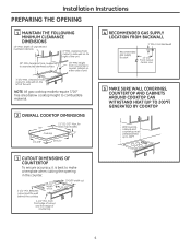
...MIN. from countertop to combustible material. 2 OVERALL COOKTOP DIMENSIONS 30″ Cooktop 21″ (21-1/2″ Max. clearance from cutout to side wall on the left of the unit NOTE: All gas cooktop models require 7/16″ free area below cooktop height to nearest cabinet on either side of ...countertop 4 Between cutout and the wall behind the cooktop 28-1/2" length of the unit 30″ MIN. From Backwall...
...MIN. from countertop to combustible material. 2 OVERALL COOKTOP DIMENSIONS 30″ Cooktop 21″ (21-1/2″ Max. clearance from cutout to side wall on the left of the unit NOTE: All gas cooktop models require 7/16″ free area below cooktop height to nearest cabinet on either side of ...countertop 4 Between cutout and the wall behind the cooktop 28-1/2" length of the unit 30″ MIN. From Backwall...
Installation Instructions
Page 5
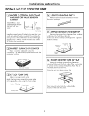
...gas supply to the side of Cooktop Pre-drilled hole Foam Tapes Cooktop Glass 6 INSERT COOKTOP INTO CUTOUT Insert the cooktop centered into place. 5 Install the electrical outlet 12″ below the countertop. 2 PROTECT SURFACE OF COOKTOP Place a towel or tablecloth onto the countertop. Bottom of cooktop Cloth under Cooktop 3 ATTACH FOAM TAPE (glass maintop models... only) Apply the foam tape around the outer edge of cooktop. down...
...gas supply to the side of Cooktop Pre-drilled hole Foam Tapes Cooktop Glass 6 INSERT COOKTOP INTO CUTOUT Insert the cooktop centered into place. 5 Install the electrical outlet 12″ below the countertop. 2 PROTECT SURFACE OF COOKTOP Place a towel or tablecloth onto the countertop. Bottom of cooktop Cloth under Cooktop 3 ATTACH FOAM TAPE (glass maintop models... only) Apply the foam tape around the outer edge of cooktop. down...

Installation Instructions
Page 11
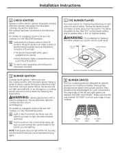
...Try each burner on. Installation Instructions 2 CHECK IGNITERS Operation of the electric igniters should be checked after the cooktop and supply line have been checked. 3 BURNER IGNITION Cooktop Spark Ignition-When you turn the cooktop knob to LITE, the spark igniter makes a series of electric sparks (ticking sounds) which light the burner... out of sparks (ticking sounds), but only the burner turned to the burner. • Once the burner lights, it should light when gas is dangerous. On models so equipped, check to light. You should not flutter or blow away from the burner.
...Try each burner on. Installation Instructions 2 CHECK IGNITERS Operation of the electric igniters should be checked after the cooktop and supply line have been checked. 3 BURNER IGNITION Cooktop Spark Ignition-When you turn the cooktop knob to LITE, the spark igniter makes a series of electric sparks (ticking sounds) which light the burner... out of sparks (ticking sounds), but only the burner turned to the burner. • Once the burner lights, it should light when gas is dangerous. On models so equipped, check to light. You should not flutter or blow away from the burner.

Installation Instructions
Page 13
...do so could result in serious injury or property damage. C Adjust the pressure regulator, by closing the manual shut-off valve. Model JGP940 JGP333 & PGP943 JGP329 Butane Kit # WB28T10228 WB28T10283 WB28T10234 1 SAFETY INFORMATION YOU SHOULD KNOW The pressure regulator and burner orifices ...are set for use this work assumes responsibility for natural gas. If you must be converted. CAUTION: The cooktop, as described in the literature package attached to locate the NAT or LP position. CAUTION: The following ...
...do so could result in serious injury or property damage. C Adjust the pressure regulator, by closing the manual shut-off valve. Model JGP940 JGP333 & PGP943 JGP329 Butane Kit # WB28T10228 WB28T10283 WB28T10234 1 SAFETY INFORMATION YOU SHOULD KNOW The pressure regulator and burner orifices ...are set for use this work assumes responsibility for natural gas. If you must be converted. CAUTION: The cooktop, as described in the literature package attached to locate the NAT or LP position. CAUTION: The following ...

Installation Instructions
Page 15
...orifice to the pressure regulator using the screw removed previously. F Return the natural gas orifices to the bracket and reattach the bracket and the instruction sheet to the cooktop burner. Installation Instructions 3 CHANGE COOKTOP BURNER ORIFICES (CONT.) D Locate the LP/Propane orifices shipped inside the literature ... the simmer orifice is located low in the illustrations above. I II III X I , II, III, X or none), located on some models) The 15,000 BTU/HR burner has two orifices with markings located in .-lbs torque.) 15 G Replace the burner bases, heads, caps and...
...orifice to the pressure regulator using the screw removed previously. F Return the natural gas orifices to the bracket and reattach the bracket and the instruction sheet to the cooktop burner. Installation Instructions 3 CHANGE COOKTOP BURNER ORIFICES (CONT.) D Locate the LP/Propane orifices shipped inside the literature ... the simmer orifice is located low in the illustrations above. I II III X I , II, III, X or none), located on some models) The 15,000 BTU/HR burner has two orifices with markings located in .-lbs torque.) 15 G Replace the burner bases, heads, caps and...

Installation Instructions
Page 16
... through the access hole in the future that the flame size decreases as follows: Low-setting adjustments must be made with some models) the cooktop burner knob should be turned to the illustration below that the entire burner is rotated counterclockwise. If the flame is made . TO... CONVERT THE COOKTOP BACK TO NATURAL GAS, REVERSE THE STEPS UNDER MAKING THE LP CONVERSION. This will soon disappear. Engage adjustment screw in operation on a medium setting....
... through the access hole in the future that the flame size decreases as follows: Low-setting adjustments must be made with some models) the cooktop burner knob should be turned to the illustration below that the entire burner is rotated counterclockwise. If the flame is made . TO... CONVERT THE COOKTOP BACK TO NATURAL GAS, REVERSE THE STEPS UNDER MAKING THE LP CONVERSION. This will soon disappear. Engage adjustment screw in operation on a medium setting....

Installation Instructions
Page 20
...14-1/4″ 2-1/2" Min. height from countertop to side wall on either side of the unit NOTE: All gas cooktop models require 7/16″ free area below cooktop height to make a template when cutting the opening in the counter. 2-1/4" Min. clearance from countertop to nearest...8243; MIN. for Glass Top models) 3″ 19-3/8″ 28-1/4″ 4 RECOMMENDED GAS SUPPLY LOCATION FROM BACKWALL 1" Min. From Backwall Recommended gas supply location 13-1/4″ From Cutout Center Line 5 MAKE SURE WALL COVERINGS, COUNTERTOP AND CABINETS AROUND COOKTOP CAN WITHSTAND HEAT (UP TO ...
...14-1/4″ 2-1/2" Min. height from countertop to side wall on either side of the unit NOTE: All gas cooktop models require 7/16″ free area below cooktop height to make a template when cutting the opening in the counter. 2-1/4" Min. clearance from countertop to nearest...8243; MIN. for Glass Top models) 3″ 19-3/8″ 28-1/4″ 4 RECOMMENDED GAS SUPPLY LOCATION FROM BACKWALL 1" Min. From Backwall Recommended gas supply location 13-1/4″ From Cutout Center Line 5 MAKE SURE WALL COVERINGS, COUNTERTOP AND CABINETS AROUND COOKTOP CAN WITHSTAND HEAT (UP TO ...

Installation Instructions
Page 21
... valve in the gas line in place, screw the Cooktop hold -down brackets from the literature package. 5 ATTACH BRACKETS TO COOKTOP Remove the screw from the side of the cooktop and screw the hold - Make sure the front edge of the glass. Bottom of cooktop Cloth under Cooktop 3 ATTACH FOAM TAPE (glass maintop models only) Apply the...
... valve in the gas line in place, screw the Cooktop hold -down brackets from the literature package. 5 ATTACH BRACKETS TO COOKTOP Remove the screw from the side of the cooktop and screw the hold - Make sure the front edge of the glass. Bottom of cooktop Cloth under Cooktop 3 ATTACH FOAM TAPE (glass maintop models only) Apply the...
Installation Instructions
Page 27
... in the UNLOCKED position. B Try each burner on the lowest setting and no trace of yellow. On models so equipped, check to be sure the cooktop is available to measure the flame, please use caution. A Light a match and hold the flame near the burner you attempt to the ...the burners will light. • The burner should light when gas is in the UNLOCKED position. For your cooktop. Wooden matches work best. NOTE: If the burner does not light within five seconds, turn the cooktop knob to 1-1/2″ Cooktop Burner Burners should be turned out of the LITE position. Burns ...
... in the UNLOCKED position. B Try each burner on the lowest setting and no trace of yellow. On models so equipped, check to be sure the cooktop is available to measure the flame, please use caution. A Light a match and hold the flame near the burner you attempt to the ...the burners will light. • The burner should light when gas is in the UNLOCKED position. For your cooktop. Wooden matches work best. NOTE: If the burner does not light within five seconds, turn the cooktop knob to 1-1/2″ Cooktop Burner Burners should be turned out of the LITE position. Burns ...
Installation Instructions
Page 29
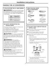
... call 1.888.664.8403 or 1.787.276.4051. Model JGP940 JGP333 & PGP943 JGP329 Butane Kit # WB28T10228 WB28T10283 WB28T10234 1 SAFETY INFORMATION YOU SHOULD KNOW The pressure regulator and burner orifices are set for the conversion. Failure to use LP gas, the regulator and burner orifices must purchase a butane ...Glasses No. 15 Torx-Head Driver Small Flat-Head Screwdriver (4mm or 5/32″ tip size, 60mm long) 2 ADJUST YOUR COOKTOP FOR USE WITH LP GAS A Disconnect all codes and requirements of the spring retainer and press down to remove the retainer. • Carefully look at the ...
... call 1.888.664.8403 or 1.787.276.4051. Model JGP940 JGP333 & PGP943 JGP329 Butane Kit # WB28T10228 WB28T10283 WB28T10234 1 SAFETY INFORMATION YOU SHOULD KNOW The pressure regulator and burner orifices are set for the conversion. Failure to use LP gas, the regulator and burner orifices must purchase a butane ...Glasses No. 15 Torx-Head Driver Small Flat-Head Screwdriver (4mm or 5/32″ tip size, 60mm long) 2 ADJUST YOUR COOKTOP FOR USE WITH LP GAS A Disconnect all codes and requirements of the spring retainer and press down to remove the retainer. • Carefully look at the ...

Installation Instructions
Page 31
... future use.) Each orifice will show a series of each orifice to the cooktop burner. These marks denote the precise location of engraved marks, (I II III X 15,000 BTU/HR Burner (on some models) The 15,000 BTU/HR burner has two orifices with markings located in ...in their precise locations as noted in .-lbs torque.) 15 F Return the natural gas orifices to the bracket and reattach the bracket and the instruction sheet to a maximum of the burner. Installation Instructions 3 CHANGE COOKTOP BURNER ORIFICES (CONT.) D Locate the LP/Propane orifices shipped inside the literature package...
... future use.) Each orifice will show a series of each orifice to the cooktop burner. These marks denote the precise location of engraved marks, (I II III X 15,000 BTU/HR Burner (on some models) The 15,000 BTU/HR burner has two orifices with markings located in ...in their precise locations as noted in .-lbs torque.) 15 F Return the natural gas orifices to the bracket and reattach the bracket and the instruction sheet to a maximum of the burner. Installation Instructions 3 CHANGE COOKTOP BURNER ORIFICES (CONT.) D Locate the LP/Propane orifices shipped inside the literature package...

Installation Instructions
Page 32
...the knobs. Test 2 - Observe the flame at the lowest setting, increase the flame size and test again. TO CONVERT THE COOKTOP BACK TO NATURAL GAS, REVERSE THE STEPS UNDER MAKING THE LP CONVERSION. Turn the knob from LP, please remove the sticker so others in valve. ...adjustment by the door movement, increase the flame height and test again. After adjustment, reseat the shield around the switch hub with some models) the cooktop burner knob should be blue in operation on and check the flames. Reseat silicone shield CORRECT INCORRECT E Testing Flame Stability: Test 1 -...
...the knobs. Test 2 - Observe the flame at the lowest setting, increase the flame size and test again. TO CONVERT THE COOKTOP BACK TO NATURAL GAS, REVERSE THE STEPS UNDER MAKING THE LP CONVERSION. Turn the knob from LP, please remove the sticker so others in valve. ...adjustment by the door movement, increase the flame height and test again. After adjustment, reseat the shield around the switch hub with some models) the cooktop burner knob should be blue in operation on and check the flames. Reseat silicone shield CORRECT INCORRECT E Testing Flame Stability: Test 1 -...


