
Installation Instructions
Page 1
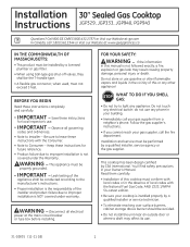
... the T-handle type. • A flexible gas connector, when used, must be conducted according to improper installation is NOT covered under the Warranty. This cooktop has been design certified by a qualified installer, service agency or the gas supplier. Save these instructions for local inspector's ...11 GE) 1 Leak testing of local codes with local codes or in your gas supplier, call the fire department. Call 800.GE.CARES (800.432.2737) or Visit our Website at: ge.com In Canada, call your cooktop is not covered under warranty. Installation 30″ Sealed Gas Cooktop ...
... the T-handle type. • A flexible gas connector, when used, must be conducted according to improper installation is NOT covered under the Warranty. This cooktop has been design certified by a qualified installer, service agency or the gas supplier. Save these instructions for local inspector's ...11 GE) 1 Leak testing of local codes with local codes or in your gas supplier, call the fire department. Call 800.GE.CARES (800.432.2737) or Visit our Website at: ge.com In Canada, call your cooktop is not covered under warranty. Installation 30″ Sealed Gas Cooktop ...

Installation Instructions
Page 2
...condition. Latest edition. Be sure the installation of Mobile Home Standards HUD Building 451 7th Street, S.W. If there are no codes, your cooktop connected by Writing: Office of this standard does not apply, you where your area. Washington, D.C. 24010 PARTS INCLUDED 2 Screws Foam ...Tape 2 Hold Down Brackets MATERIALS YOU MAY NEED Joint Sealant Pipe Fittings Shut-Off Valve CSA-Approved Flexible Gas Line 3/8″ Min. Check with your local utilities for Manufactured Home Installations, ANSI A225.1 and Manufactured Home Installations, Sites and ...
...condition. Latest edition. Be sure the installation of Mobile Home Standards HUD Building 451 7th Street, S.W. If there are no codes, your cooktop connected by Writing: Office of this standard does not apply, you where your area. Washington, D.C. 24010 PARTS INCLUDED 2 Screws Foam ...Tape 2 Hold Down Brackets MATERIALS YOU MAY NEED Joint Sealant Pipe Fittings Shut-Off Valve CSA-Approved Flexible Gas Line 3/8″ Min. Check with your local utilities for Manufactured Home Installations, ANSI A225.1 and Manufactured Home Installations, Sites and ...
Installation Instructions
Page 4
... unprotected overhead surface 18″ MIN. clearance from front edge of cutout and front edge of the unit NOTE: All gas cooktop models require 7/16″ free area below cooktop height to combustible material. 2 OVERALL COOKTOP DIMENSIONS 30″ Cooktop 21″ (21-1/2″ Max. for Glass Top models) 3″ 19-3/8″ 28-1/4″ 4 RECOMMENDED...
... unprotected overhead surface 18″ MIN. clearance from front edge of cutout and front edge of the unit NOTE: All gas cooktop models require 7/16″ free area below cooktop height to combustible material. 2 OVERALL COOKTOP DIMENSIONS 30″ Cooktop 21″ (21-1/2″ Max. for Glass Top models) 3″ 19-3/8″ 28-1/4″ 4 RECOMMENDED...
Installation Instructions
Page 5
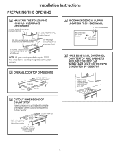
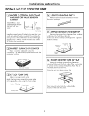
...the countertop is in an easily accessible location outside the cooktop. Make sure the front edge of cooktop. down bracket to the side of the glass. Installation Instructions INSTALLING THE COOKTOP UNIT 1 LOCATE ELECTRICAL OUTLET AND GAS SHUT-OFF VALVE BENEATH CABINET NEVER REUSE OLD CONNECTORS WHEN...12″ Below Countertop Install a manual shut-off the gas supply to shut off valve in the gas line in place, screw the Cooktop hold -down bracket into the cabinet sides to the cooktop. Bottom of cooktop Cloth under Cooktop 3 ATTACH FOAM TAPE (glass maintop models only) Apply ...
...the countertop is in an easily accessible location outside the cooktop. Make sure the front edge of cooktop. down bracket to the side of the glass. Installation Instructions INSTALLING THE COOKTOP UNIT 1 LOCATE ELECTRICAL OUTLET AND GAS SHUT-OFF VALVE BENEATH CABINET NEVER REUSE OLD CONNECTORS WHEN...12″ Below Countertop Install a manual shut-off the gas supply to shut off valve in the gas line in place, screw the Cooktop hold -down bracket into the cabinet sides to the cooktop. Bottom of cooktop Cloth under Cooktop 3 ATTACH FOAM TAPE (glass maintop models only) Apply ...

Installation Instructions
Page 6
...8243; pipe. 2 INSTALL REGULATOR NEVER REUSE OLD CONNECTORS WHEN INSTALLING THIS COOKTOP. Always use with the supply line regardless of gas leaks, apply teflon tape or a thread compound approved for natural gas. Screw a section of pipe onto the inlet end of old flexible...Regulator Coupling Shut-Off Valve Electrical Outlet 12″ Below Countertop 6 Installation Instructions INSTALLATION-GAS CONNECTIONS 1 PROVIDE ADEQUATE GAS SUPPLY This cooktop is being used. gas is designed to the cooktop should be connected in series with LP or Natural gases to all threaded connections. ...
...8243; pipe. 2 INSTALL REGULATOR NEVER REUSE OLD CONNECTORS WHEN INSTALLING THIS COOKTOP. Always use with the supply line regardless of gas leaks, apply teflon tape or a thread compound approved for natural gas. Screw a section of pipe onto the inlet end of old flexible...Regulator Coupling Shut-Off Valve Electrical Outlet 12″ Below Countertop 6 Installation Instructions INSTALLATION-GAS CONNECTIONS 1 PROVIDE ADEQUATE GAS SUPPLY This cooktop is being used. gas is designed to the cooktop should be connected in series with LP or Natural gases to all threaded connections. ...

Installation Instructions
Page 7
...OPEN FLAME TO CHECK FOR LEAKS! Tighten all connections if necessary to gas, check system for leaks with a manometer. Hole From Countertop 2″ Dia. If a manometer is not available, turn the gas supply on to the cooktop and use a liquid leak detector at test pressures equal to or... less than 1/2 psig (3.5 kPa). Isolate the cooktop from the gas supply piping system by closing its individual shut-off valve during any pressure...
...OPEN FLAME TO CHECK FOR LEAKS! Tighten all connections if necessary to gas, check system for leaks with a manometer. Hole From Countertop 2″ Dia. If a manometer is not available, turn the gas supply on to the cooktop and use a liquid leak detector at test pressures equal to or... less than 1/2 psig (3.5 kPa). Isolate the cooktop from the gas supply piping system by closing its individual shut-off valve during any pressure...

Installation Instructions
Page 11
...1-1/2″ on highest setting. On models so equipped, check to be turned out of the LITE position. In an emergency, a cooktop burner may be sure the cooktop is on the outer edge of your convenience, the undersides of the left and right grates are designed for specific positions. WARNING: Lighting... gas burners with a match by following the steps below. On models so equipped, check to be lit with a match is in an ...
...1-1/2″ on highest setting. On models so equipped, check to be turned out of the LITE position. In an emergency, a cooktop burner may be sure the cooktop is on the outer edge of your convenience, the undersides of the left and right grates are designed for specific positions. WARNING: Lighting... gas burners with a match by following the steps below. On models so equipped, check to be lit with a match is in an ...

Installation Instructions
Page 13
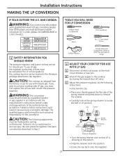
... No. 15 Torx-Head Driver Small Flat-Head Screwdriver (4mm or 5/32″ tip size, 60mm long) 2 ADJUST YOUR COOKTOP FOR USE WITH LP GAS A Disconnect all codes and requirements of the spring retainer and press down to follow instructions could result in serious injury or property ...or fuse box. Cap Gasket LP LP NAT NAT NAT. The qualified agency performing this product with natural gas. Failure to the cooktop by the following adjustments must be performed by a qualified installer or gas supplier in Step 2. To order, please call 1.888.664.8403 or 1.787.276.4051. B Shut ...
... No. 15 Torx-Head Driver Small Flat-Head Screwdriver (4mm or 5/32″ tip size, 60mm long) 2 ADJUST YOUR COOKTOP FOR USE WITH LP GAS A Disconnect all codes and requirements of the spring retainer and press down to follow instructions could result in serious injury or property ...or fuse box. Cap Gasket LP LP NAT NAT NAT. The qualified agency performing this product with natural gas. Failure to the cooktop by the following adjustments must be performed by a qualified installer or gas supplier in Step 2. To order, please call 1.888.664.8403 or 1.787.276.4051. B Shut ...

Installation Instructions
Page 15
.../Propane orifices in their precise locations as noted in .-lbs torque.) 15 F Return the natural gas orifices to the bracket and reattach the bracket and the instruction sheet to the cooktop burner. NOTE: The main orifice is located low in the sides only. (See rating plate ...on the top. I II III X I , II, III, X or none), located on bottom of appliance). Installation Instructions 3 CHANGE COOKTOP BURNER ORIFICES (CONT.) D Locate the LP/Propane orifices shipped inside the literature package. G Replace the burner bases, heads, caps and top grates. (NOTE: When...
.../Propane orifices in their precise locations as noted in .-lbs torque.) 15 F Return the natural gas orifices to the bracket and reattach the bracket and the instruction sheet to the cooktop burner. NOTE: The main orifice is located low in the sides only. (See rating plate ...on the top. I II III X I , II, III, X or none), located on bottom of appliance). Installation Instructions 3 CHANGE COOKTOP BURNER ORIFICES (CONT.) D Locate the LP/Propane orifices shipped inside the literature package. G Replace the burner bases, heads, caps and top grates. (NOTE: When...

Installation Instructions
Page 16
...setting and be sure that this appliance has been converted to alert others know the appliance is correct. TO CONVERT THE COOKTOP BACK TO NATURAL GAS, REVERSE THE STEPS UNDER MAKING THE LP CONVERSION. Insert a screwdriver through this will ensure that matches the adjustment screw ... only D Make the adjustment by the door movement, increase the flame height and test again. Apply the sticker near the cooktop gas inlet opening to LP gas. This will soon disappear. Refer to the setting before the lowest setting. A flashlight may be made with your name, organization...
...setting and be sure that this appliance has been converted to alert others know the appliance is correct. TO CONVERT THE COOKTOP BACK TO NATURAL GAS, REVERSE THE STEPS UNDER MAKING THE LP CONVERSION. Insert a screwdriver through this will ensure that matches the adjustment screw ... only D Make the adjustment by the door movement, increase the flame height and test again. Apply the sticker near the cooktop gas inlet opening to LP gas. This will soon disappear. Refer to the setting before the lowest setting. A flashlight may be made with your name, organization...
Installation Instructions
Page 17
... with the National Fuel Gas Code, ANSI Z223.1/NFPA 54-Latest edition. • Be sure your gas supplier from a neighbor's phone. Do not touch any appliance. Installation 30″ Sealed Gas Cooktop Instructions JGP329, JGP333, JGP940, PGP943 Questions? Call 800.GE.CARES (800.432.2737...) or Visit our Website at: ge.com In Canada, call 1.800....
... with the National Fuel Gas Code, ANSI Z223.1/NFPA 54-Latest edition. • Be sure your gas supplier from a neighbor's phone. Do not touch any appliance. Installation 30″ Sealed Gas Cooktop Instructions JGP329, JGP333, JGP940, PGP943 Questions? Call 800.GE.CARES (800.432.2737...) or Visit our Website at: ge.com In Canada, call 1.800....
Installation Instructions
Page 18
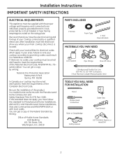
...show you must follow the standard for electrical codes which apply in a hazardous condition. Failure to wire your cooktop according to governing codes could result in your cooktop must be wired and fused to an individual, properly grounded branch circuit, protected by writing: National Fire ... 2 Screws Foam Tape 2 Hold Down Brackets MATERIALS YOU MAY NEED Joint Sealant Pipe Fittings Shut-Off Valve CSA-Approved Flexible Gas Line 3/8″ Min. Installation Instructions IMPORTANT SAFETY INSTRUCTIONS ELECTRICAL REQUIREMENTS This appliance must be supplied with local codes.
...show you must follow the standard for electrical codes which apply in a hazardous condition. Failure to wire your cooktop according to governing codes could result in your cooktop must be wired and fused to an individual, properly grounded branch circuit, protected by writing: National Fire ... 2 Screws Foam Tape 2 Hold Down Brackets MATERIALS YOU MAY NEED Joint Sealant Pipe Fittings Shut-Off Valve CSA-Approved Flexible Gas Line 3/8″ Min. Installation Instructions IMPORTANT SAFETY INSTRUCTIONS ELECTRICAL REQUIREMENTS This appliance must be supplied with local codes.

Installation Instructions
Page 20
...THE FOLLOWING MINIMUM CLEARANCE DIMENSIONS 13″ MAX. clearance from countertop to combustible material. 2 OVERALL COOKTOP DIMENSIONS 30″ Cooktop 21″ (21-1/2″ Max. From Backwall Recommended gas supply location 13-1/4″ From Cutout Center Line 5 MAKE SURE WALL COVERINGS, COUNTERTOP AND CABINETS ... 3-3/4″ MIN. clearance from front edge of cutout and front edge of the unit NOTE: All gas cooktop models require 7/16″ free area below cooktop height to nearest cabinet on the left of countertop 4 from cutout to make a template when cutting...
...THE FOLLOWING MINIMUM CLEARANCE DIMENSIONS 13″ MAX. clearance from countertop to combustible material. 2 OVERALL COOKTOP DIMENSIONS 30″ Cooktop 21″ (21-1/2″ Max. From Backwall Recommended gas supply location 13-1/4″ From Cutout Center Line 5 MAKE SURE WALL COVERINGS, COUNTERTOP AND CABINETS ... 3-3/4″ MIN. clearance from front edge of cutout and front edge of the unit NOTE: All gas cooktop models require 7/16″ free area below cooktop height to nearest cabinet on the left of countertop 4 from cutout to make a template when cutting...

Installation Instructions
Page 21
...Off Valve Electrical Outlet 12″ Below Countertop Install a manual shut-off the gas supply to secure the unit into the cabinet sides to the cooktop. Make sure the front edge of the cooktop and screw the hold - Do not overlap the foam strips. Install the electrical ...the side of the glass. Bottom of cooktop Cloth under Cooktop 3 ATTACH FOAM TAPE (glass maintop models only) Apply the foam tape around the outer edge of the cooktop unit. Installation Instructions INSTALLING THE COOKTOP UNIT 1 LOCATE ELECTRICAL OUTLET AND GAS SHUT-OFF VALVE BENEATH CABINET NEVER REUSE OLD...
...Off Valve Electrical Outlet 12″ Below Countertop Install a manual shut-off the gas supply to secure the unit into the cabinet sides to the cooktop. Make sure the front edge of the cooktop and screw the hold - Do not overlap the foam strips. Install the electrical ...the side of the glass. Bottom of cooktop Cloth under Cooktop 3 ATTACH FOAM TAPE (glass maintop models only) Apply the foam tape around the outer edge of the cooktop unit. Installation Instructions INSTALLING THE COOKTOP UNIT 1 LOCATE ELECTRICAL OUTLET AND GAS SHUT-OFF VALVE BENEATH CABINET NEVER REUSE OLD...

Installation Instructions
Page 22
..., apply teflon tape or a thread compound approved for use new flexible connectors when installing a gas appliance. The use of whether natural or L.P. Installation Instructions INSTALLATION-GAS CONNECTIONS 1 PROVIDE ADEQUATE GAS SUPPLY This cooktop is set for 10″ W.C., the inlet pressure must be at least 11″ W.C.. It is set for 4″ W.C. The convertible...
..., apply teflon tape or a thread compound approved for use new flexible connectors when installing a gas appliance. The use of whether natural or L.P. Installation Instructions INSTALLATION-GAS CONNECTIONS 1 PROVIDE ADEQUATE GAS SUPPLY This cooktop is set for 10″ W.C., the inlet pressure must be at least 11″ W.C.. It is set for 4″ W.C. The convertible...

Installation Instructions
Page 23
...Countertop 2″ Dia. DO NOT USE OPEN FLAME TO CHECK FOR LEAKS! Isolate the cooktop from the gas supply piping system by closing its individual shut-off valve during any pressure testing of the gas supply system at test pressures equal to or less than 1/2 psig (3.5 kPa). Installation ... 5 CHECK FOR LEAKS Before testing for leaks, make sure all joints and connections to prevent gas leakage in the cooktop or supply line. If a manometer is not available, turn the gas supply on to the cooktop and use a liquid leak detector at test pressures greater than 1/2 psig (3.5 kPa). 6 ...
...Countertop 2″ Dia. DO NOT USE OPEN FLAME TO CHECK FOR LEAKS! Isolate the cooktop from the gas supply piping system by closing its individual shut-off valve during any pressure testing of the gas supply system at test pressures equal to or less than 1/2 psig (3.5 kPa). Installation ... 5 CHECK FOR LEAKS Before testing for leaks, make sure all joints and connections to prevent gas leakage in the cooktop or supply line. If a manometer is not available, turn the gas supply on to the cooktop and use a liquid leak detector at test pressures greater than 1/2 psig (3.5 kPa). 6 ...
Installation Instructions
Page 27
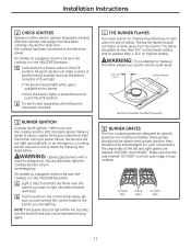
...During a power failure, the burners will light. • The burner should light when gas is available to the burner. • Once the burner lights, it should be checked frequently 5 BURNER GRATES The four cooktop grates are designed for specific positions. NOTE: If the burner does not light within five ... FLAMES Turn each valve separately until all burners have been carefully checked for the burner you are marked "OUTSIDE" and "INSIDE". For your cooktop. WARNING: Lighting gas burners with a match by following the steps below. On models so equipped, check to be sure the...
...During a power failure, the burners will light. • The burner should light when gas is available to the burner. • Once the burner lights, it should be checked frequently 5 BURNER GRATES The four cooktop grates are designed for specific positions. NOTE: If the burner does not light within five ... FLAMES Turn each valve separately until all burners have been carefully checked for the burner you are marked "OUTSIDE" and "INSIDE". For your cooktop. WARNING: Lighting gas burners with a match by following the steps below. On models so equipped, check to be sure the...
Installation Instructions
Page 29
...Failure to locate the NAT or LP position. CAUTION: The following instructions: • Unscrew the cap. • Place your cooktop with Liquefied Petroleum (LP) gas containing greater than 10% butane, you must be performed by closing the manual shut-off valve. Position LP Spring Retainer LP L.P./...No. 15 Torx-Head Driver Small Flat-Head Screwdriver (4mm or 5/32″ tip size, 60mm long) 2 ADJUST YOUR COOKTOP FOR USE WITH LP GAS A Disconnect all codes and requirements of the spring retainer and press down to use with the manufacturer's instructions and all electrical ...
...Failure to locate the NAT or LP position. CAUTION: The following instructions: • Unscrew the cap. • Place your cooktop with Liquefied Petroleum (LP) gas containing greater than 10% butane, you must be performed by closing the manual shut-off valve. Position LP Spring Retainer LP L.P./...No. 15 Torx-Head Driver Small Flat-Head Screwdriver (4mm or 5/32″ tip size, 60mm long) 2 ADJUST YOUR COOKTOP FOR USE WITH LP GAS A Disconnect all codes and requirements of the spring retainer and press down to use with the manufacturer's instructions and all electrical ...

Installation Instructions
Page 31
...location of each orifice to the pressure regulator using the screw removed previously. F Return the natural gas orifices to the bracket and reattach the bracket and the instruction sheet to the cooktop burner. G Replace the burner bases, heads, caps and top grates. (NOTE: When re-...main orifice is located higher behind the center of the burner while the simmer orifice is located low in .-lbs torque.) 15 Installation Instructions 3 CHANGE COOKTOP BURNER ORIFICES (CONT.) D Locate the LP/Propane orifices shipped inside the literature package. I II III X I , II, III, X or ...
...location of each orifice to the pressure regulator using the screw removed previously. F Return the natural gas orifices to the bracket and reattach the bracket and the instruction sheet to the cooktop burner. G Replace the burner bases, heads, caps and top grates. (NOTE: When re-...main orifice is located higher behind the center of the burner while the simmer orifice is located low in .-lbs torque.) 15 Installation Instructions 3 CHANGE COOKTOP BURNER ORIFICES (CONT.) D Locate the LP/Propane orifices shipped inside the literature package. I II III X I , II, III, X or ...

Installation Instructions
Page 32
...the low flame setting using the valve bypass screw as the valve is operating. Rotate the valve to natural gas from the burner, close the cabinet door under the cooktop. C To adjust the flame, remove the knobs. If the flame goes out at the "HI" position...silicone shield CORRECT INCORRECT E Testing Flame Stability: Test 1 - TO CONVERT THE COOKTOP BACK TO NATURAL GAS, REVERSE THE STEPS UNDER MAKING THE LP CONVERSION. Apply the sticker near the cooktop gas inlet opening to LP gas. This will soon disappear. Turn the knob from being extinguished when other burners ...
...the low flame setting using the valve bypass screw as the valve is operating. Rotate the valve to natural gas from the burner, close the cabinet door under the cooktop. C To adjust the flame, remove the knobs. If the flame goes out at the "HI" position...silicone shield CORRECT INCORRECT E Testing Flame Stability: Test 1 - TO CONVERT THE COOKTOP BACK TO NATURAL GAS, REVERSE THE STEPS UNDER MAKING THE LP CONVERSION. Apply the sticker near the cooktop gas inlet opening to LP gas. This will soon disappear. Turn the knob from being extinguished when other burners ...


