Gateway Quick Start Guide for Windows 7
Page 12
... to a monitor with a DVI (Digital Video Interface) port. Caution: If you want to store and transfer data by pressing the main power button on these devices. 2. Memory cards are used to use your television (or a speaker system). TV Tuner - Lets you must be required...disables any 12 - The computer requires a Gateway-certified adapter. Then switch ON your accounts at any built-in stereo headphones or powered speakers. The appropriate cable is not an 'full' IR port and can access and modify your computer by pressing the main power button. Note: Many monitors use a PC ...
... to a monitor with a DVI (Digital Video Interface) port. Caution: If you want to store and transfer data by pressing the main power button on these devices. 2. Memory cards are used to use your television (or a speaker system). TV Tuner - Lets you must be required...disables any 12 - The computer requires a Gateway-certified adapter. Then switch ON your accounts at any built-in stereo headphones or powered speakers. The appropriate cable is not an 'full' IR port and can access and modify your computer by pressing the main power button. Note: Many monitors use a PC ...
Gateway Quick Start Guide for Windows 7
Page 35
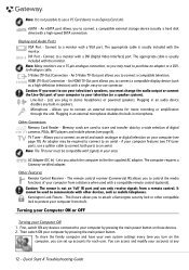
... menu. Disconnect all open programs, with the exception of the base and pull it , put the battery back, connect the power cable again and press the power button to turn on and wait for at least 15 minutes. 4. If it works. 2. Note that the battery is correctly inserted...additional internal hardware Internal hardware could be active. 1. d. Close all external devices from the wall socket, remove the battery and keep the power button pressed for at least ten seconds. 2. Then release it out. 2. Connect the AC adapter and attempt to change the screen saver ...
... menu. Disconnect all open programs, with the exception of the base and pull it , put the battery back, connect the power cable again and press the power button to turn on and wait for at least 15 minutes. 4. If it works. 2. Note that the battery is correctly inserted...additional internal hardware Internal hardware could be active. 1. d. Close all external devices from the wall socket, remove the battery and keep the power button pressed for at least ten seconds. 2. Then release it out. 2. Connect the AC adapter and attempt to change the screen saver ...

Gateway NV50 Series User's Reference Guide - Canada/French
Page 14
CHAPTER 2: Checking Out Your Notebook Right DVD drive USB port Modem Power jack button Component Icon Description USB port Plug a USB device (such as a diskette drive, flash drive, printer, scanner, camera, keyboard, or mouse) into this drive. DVD drive... more information, see "Using the DVD drive" on or off. For more information on page 44. Power button Press to those listed in "Identifying drive types" on configuring the power button mode, see "Connecting the optional dial-up modem cable into this port. Modem jack Plug a dial-up modem" on page 64. 8 You can also...
CHAPTER 2: Checking Out Your Notebook Right DVD drive USB port Modem Power jack button Component Icon Description USB port Plug a USB device (such as a diskette drive, flash drive, printer, scanner, camera, keyboard, or mouse) into this drive. DVD drive... more information, see "Using the DVD drive" on or off. For more information on page 44. Power button Press to those listed in "Identifying drive types" on configuring the power button mode, see "Connecting the optional dial-up modem cable into this port. Modem jack Plug a dial-up modem" on page 64. 8 You can also...

Gateway NV50 Series User's Reference Guide - Canada/French
Page 96
...your notebook. • Your notebook may not be experiencing some temporary memory problems. Shut down and restart your notebook is turned up. A dual-link cable is facing up, then try again. • Try a different disc. For more information about using your volume control, see "Adjusting the volume" ... the spindle so the retainers hold the disc in place. • Make sure that the Windows volume control is turned up. Press the power button. • The notebook may not be able to adjust the volume control in Sleep or Hibernate mode. Press FN + F4 several times ...
...your notebook. • Your notebook may not be experiencing some temporary memory problems. Shut down and restart your notebook is turned up. A dual-link cable is facing up, then try again. • Try a different disc. For more information about using your volume control, see "Adjusting the volume" ... the spindle so the retainers hold the disc in place. • Make sure that the Windows volume control is turned up. Press the power button. • The notebook may not be able to adjust the volume control in Sleep or Hibernate mode. Press FN + F4 several times ...

Gateway NV50 Series User's Reference Guide - Canada/French
Page 116
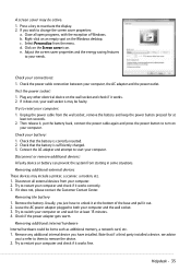
... the printer driver. Many printers have selected it is connected to work offline: 1 Click (Start), then click Control Panel. Press the button to put the printer online. • If the printer you want to press so the printer can start printing. To make sure that... click Set as Default Printer. • Reinstall the printer driver. CHAPTER 8: Troubleshooting The printer will not print • Check the cable between the printer and your printer for instructions on • Make sure that the power cable is not set a default printer: 1 Click (Start), then click Control Panel.
... the printer driver. Many printers have selected it is connected to work offline: 1 Click (Start), then click Control Panel. Press the button to put the printer online. • If the printer you want to press so the printer can start printing. To make sure that... click Set as Default Printer. • Reinstall the printer driver. CHAPTER 8: Troubleshooting The printer will not print • Check the cable between the printer and your printer for instructions on • Make sure that the power cable is not set a default printer: 1 Click (Start), then click Control Panel.
Gateway NV50 Series User's Reference Guide - Canada/French
Page 133
... jack 7 Increase volume 36 microphone jack 7 muting 35, 38 next button 31 pause button 31 play button 31 stop button 31 troubleshooting 113 audio CD cleaning 77 inserting 45, 46 automobile power adapter 60 B battery alternate power sources 60 bay 57 calibrating 76 changing 57 charge indicator 27, 56 charge...11 memory 10 Bluetooth system key 30 turning off 30, 41 turning on 30, 41 brightness adjusting 37 broadband modem connecting 20 C cable lock 7 cable modem 7, 20 connecting 20 troubleshooting 101 camera See digital camera Caps Lock indicator 26, 27 cards inserting memory card 47 memory card...
... jack 7 Increase volume 36 microphone jack 7 muting 35, 38 next button 31 pause button 31 play button 31 stop button 31 troubleshooting 113 audio CD cleaning 77 inserting 45, 46 automobile power adapter 60 B battery alternate power sources 60 bay 57 calibrating 76 changing 57 charge indicator 27, 56 charge...11 memory 10 Bluetooth system key 30 turning off 30, 41 turning on 30, 41 brightness adjusting 37 broadband modem connecting 20 C cable lock 7 cable modem 7, 20 connecting 20 troubleshooting 101 camera See digital camera Caps Lock indicator 26, 27 cards inserting memory card 47 memory card...

Gateway NV50 Series User's Reference Guide - English
Page 14
...the drive tray's plastic cover and compare the logo to turn the power on page 21. For more information on configuring the power button mode, see "Connecting the optional dial-up modem cable into this optional jack. Power button Press to those listed in "Identifying drive types" on page 44.... Modem jack Plug a dial-up modem" on or off. You can also configure the power button for Sleep/Resume ...
...the drive tray's plastic cover and compare the logo to turn the power on page 21. For more information on configuring the power button mode, see "Connecting the optional dial-up modem cable into this optional jack. Power button Press to those listed in "Identifying drive types" on page 44.... Modem jack Plug a dial-up modem" on or off. You can also configure the power button for Sleep/Resume ...

Gateway NV50 Series User's Reference Guide - English
Page 96
CHAPTER 8: Troubleshooting • Make sure the notebook is recommended for DVI output. A dual-link cable is not in Sleep or Hibernate mode. For more information about using your volume control, see "Cleaning CDs or DVDs" on page 77. You may ..., use shielded cables to connect to play these CDs on the tray, make sure that you place a disc on your notebook. • Make sure that the volume control on page 37. • Make sure that the CD label is facing up , then try again. • Try a different disc. Press the power button. •...
CHAPTER 8: Troubleshooting • Make sure the notebook is recommended for DVI output. A dual-link cable is not in Sleep or Hibernate mode. For more information about using your volume control, see "Cleaning CDs or DVDs" on page 77. You may ..., use shielded cables to connect to play these CDs on the tray, make sure that you place a disc on your notebook. • Make sure that the volume control on page 37. • Make sure that the CD label is facing up , then try again. • Try a different disc. Press the power button. •...

Service Guide
Page 23
...8482;cards. www.gateway.com Component Icon USB port Microphone jack Description Plug USB devices (such as a diskette drive, flash drive, printer, scanner, camera, keyboard, or mouse) into this port. Plug a dial-up modem cable into this jack. You can also configure the power button for Sleep/Resume mode.... 17 Press to turn the power on or off when speakers or headphones are turned off . Insert CDs or DVDs into ...
...8482;cards. www.gateway.com Component Icon USB port Microphone jack Description Plug USB devices (such as a diskette drive, flash drive, printer, scanner, camera, keyboard, or mouse) into this port. Plug a dial-up modem cable into this jack. You can also configure the power button for Sleep/Resume mode.... 17 Press to turn the power on or off when speakers or headphones are turned off . Insert CDs or DVDs into ...

Service Guide
Page 71
www.gateway.com 6 Turn the notebook over again so the palm rest is facing up. 7 Disconnect the LCD, webcam, and microphone cables from their system board connectors. 8 Release the LCD, webcam, and microphone cables from the palm rest. If there's no wireless card installed, proceed to step 11 to release the antenna cables from their latches. 9 If the notebook has a wireless card installed, note the antenna cable routing for later reference and then perform step 10 to disconnect the power button board cable. 65
www.gateway.com 6 Turn the notebook over again so the palm rest is facing up. 7 Disconnect the LCD, webcam, and microphone cables from their system board connectors. 8 Release the LCD, webcam, and microphone cables from the palm rest. If there's no wireless card installed, proceed to step 11 to release the antenna cables from their latches. 9 If the notebook has a wireless card installed, note the antenna cable routing for later reference and then perform step 10 to disconnect the power button board cable. 65
Service Guide
Page 72
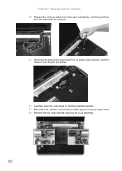
CHAPTER 3: Replacing notebook components 10 Release the antenna cables from their palm rest latches, and then pull them out from underneath the computer. 11 Disconnect the power button board cable from its system board connector, and then release it from its palm rest latches. 12 Carefully open the LCD panel to its fully extended position. 13 Move the LCD, webcam, and microphone cables away from the top hinge screws. 14 Remove the top hinge screws securing the LCD assembly. 66
CHAPTER 3: Replacing notebook components 10 Release the antenna cables from their palm rest latches, and then pull them out from underneath the computer. 11 Disconnect the power button board cable from its system board connector, and then release it from its palm rest latches. 12 Carefully open the LCD panel to its fully extended position. 13 Move the LCD, webcam, and microphone cables away from the top hinge screws. 14 Remove the top hinge screws securing the LCD assembly. 66
Service Guide
Page 73
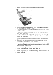
www.gateway.com 15 Lift the LCD panel assembly up and away from the notebook. 16 Position the new LCD panel assembly on the notebook, and then secure it to its system board connector. 20 Arrange the LCD, webcam, and microphone cables on page 62. 26 Reinstall the battery. 67 If...installed, proceed to step 19 to reconnect the power button board cable. 18 Refer to the antenna cable routing note made on step 9 and secure the antenna cables to the palm rest before pulling the ends downward to the wireless card compartment. 19 Arrange the power button cable on the palm rest and reconnect it with ...
www.gateway.com 15 Lift the LCD panel assembly up and away from the notebook. 16 Position the new LCD panel assembly on the notebook, and then secure it to its system board connector. 20 Arrange the LCD, webcam, and microphone cables on page 62. 26 Reinstall the battery. 67 If...installed, proceed to step 19 to reconnect the power button board cable. 18 Refer to the antenna cable routing note made on step 9 and secure the antenna cables to the palm rest before pulling the ends downward to the wireless card compartment. 19 Arrange the power button cable on the palm rest and reconnect it with ...
Service Guide
Page 103
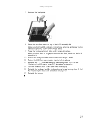
Make sure that the LCD, webcam, microphone, antenna, and power button cables are properly routed on the hinge sides. 9 Press the front panel on all sides until it snaps into place. www.gateway.com 7 Remove the front panel. 8 Place the new front panel on page 62. 15 Reinstall the battery. 97 Make sure that there...
Make sure that the LCD, webcam, microphone, antenna, and power button cables are properly routed on the hinge sides. 9 Press the front panel on all sides until it snaps into place. www.gateway.com 7 Remove the front panel. 8 Place the new front panel on page 62. 15 Reinstall the battery. 97 Make sure that there...

Service Guide
Page 112
... for later reference and then remove the board from the LCD assembly lid. 6 Disconnect the power button cable from the board. 7 Connect the power button cable to their places. 11 Reinstall the LCD front panel by performing steps 8-11 of the "Replacing the LCD front panel" procedure on page ...board should fit snugly against the spring to ensure proper contact when pressing the power button. 9 Place the LCD back on the LCD assembly lid. 10 Return the hinge screws to the new power button board. 8 Position the new power button board on the LCD assembly lid making sure it is facing up. 14 ...
... for later reference and then remove the board from the LCD assembly lid. 6 Disconnect the power button cable from the board. 7 Connect the power button cable to their places. 11 Reinstall the LCD front panel by performing steps 8-11 of the "Replacing the LCD front panel" procedure on page ...board should fit snugly against the spring to ensure proper contact when pressing the power button. 9 Place the LCD back on the LCD assembly lid. 10 Return the hinge screws to the new power button board. 8 Position the new power button board on the LCD assembly lid making sure it is facing up. 14 ...
Service Guide
Page 135
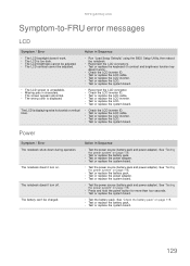
...cable. n Missing pels in Sequence n Test the power source (battery pack and power adapter). n The screen appears abnormal. n Reconnect the LCD connector. n Test or replace the LCD cable. n Test or replace the LCD inverter. n Test or replace the LCD cable. Power...inverter. See "Testing the power system" on page 118. n Test or replace the system board. n Press and hold the power button for more than four ...power adapter. n Test or replace the keyboard (if contrast and brightness function key doesn't work . n Test the battery pack. n Test or replace the LCD. www.gateway...
...cable. n Missing pels in Sequence n Test the power source (battery pack and power adapter). n The screen appears abnormal. n Reconnect the LCD connector. n Test or replace the LCD cable. n Test or replace the LCD inverter. n Test or replace the LCD cable. Power...inverter. See "Testing the power system" on page 118. n Test or replace the system board. n Press and hold the power button for more than four ...power adapter. n Test or replace the keyboard (if contrast and brightness function key doesn't work . n Test the battery pack. n Test or replace the LCD. www.gateway...

Service Guide
Page 142
CHAPTER 5: Connector locations System board layout Top view Item Code Component 1 MMB1 Multimedia board cable connector 2 AMIC1 Microphone cable connector 3 SPKR1 Speaker cable connector 4 LCD1 LCD cable connector 5 CCD1 Webcam board cable connector 6 PWRCN1 Power button board cable connector 7 USBCN1 USB board cable connector Item Code 8 KB1 9 ASB1 10 RTC1 11 MDC1 12 BT1 13 TPCN1 14 CARD1 Component Keyboard...
CHAPTER 5: Connector locations System board layout Top view Item Code Component 1 MMB1 Multimedia board cable connector 2 AMIC1 Microphone cable connector 3 SPKR1 Speaker cable connector 4 LCD1 LCD cable connector 5 CCD1 Webcam board cable connector 6 PWRCN1 Power button board cable connector 7 USBCN1 USB board cable connector Item Code 8 KB1 9 ASB1 10 RTC1 11 MDC1 12 BT1 13 TPCN1 14 CARD1 Component Keyboard...
Service Guide
Page 147
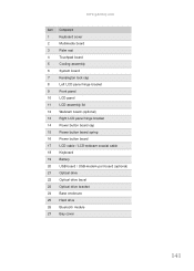
...gateway.com Item Component 1 Keyboard cover 2 Multimedia board 3 Palm rest 4 Touchpad board 5 Cooling assembly 6 System board 7 Kensington lock cap 8 Left LCD panel hinge bracket 9 Front panel 10 LCD panel 11 LCD assembly lid 12 Webcam board (optional) 13 Right LCD panel hinge bracket 14 Power button board cap 15 Power button board spring 16 Power button... board 17 LCD cable / LCD-webcam coaxial cable 18 Keyboard 19 Battery 20 USB board / USB-...
...gateway.com Item Component 1 Keyboard cover 2 Multimedia board 3 Palm rest 4 Touchpad board 5 Cooling assembly 6 System board 7 Kensington lock cap 8 Left LCD panel hinge bracket 9 Front panel 10 LCD panel 11 LCD assembly lid 12 Webcam board (optional) 13 Right LCD panel hinge bracket 14 Power button board cap 15 Power button board spring 16 Power button... board 17 LCD cable / LCD-webcam coaxial cable 18 Keyboard 19 Battery 20 USB board / USB-...

Service Guide
Page 151
... C.A. MMB FFC SJV50 JH 50.4BU07.011 C.A. www.gateway.com Category Cables Part Name BLUETOOTH BOARD CABLE BLUETOOTH BOARD CABLE POWER BUTTON BOARD CABLE POWER BUTTON BOARD CABLE LED LCD/CAMERA CABLE LED LCD/CAMERA CABLE USB BOARD CABLE USB BOARD CABLE MULTI-MEDIA BOARD CABLE MULTI-MEDIA BOARD CABLE MULTI-MEDIA BOARD CABLE MODEM CABLE TOUCHPAD BOARD CABLE TOUCHPAD BOARD CABLE Case / cover / bracket / assembly OPTICAL BRACKET HDD BRACKET...
... C.A. MMB FFC SJV50 JH 50.4BU07.011 C.A. www.gateway.com Category Cables Part Name BLUETOOTH BOARD CABLE BLUETOOTH BOARD CABLE POWER BUTTON BOARD CABLE POWER BUTTON BOARD CABLE LED LCD/CAMERA CABLE LED LCD/CAMERA CABLE USB BOARD CABLE USB BOARD CABLE MULTI-MEDIA BOARD CABLE MULTI-MEDIA BOARD CABLE MULTI-MEDIA BOARD CABLE MODEM CABLE TOUCHPAD BOARD CABLE TOUCHPAD BOARD CABLE Case / cover / bracket / assembly OPTICAL BRACKET HDD BRACKET...
Service Guide
Page 163
...navigate 29 Security menu 32 Bluetooth chipset 12 module, replace 83 system key 23 turning off 23 turning on 23 boot sequence 36 buttons specification 13 C cable lock 16 cable modem 16 capacitive touch keys 20, 24 Caps Lock indicator 21 card reader remove card 47 cards memory card slot 17 CD ... 95 LCD panel assembly 64 LCD panel hinge brackets 103 memory 50 microphone 109 modem 77 multimedia board 60 optical drive 56 palm rest 68 power button board 105 preparatory steps 47 processor 92 safety reminders 44 speakers 72 system board 86 tape 44 tools 46 touchpad / fingerprint reader board 74 ...
...navigate 29 Security menu 32 Bluetooth chipset 12 module, replace 83 system key 23 turning off 23 turning on 23 boot sequence 36 buttons specification 13 C cable lock 16 cable modem 16 capacitive touch keys 20, 24 Caps Lock indicator 21 card reader remove card 47 cards memory card slot 17 CD ... 95 LCD panel assembly 64 LCD panel hinge brackets 103 memory 50 microphone 109 modem 77 multimedia board 60 optical drive 56 palm rest 68 power button board 105 preparatory steps 47 processor 92 safety reminders 44 speakers 72 system board 86 tape 44 tools 46 touchpad / fingerprint reader board 74 ...
Service Guide
Page 165
www.gateway.com N navigation keys 22 network jack 16 O opening files 26 folders 26 programs ...16 Hybrid Sleep mode 22 indicator 19, 21 Sleep mode 22 status indicator 19, 21 power button board replace 105 power system check 118 battery pack 119 power adapter 118 PowerSave key 24 printer USB port 17 processor replace 92 Programmable key 24 programs ...blank 23 screen objects getting information 26 moving 26 selecting 25 scroll zone 25 security features BIOS passwords 33 Kensington cable lock 16 shortcut menus accessing 26 shortcuts opening menu 26 Sleep mode 22 system key 22 sound muting 24 ...
www.gateway.com N navigation keys 22 network jack 16 O opening files 26 folders 26 programs ...16 Hybrid Sleep mode 22 indicator 19, 21 Sleep mode 22 status indicator 19, 21 power button board replace 105 power system check 118 battery pack 119 power adapter 118 PowerSave key 24 printer USB port 17 processor replace 92 Programmable key 24 programs ...blank 23 screen objects getting information 26 moving 26 selecting 25 scroll zone 25 security features BIOS passwords 33 Kensington cable lock 16 shortcut menus accessing 26 shortcuts opening menu 26 Sleep mode 22 system key 22 sound muting 24 ...


