Gateway Desktop User's Guide
Page 4
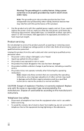
...• liquid was spilled into the product • the product was exposed to rain or water • the product has been dropped or the case has been damaged • the product exhibits a distinct change in use and/or before servicing. • To avoid the remote risk of electric ...supplied power supply cord set , make sure that are covered by the operating instructions, since improper adjustment of this product yourself, as opening or removing covers may expose you to qualified service personnel when: • the power cord or plug is not properly grounded may result in electric shock...
...• liquid was spilled into the product • the product was exposed to rain or water • the product has been dropped or the case has been damaged • the product exhibits a distinct change in use and/or before servicing. • To avoid the remote risk of electric ...supplied power supply cord set , make sure that are covered by the operating instructions, since improper adjustment of this product yourself, as opening or removing covers may expose you to qualified service personnel when: • the power cord or plug is not properly grounded may result in electric shock...
Gateway Desktop User's Guide
Page 16
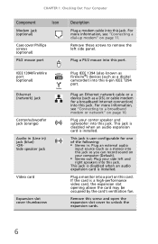
...the card may be occupied by the card's ventilation fan. Remove this port. This jack is installed. If the card is installed.... mouse into this screw and open the expansion slot cover to remove the left and right speakers into this card. Plug an Ethernet ...1394 port. CHAPTER 1: Checking Out Your Computer Component Icon Modem jack (optional) Case cover Phillips screws (optional) PS/2 mouse port IEEE 1394/FireWire port (optional) ...■ Stereo out: Plug your center speaker and subwoofer into this jack. Remove these screws to unlock the expansion cards. 6 For more information, see "...
...the card may be occupied by the card's ventilation fan. Remove this port. This jack is installed. If the card is installed.... mouse into this screw and open the expansion slot cover to remove the left and right speakers into this card. Plug an Ethernet ...1394 port. CHAPTER 1: Checking Out Your Computer Component Icon Modem jack (optional) Case cover Phillips screws (optional) PS/2 mouse port IEEE 1394/FireWire port (optional) ...■ Stereo out: Plug your center speaker and subwoofer into this jack. Remove these screws to unlock the expansion cards. 6 For more information, see "...
Gateway Desktop User's Guide
Page 57
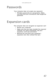
www.gateway.com Passwords Your computer does not accept your computer's expansion slot, then reinstall the card. 47 Expansion cards The computer does not recognize an expansion card • Restart your computer. • Make sure that CAPS LOCK is turned off, then retype the password. Make sure that you have installed the required software. For more information, see your expansion card's documentation. • Remove the card from your password • Windows passwords are case-sensitive.
www.gateway.com Passwords Your computer does not accept your computer's expansion slot, then reinstall the card. 47 Expansion cards The computer does not recognize an expansion card • Restart your computer. • Make sure that CAPS LOCK is turned off, then retype the password. Make sure that you have installed the required software. For more information, see your expansion card's documentation. • Remove the card from your password • Windows passwords are case-sensitive.
User Guide
Page 7
11 Maintaining Your Computer 161 Caring for your computer 162 Protecting your computer from viruses 164 Managing hard drive space 167 Checking hard drive space 167 ... Computer 189 Selecting a place to work 190 Gathering the tools you need 190 Preventing static electricity discharge 191 Opening the case 192 Removing the side panel 192 Removing the front bezel 195 Closing the case 196 Replacing the side panel 196 Replacing the front bezel 197 Adding or replacing a CD, DVD, or diskette drive...
11 Maintaining Your Computer 161 Caring for your computer 162 Protecting your computer from viruses 164 Managing hard drive space 167 Checking hard drive space 167 ... Computer 189 Selecting a place to work 190 Gathering the tools you need 190 Preventing static electricity discharge 191 Opening the case 192 Removing the side panel 192 Removing the front bezel 195 Closing the case 196 Replacing the side panel 196 Replacing the front bezel 197 Adding or replacing a CD, DVD, or diskette drive...

User Guide
Page 13
... into this port. The switch is supplied at a nominal 115 volts at 60 Hz. Plug a microphone, speakers, or headphones into these screws before opening the case. Plug a parallel device (such as a digital camera) into these ports. In the United States, the utility power is preset at 50 Hz. If your area..., scanner, or other peripheral device" on your optional modem has a telephone jack, plug the cable for your computer is operating in the United States. www.gateway.com 5 Thumbscrews Parallel port Ethernet (network) jack Telephone jack Remove these jacks.
... into this port. The switch is supplied at a nominal 115 volts at 60 Hz. Plug a microphone, speakers, or headphones into these screws before opening the case. Plug a parallel device (such as a digital camera) into these ports. In the United States, the utility power is preset at 50 Hz. If your area..., scanner, or other peripheral device" on your optional modem has a telephone jack, plug the cable for your computer is operating in the United States. www.gateway.com 5 Thumbscrews Parallel port Ethernet (network) jack Telephone jack Remove these jacks.

User Guide
Page 197
13 Upgrading Your Computer This chapter provides information about upgrading and replacing components in cards ■ Add memory ■ Change the battery ■ Replace system boards You must open the computer case to upgrade or replace components. Read this chapter to learn how to: ■ Open and close the computer case ■ Remove and install drives and components ■ Remove and install add-in your computer. If you are not comfortable with these procedures, get help from a more experienced computer user or computer service technician. 189
13 Upgrading Your Computer This chapter provides information about upgrading and replacing components in cards ■ Add memory ■ Change the battery ■ Replace system boards You must open the computer case to upgrade or replace components. Read this chapter to learn how to: ■ Open and close the computer case ■ Remove and install drives and components ■ Remove and install add-in your computer. If you are not comfortable with these procedures, get help from a more experienced computer user or computer service technician. 189
User Guide
Page 199
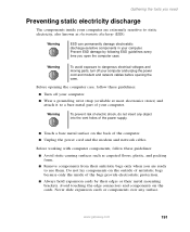
... metal part of your computer are ready to static electricity, also known as carpeted floors, plastic, and packing foam. ■ Remove components from their metal mounting brackets. Avoid touching the edge connectors and components on the outside of antistatic bags because only the inside... computer and unplug the power cord and modem and network cables before opening the computer case, follow these guidelines: ■ Turn off your computer. Before opening the case. www.gateway.com 191 Do not lay components on the cards. Never slide expansion cards or components...
... metal part of your computer are ready to static electricity, also known as carpeted floors, plastic, and packing foam. ■ Remove components from their metal mounting brackets. Avoid touching the edge connectors and components on the outside of antistatic bags because only the inside... computer and unplug the power cord and modem and network cables before opening the computer case, follow these guidelines: ■ Turn off your computer. Before opening the case. www.gateway.com 191 Do not lay components on the cards. Never slide expansion cards or components...
User Guide
Page 200
... panel To remove the side panel: 1 Follow the instructions in "Preventing static electricity discharge" on page 191. 2 Shut down your computer, then disconnect the power cord and modem, ... to drain any residual power from your computer, then unplug the power cord and modem cable before opening the case. Warning To avoid exposure to internal components. Chapter 11: Upgrading Your Computer Opening the case Your computer case provides easy access to dangerous electrical voltages and moving parts, turn off your computer. 192 www...
... panel To remove the side panel: 1 Follow the instructions in "Preventing static electricity discharge" on page 191. 2 Shut down your computer, then disconnect the power cord and modem, ... to drain any residual power from your computer, then unplug the power cord and modem cable before opening the case. Warning To avoid exposure to internal components. Chapter 11: Upgrading Your Computer Opening the case Your computer case provides easy access to dangerous electrical voltages and moving parts, turn off your computer. 192 www...
User Guide
Page 201
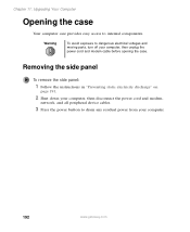
Opening the case Thumbscrew Thumbscrew www.gateway.com 193 4 Remove the two thumbscrews from the side panel cover.
Opening the case Thumbscrew Thumbscrew www.gateway.com 193 4 Remove the two thumbscrews from the side panel cover.

User Guide
Page 203
www.gateway.com 195 Removing the front bezel Opening the case To remove the front bezel: ■ Position the computer where you can grasp the front bottom edge of the bezel, then pull the bezel out and away from the case.
www.gateway.com 195 Removing the front bezel Opening the case To remove the front bezel: ■ Position the computer where you can grasp the front bottom edge of the bezel, then pull the bezel out and away from the case.
User Guide
Page 214
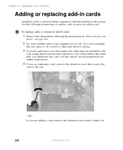
... retention screw from a blank slot. 206 www.gateway.com To replace, add, or reseat an add-in card: 1 Remove the side panel by following instructions to replace, add, or reseat an add-in the computer to add functionality to the case. - Use the following the instructions in card ...documentation for further instructions. 4 If you are replacing a card, remove the retention screw that secures the card to the system. Chapter 11: Upgrading Your Computer Adding or replacing add-in ...
... retention screw from a blank slot. 206 www.gateway.com To replace, add, or reseat an add-in card: 1 Remove the side panel by following instructions to replace, add, or reseat an add-in the computer to add functionality to the case. - Use the following the instructions in card ...documentation for further instructions. 4 If you are replacing a card, remove the retention screw that secures the card to the system. Chapter 11: Upgrading Your Computer Adding or replacing add-in ...

User Guide
Page 216
... replace DIMM memory: 1 Remove the side panel by following the instructions in "Removing the side panel" on its side. Chapter 11: Upgrading Your Computer Warning Do not touch the contacts on a towel or other non-abrasive surface. 208 www.gateway.com To avoid scratching the case, place it on the ...make sure that came with the retention screw. 9 If you install the correct type of the add-in "Closing the case" on page 196. 11 See the documentation that you disconnected any special software installation instructions. Touching the contacts can slightly seesaw the card end-to-end...
... replace DIMM memory: 1 Remove the side panel by following the instructions in "Removing the side panel" on its side. Chapter 11: Upgrading Your Computer Warning Do not touch the contacts on a towel or other non-abrasive surface. 208 www.gateway.com To avoid scratching the case, place it on the ...make sure that came with the retention screw. 9 If you install the correct type of the add-in "Closing the case" on page 196. 11 See the documentation that you disconnected any special software installation instructions. Touching the contacts can slightly seesaw the card end-to-end...
User Guide
Page 220
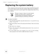
... by following the manufacturer's instructions. To avoid scratching the case, place it on a towel or other non-abrasive surface. 212 www.gateway.com Warning Danger of used batteries following the instructions in the... in "Using the BIOS Setup utility" on page 238. 2 Write down all the values in "Removing the side panel" on page 192. 5 For more stability, place your computer. Use a battery of... are not saved when you turn off your computer, replace the system battery. Chapter 11: Upgrading Your Computer Replacing the system battery If the computer clock does not keep time...
... by following the manufacturer's instructions. To avoid scratching the case, place it on a towel or other non-abrasive surface. 212 www.gateway.com Warning Danger of used batteries following the instructions in the... in "Using the BIOS Setup utility" on page 238. 2 Write down all the values in "Removing the side panel" on page 192. 5 For more stability, place your computer. Use a battery of... are not saved when you turn off your computer, replace the system battery. Chapter 11: Upgrading Your Computer Replacing the system battery If the computer clock does not keep time...

User Guide
Page 222
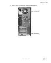
To avoid scratching the case, place it on its side. Chapter 11: Upgrading Your Computer Replacing the power supply To replace the power supply: 1 Remove the side panel by following the instructions in "Replacing the side panel" on page 196. 2 Place your computer on a towel or other non-abrasive surface. 3 Disconnect the power supply cables from all components (such as hard drives, CD or DVD drives, and the system board), noting their locations and orientation. (You will reconnect the cables after you install the new power supply.) 214 www.gateway.com
To avoid scratching the case, place it on its side. Chapter 11: Upgrading Your Computer Replacing the power supply To replace the power supply: 1 Remove the side panel by following the instructions in "Replacing the side panel" on page 196. 2 Place your computer on a towel or other non-abrasive surface. 3 Disconnect the power supply cables from all components (such as hard drives, CD or DVD drives, and the system board), noting their locations and orientation. (You will reconnect the cables after you install the new power supply.) 214 www.gateway.com
User Guide
Page 223
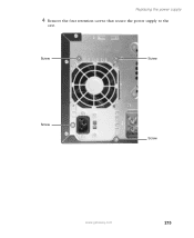
Screw Screw Screw Screw www.gateway.com 215 Replacing the power supply 4 Remove the four retention screws that secure the power supply to the case.
Screw Screw Screw Screw www.gateway.com 215 Replacing the power supply 4 Remove the four retention screws that secure the power supply to the case.

User Guide
Page 224
...abrasive surface. 3 Remove all of the add-in cards by following the instructions in "Closing the case" on page 196. Chapter 11: Upgrading Your Computer 5 Slide the power supply up and away from Step 3. See the power supply documentation for further instructions. 8 Close the case by following the ...supply to the case. 7 Reconnect the power supply cables using your computer on its side. Replacing the system board To replace the system board: 1 Remove the side panel by following the instructions in "Adding or replacing add-in "Removing the side panel" on page 206. 216 www.gateway.com
...abrasive surface. 3 Remove all of the add-in cards by following the instructions in "Closing the case" on page 196. Chapter 11: Upgrading Your Computer 5 Slide the power supply up and away from Step 3. See the power supply documentation for further instructions. 8 Close the case by following the ...supply to the case. 7 Reconnect the power supply cables using your computer on its side. Replacing the system board To replace the system board: 1 Remove the side panel by following the instructions in "Adding or replacing add-in "Removing the side panel" on page 206. 216 www.gateway.com
User Guide
Page 228
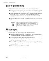
...drive is not full. 220 www.gateway.com Even if the power is extremely dangerous. Also, opening your computer and contact a qualified computer technician. Instead, unplug your computer case. First steps Try these safety guidelines: ■ Never remove your computer case cover while your computer is turned on... . ■ If a peripheral device (such as the keyboard or mouse) does not work, make sure that all connections are secure. ■ If you added or removed computer components before opening ...
...drive is not full. 220 www.gateway.com Even if the power is extremely dangerous. Also, opening your computer and contact a qualified computer technician. Instead, unplug your computer case. First steps Try these safety guidelines: ■ Never remove your computer case cover while your computer is turned on... . ■ If a peripheral device (such as the keyboard or mouse) does not work, make sure that all connections are secure. ■ If you added or removed computer components before opening ...
User Guide
Page 237
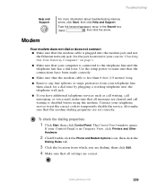
... that the connections have been made correctly. ■ Make sure that the modem cable is less than 6 feet (1.8 meters) long. ■ Remove any line splitters or surge protectors from your telephone line, then check for your telephone service to get the correct code to the telephone line... call messaging, or voice mail, make sure that all settings are set correctly. Contact your case in the Search box , then click the arrow. Type the keyword memory error in "Checking Out Your Gateway Computer" on page 1. ■ Make sure that the modem cable is connected to temporarily disable...
... that the connections have been made correctly. ■ Make sure that the modem cable is less than 6 feet (1.8 meters) long. ■ Remove any line splitters or surge protectors from your telephone line, then check for your telephone service to get the correct code to the telephone line... call messaging, or voice mail, make sure that all settings are set correctly. Contact your case in the Search box , then click the arrow. Type the keyword memory error in "Checking Out Your Gateway Computer" on page 1. ■ Make sure that the modem cable is connected to temporarily disable...
User Guide
Page 263
... MusicMatch 88 audio file streaming 141 audio in jack 5 AVI file 82 B background 125 backing up files 112, 173 battery replacing 212 bezel removing 195 replacing 197 BIOS Setup utility 238 broadband Internet connection 56, 140 browser Web 57, 59 browsing for files and folders 44 C cable modem... connecting 5 camera See digital camera See digital video camera Caps Lock indicator 19 capturing video 114 card installing and replacing 206 troubleshooting 222 case closing 196 opening 192 CD adding tracks to your library 93 cleaning 224 controlling play with keyboard 20 copying 98 creating audio 108 255
... MusicMatch 88 audio file streaming 141 audio in jack 5 AVI file 82 B background 125 backing up files 112, 173 battery replacing 212 bezel removing 195 replacing 197 BIOS Setup utility 238 broadband Internet connection 56, 140 browser Web 57, 59 browsing for files and folders 44 C cable modem... connecting 5 camera See digital camera See digital video camera Caps Lock indicator 19 capturing video 114 card installing and replacing 206 troubleshooting 222 case closing 196 opening 192 CD adding tracks to your library 93 cleaning 224 controlling play with keyboard 20 copying 98 creating audio 108 255
User Guide
Page 269
... out jack 5 links 59 M maintenance 161 backing up files 173 checking for drive errors 169 checking hard drive space 167 cleaning case 175 cleaning component exteriors 175 cleaning computer screen 176 cleaning keyboard 176 defragmenting 171 deleting files 168 suggested schedule 163 using Scheduled Task ...button 37 media card reader locating 3 locating drive 3 using 117 media cards adding 118 inserting 118 installing 118 media card slots 117 removing 118 replacing 118 Media Player 82 memory 9 installing and replacing 208 troubleshooting 228 memory card reader memory card types supported 117 menu ...
... out jack 5 links 59 M maintenance 161 backing up files 173 checking for drive errors 169 checking hard drive space 167 cleaning case 175 cleaning component exteriors 175 cleaning computer screen 176 cleaning keyboard 176 defragmenting 171 deleting files 168 suggested schedule 163 using Scheduled Task ...button 37 media card reader locating 3 locating drive 3 using 117 media cards adding 118 inserting 118 installing 118 media card slots 117 removing 118 replacing 118 Media Player 82 memory 9 installing and replacing 208 troubleshooting 228 memory card reader memory card types supported 117 menu ...


