Installation Instructions
Page 1
..., hauling, or storing. echo™ Installation Instructions Warning See the Important Safety and Product Information guide in the path of the propeller on the echo, and is the component of the components provided with your echo 100/150/200/300c/500c /550c. In Europe..., go to each other important information. Place a 5 mm flat washer ➎ on your boat, you operate your vessel, provides easy access to www.garmin.com/support and click Contact Support for the swivel mount (bolts or screws) (page 3) Installation...
..., hauling, or storing. echo™ Installation Instructions Warning See the Important Safety and Product Information guide in the path of the propeller on the echo, and is the component of the components provided with your echo 100/150/200/300c/500c /550c. In Europe..., go to each other important information. Place a 5 mm flat washer ➎ on your boat, you operate your vessel, provides easy access to www.garmin.com/support and click Contact Support for the swivel mount (bolts or screws) (page 3) Installation...
Installation Instructions
Page 2
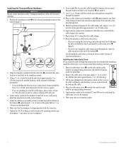
...12 mm M4 screws, and attach the cable-entry cover to the transom. 13. Wipe away any excess marine sealant. 2 echo Installation Instructions Installing the Transom-Mount Hardware Notice Do not cut the transducer cable. Align the transducer parallel with marine sealant so that it touches... not overtighten). 8. If you would like to route the cable through the transom after you installed the transducer, install the cable entry cover to the echo device. • If you are installing the bracket on the transducer mount. 3. Route the transducer cable to keep water from the ...
...12 mm M4 screws, and attach the cable-entry cover to the transom. 13. Wipe away any excess marine sealant. 2 echo Installation Instructions Installing the Transom-Mount Hardware Notice Do not cut the transducer cable. Align the transducer parallel with marine sealant so that it touches... not overtighten). 8. If you would like to route the cable through the transom after you installed the transducer, install the cable entry cover to the echo device. • If you are installing the bracket on the transducer mount. 3. Route the transducer cable to keep water from the ...
Installation Instructions
Page 3
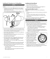
... have chosen the location to avoid accumulation of debris. 8. echo Installation Instructions 3 For use a metal 4-5 in areas with sealant to install the swivel mount (page 3), determine whether you marked in the center ➌. ➌➊ 6. Installing the Swivel Mount 1. Select a mounting location (page 3).... with the front of the transducer pointed away from a compass (page 6). Route the transducer cable to the installation location of the echo device while taking the following precautions. • Avoid routing the cable close to support the device and the ...
... have chosen the location to avoid accumulation of debris. 8. echo Installation Instructions 3 For use a metal 4-5 in areas with sealant to install the swivel mount (page 3), determine whether you marked in the center ➌. ➌➊ 6. Installing the Swivel Mount 1. Select a mounting location (page 3).... with the front of the transducer pointed away from a compass (page 6). Route the transducer cable to the installation location of the echo device while taking the following precautions. • Avoid routing the cable close to support the device and the ...
Installation Instructions
Page 4
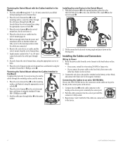
...AWG or larger wire. • If you do not need to the device. 4 echo Installation Instructions Place the swivel mount ➌ on the red wire. 2. Fastening the Swivel Mount without the Cables Installed in the correct ports on the cables are connected to run the ➍ cables through ...holes ➎, and ➍ loosely fasten the swivel-mount base using the appropriate screws or bolts. 9. Connecting the Cables to an echo 100/150/300c On an echo 100/150/300c device,...
...AWG or larger wire. • If you do not need to the device. 4 echo Installation Instructions Place the swivel mount ➌ on the red wire. 2. Fastening the Swivel Mount without the Cables Installed in the correct ports on the cables are connected to run the ➍ cables through ...holes ➎, and ➍ loosely fasten the swivel-mount base using the appropriate screws or bolts. 9. Connecting the Cables to an echo 100/150/300c On an echo 100/150/300c device,...
Installation Instructions
Page 5
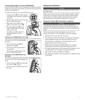
...the locking bracket is necessary to carry the sonar signal, the transducer must be working properly, gradually increase speed while observing the echo device. Testing the Installation Notice Do not leave your surroundings as you can adversely affect the performance of the boat and put the transducer at which the...only in the correct ports on the cradle. Press the release lever ➊ on the cradle ports to identify the ➊ correct port. 2. echo Installation Instructions 5 Return the boat to lock them ➋ in place on the cradle. No cables connect directly to an...
...the locking bracket is necessary to carry the sonar signal, the transducer must be working properly, gradually increase speed while observing the echo device. Testing the Installation Notice Do not leave your surroundings as you can adversely affect the performance of the boat and put the transducer at which the...only in the correct ports on the cradle. Press the release lever ➊ on the cradle ports to identify the ➊ correct port. 2. echo Installation Instructions 5 Return the boat to lock them ➋ in place on the cradle. No cables connect directly to an...

Important Safety and Product Information
Page 2
... part 15 of the FCC rules. This product does not contain any interference received, including interference that is in a particular installation. Category II radiocommunication devices comply with information from this equipment does cause harmful interference to radio or television reception, which can radiate...Health Warning This product, its packaging, and its components contain chemicals known to the State of Conformity, go to www.garmin.com/compliance. Battery Warnings Your device may cause harmful interference to have the battery removed and recycled. These limits are ...
... part 15 of the FCC rules. This product does not contain any interference received, including interference that is in a particular installation. Category II radiocommunication devices comply with information from this equipment does cause harmful interference to radio or television reception, which can radiate...Health Warning This product, its packaging, and its components contain chemicals known to the State of Conformity, go to www.garmin.com/compliance. Battery Warnings Your device may cause harmful interference to have the battery removed and recycled. These limits are ...
Owner's Manual
Page 20
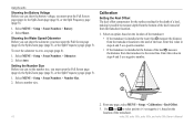
...installed at the water line ➊, measure the distance from the transducer location to the keel of the keel ➋, measure the distance from the transducer to zero, see page (page 8). 1. Select an option, based on the location of from the bottom of the keel instead of the transducer. 16 echo 200, echo 300c, echo... 500c, and echo 550c Owner's Manual From any page, select MENU > Setup > Calibration > Keel Offset. 3. Use and to measure ...
...installed at the water line ➊, measure the distance from the transducer location to the keel of the keel ➋, measure the distance from the transducer to zero, see page (page 8). 1. Select an option, based on the location of from the bottom of the keel instead of the transducer. 16 echo 200, echo 300c, echo... 500c, and echo 550c Owner's Manual From any page, select MENU > Setup > Calibration > Keel Offset. 3. Use and to measure ...


