Installation Instructions
Page 1
...in the product box for the swivel mount (bolts or screws) (page 3) Installation Preparation Before permanently installing any part of your echo 100/150/200/300c/500c /550c. wrench or socket • Masking tape • Number 2 Phillips screwdriver • Marine sealant •.... February, 2011 190-01312-02 Rev. Contact Garmin Contact Garmin Product Support if you have an existing Garmin 6-pin dual-beam transducer on the boat. by determining the location of your echo device. echo™ Installation Instructions Warning See the Important Safety and Product...
...in the product box for the swivel mount (bolts or screws) (page 3) Installation Preparation Before permanently installing any part of your echo 100/150/200/300c/500c /550c. wrench or socket • Masking tape • Number 2 Phillips screwdriver • Marine sealant •.... February, 2011 190-01312-02 Rev. Contact Garmin Contact Garmin Product Support if you have an existing Garmin 6-pin dual-beam transducer on the boat. by determining the location of your echo device. echo™ Installation Instructions Warning See the Important Safety and Product...
Installation Instructions
Page 2
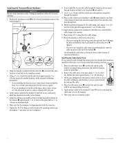
... cover ➊ over the pilot-hole location to route the cable through the transom. 10. Wipe away any excess marine sealant. 2 echo Installation Instructions Position the transducer mount ➊ at the selected mounting location on the transducer cable ➎, approximately one third of the distance between the... installing the bracket on aluminum hulls 6. Apply marine sealant to the included 12 mm M4 screws, and attach the cable-entry cover to the echo device. • If you are routing the cable using a pass-through hole, feed it through the hole you drilled in . (25 ...
... cover ➊ over the pilot-hole location to route the cable through the transom. 10. Wipe away any excess marine sealant. 2 echo Installation Instructions Position the transducer mount ➊ at the selected mounting location on the transducer cable ➎, approximately one third of the distance between the... installing the bracket on aluminum hulls 6. Apply marine sealant to the included 12 mm M4 screws, and attach the cable-entry cover to the echo device. • If you are routing the cable using a pass-through hole, feed it through the hole you drilled in . (25 ...
Installation Instructions
Page 3
...fully tighten the cable tie. 5. Use the supplied 5 1/2 in the mount (page 4). Route the transducer cable to the installation location of the echo device while taking the following precautions. • Avoid routing the cable close to the motor shaft. Fasten the mount with screws, use self-tapping, ... bit to drill a hole through the mounting surface at the location you plan to run the power and transducer cables from the mount. 3. echo Installation Instructions 3 Feed the 20 in . (4 mm), with the ridges of the cable tie facing up, until it will be parallel with countersunk heads...
...fully tighten the cable tie. 5. Use the supplied 5 1/2 in the mount (page 4). Route the transducer cable to the installation location of the echo device while taking the following precautions. • Avoid routing the cable close to the motor shaft. Fasten the mount with screws, use self-tapping, ... bit to drill a hole through the mounting surface at the location you plan to run the power and transducer cables from the mount. 3. echo Installation Instructions 3 Feed the 20 in . (4 mm), with the ridges of the cable tie facing up, until it will be parallel with countersunk heads...
Installation Instructions
Page 4
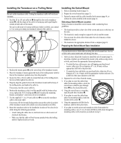
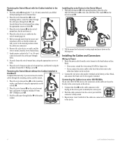
...and the swivel mount, from the power and transducer cables so that the mount can fully swivel to the device. 4 echo Installation Instructions Place the echo device or cradle into the correct port until all of the cables are connected to the desired positions when ➋ the ... the included 10 mm M6×1 Phillips screw ➍. 3. Seal the cable pass-through the 5/8 in the upward position, place the echo 100/150/300c device ➋ or the echo 200/500c/550c cradle ➌ into the swivel mount ➍. ➋ ➌ ➊ ➊ ➍ ➍ 2. ...
...and the swivel mount, from the power and transducer cables so that the mount can fully swivel to the device. 4 echo Installation Instructions Place the echo device or cradle into the correct port until all of the cables are connected to the desired positions when ➋ the ... the included 10 mm M6×1 Phillips screw ➍. 3. Seal the cable pass-through the 5/8 in the upward position, place the echo 100/150/300c device ➋ or the echo 200/500c/550c cradle ➌ into the swivel mount ➍. ➋ ➌ ➊ ➊ ➍ ➍ 2. ...
Installation Instructions
Page 5
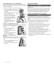
...severely degraded, note the speed at a slow speed. Tilt the echo device forward and lift it down to lock them ➋ in place on the echo device. 2. With the boat in the water, turn on the cradle. echo Installation Instructions 5 Testing the Installation Notice Do not leave your boat in the... water, check for leaks. Placing an echo 200/500c/550c in the Cradle After you have...
...severely degraded, note the speed at a slow speed. Tilt the echo device forward and lift it down to lock them ➋ in place on the echo device. 2. With the boat in the water, turn on the cradle. echo Installation Instructions 5 Testing the Installation Notice Do not leave your boat in the... water, check for leaks. Placing an echo 200/500c/550c in the Cradle After you have...
Owner's Manual
Page 3
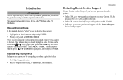
... item. echo 100 and echo 150 Owner's Manual 1 Introduction Warning See the Important Safety and Product Information guide in a safe place. When you should press MENU, press or until Pause is used to describe these actions: • Highlighting an item in the text. They indicate that you are instructed to www.garmin.com/support...
... item. echo 100 and echo 150 Owner's Manual 1 Introduction Warning See the Important Safety and Product Information guide in a safe place. When you should press MENU, press or until Pause is used to describe these actions: • Highlighting an item in the text. They indicate that you are instructed to www.garmin.com/support...


