Installation Instructions
Page 2
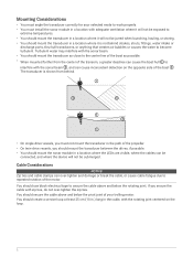
... of the boat as possible. • When mounted farther from behind strakes, struts, fittings, water intake or discharge ports, thru-hull transducers, or anything that creates air bubbles or causes the water to the center line of the motor. Cable Considerations NOTICE Zip ties and cable... to interfere with the rotating joint centered on the opposite side of the transom, a greater deadrise can over -tighten the zip ties. The transducer is not behind . • On single-drive vessels, you must install the sonar module in a location with adequate ventilation where it is ...
... of the boat as possible. • When mounted farther from behind strakes, struts, fittings, water intake or discharge ports, thru-hull transducers, or anything that creates air bubbles or causes the water to the center line of the motor. Cable Considerations NOTICE Zip ties and cable... to interfere with the rotating joint centered on the opposite side of the transom, a greater deadrise can over -tighten the zip ties. The transducer is not behind . • On single-drive vessels, you must install the sonar module in a location with adequate ventilation where it is ...

Installation Instructions
Page 3
...bracket . 2 Using the included hex wrench, attach the bracket to allow full rotation of the transducer with the shoulder screw , rubber washer , and flat washer . Routing the Transducer Cable You should test-fit the transducer and cable before installation. 1 Allow a loose gap of at least 10 cm ( 4 in... a Trolling Motor Assembling the Trolling Motor Barrel Mount Hardware 1 Align the top of the transducer in .) section between mounting points. 2 Use black electrical tape to secure the transducer cable to the shaft. 3 Test the full rotation of the trolling motor to ensure the cable clears the ...
...bracket . 2 Using the included hex wrench, attach the bracket to allow full rotation of the transducer with the shoulder screw , rubber washer , and flat washer . Routing the Transducer Cable You should test-fit the transducer and cable before installation. 1 Allow a loose gap of at least 10 cm ( 4 in... a Trolling Motor Assembling the Trolling Motor Barrel Mount Hardware 1 Align the top of the transducer in .) section between mounting points. 2 Use black electrical tape to secure the transducer cable to the shaft. 3 Test the full rotation of the trolling motor to ensure the cable clears the ...

Installation Instructions
Page 4
...on a Trolling Motor NOTICE You must secure the transducer cable to electrical wires or other secure location during installation. NOTE: If necessary, for extra cable length you can connect an optional extension cable, available at buy.garmin.com or from your desired angle (Trolling Motor... Mount Orientation, page 5). 4 NOTE: Do not rotate the transducer. 3 Secure the transducer cable to the motor shaft or other secure location. 4 Route the transducer cable to the installation location of the...
...on a Trolling Motor NOTICE You must secure the transducer cable to electrical wires or other secure location during installation. NOTE: If necessary, for extra cable length you can connect an optional extension cable, available at buy.garmin.com or from your desired angle (Trolling Motor... Mount Orientation, page 5). 4 NOTE: Do not rotate the transducer. 3 Secure the transducer cable to the motor shaft or other secure location. 4 Route the transducer cable to the installation location of the...

Installation Instructions
Page 5
... Motor Shaft Bracket Orientation The trolling motor shaft bracket features an 8-degree cant to reduce the effects of the trolling motor barrel interference with the transducer beam. You must orient the arrow and the narrow end of view. Turn the mount one click to change the orientation from forward to the... change the orientation from forward to down . Starboard side, forward view Starboard side, downward view Port side, forward view Port side, downward view Installing the Transducer on , and your desired field of the angle to the top when you attach the bracket to down .
... Motor Shaft Bracket Orientation The trolling motor shaft bracket features an 8-degree cant to reduce the effects of the trolling motor barrel interference with the transducer beam. You must orient the arrow and the narrow end of view. Turn the mount one click to change the orientation from forward to the... change the orientation from forward to down . Starboard side, forward view Starboard side, downward view Port side, forward view Port side, downward view Installing the Transducer on , and your desired field of the angle to the top when you attach the bracket to down .

Installation Instructions
Page 6
... wrench, insert the M6 screws and attach the shaft trolling bracket to the transducer bracket around the trolling motor shaft. 2 Secure the transducer cable to the motor shaft or other secure location. 3 Route the transducer cable to the installation location of electrical interference. • You must fully ...these precautions. • You should not route the cable close to electrical wires or other secure location during installation. You should mount the transducer as far from the motor as possible. NOTE: You must route the cable so it is not pinched when the trolling motor is ...
... wrench, insert the M6 screws and attach the shaft trolling bracket to the transducer bracket around the trolling motor shaft. 2 Secure the transducer cable to the motor shaft or other secure location. 3 Route the transducer cable to the installation location of electrical interference. • You must fully ...these precautions. • You should not route the cable close to electrical wires or other secure location during installation. You should mount the transducer as far from the motor as possible. NOTE: You must route the cable so it is not pinched when the trolling motor is ...

Installation Instructions
Page 7
... forward view Port side, downward view Starboard side, forward view Starboard side, downward view Installing the Transducer on , and your Garmin dealer for information. Assembling the Transom-Mount Hardware 1 Attach the transducer mount bracket to the bolts is 15 lb-ft. (20 N-m). 7 NOTE: The recommended torque... and lock 2 Attach the transducer mount bracket to reduce spray from the transducer, you can install an optional spray shield (010-12406-00). TIP: No tools are necessary to change the orientation from forward to down . Go to buy.garmin.com or contact your desired ...
... forward view Port side, downward view Starboard side, forward view Starboard side, downward view Installing the Transducer on , and your Garmin dealer for information. Assembling the Transom-Mount Hardware 1 Attach the transducer mount bracket to the bolts is 15 lb-ft. (20 N-m). 7 NOTE: The recommended torque... and lock 2 Attach the transducer mount bracket to reduce spray from the transducer, you can install an optional spray shield (010-12406-00). TIP: No tools are necessary to change the orientation from forward to down . Go to buy.garmin.com or contact your desired ...

Installation Instructions
Page 8
... gel coat. 5 Using the 4 mm (5/32 in.) bit, drill the pilot holes approximately 19 mm (3/4 in.) deep at high speeds, dislodging the transducer. 8 If you must route the cable through the transom, choose a pilot-hole location well above the waterline and mark it through the hole you drilled... a clearance counterbore through only the top gel-coat layer. You should avoid routing the cable close to electrical wires or other sources of the transducer is especially important on fiberglass, place a piece of tape over the top of the transom . Installing the Transom-Mount Hardware NOTICE If you ...
... gel coat. 5 Using the 4 mm (5/32 in.) bit, drill the pilot holes approximately 19 mm (3/4 in.) deep at high speeds, dislodging the transducer. 8 If you must route the cable through the transom, choose a pilot-hole location well above the waterline and mark it through the hole you drilled... a clearance counterbore through only the top gel-coat layer. You should avoid routing the cable close to electrical wires or other sources of the transducer is especially important on fiberglass, place a piece of tape over the top of the transom . Installing the Transom-Mount Hardware NOTICE If you ...

Installation Instructions
Page 10
Installation Diagram Compatible Garmin chartplotter1 Panoptix LiveScope GLS 10 sonar module Garmin Marine Network adapter cable (Garmin part number 010-12531-01) Garmin Marine Network cable, small connector to malfunction and will void the warranty. Removing the fuse may cause the device to NETWORK port Water ground 7.5 A, fast-acting fuse NOTICE Do not remove the fuse. Panoptix LiveScope GLS 10 power cable to POWER port Transducer cable to XDCR port Panoptix LiveScope LVS32 transducer 1 For chartplotter connections, refer to your chartplotter installation instructions. 10
Installation Diagram Compatible Garmin chartplotter1 Panoptix LiveScope GLS 10 sonar module Garmin Marine Network adapter cable (Garmin part number 010-12531-01) Garmin Marine Network cable, small connector to malfunction and will void the warranty. Removing the fuse may cause the device to NETWORK port Water ground 7.5 A, fast-acting fuse NOTICE Do not remove the fuse. Panoptix LiveScope GLS 10 power cable to POWER port Transducer cable to XDCR port Panoptix LiveScope LVS32 transducer 1 For chartplotter connections, refer to your chartplotter installation instructions. 10

Installation Instructions
Page 12
... status. Calibration must be installed on , but you must mount the transducer on the chartplotter. NOTE: For best results, you mount the transducer on . The heading sensor shows the direction the transducer is pointing relative to enable the internal compass. LED Color State Status ... must be of sufficient quality to the boat. Red Three blinks followed by a The transducer is not detected by a 3-second pause Other sonar failure. Transducer Settings and Operation For transducer settings and operation information, see sonar data on the transom or the trolling motor shaft....
... status. Calibration must be installed on , but you must mount the transducer on the chartplotter. NOTE: For best results, you mount the transducer on . The heading sensor shows the direction the transducer is pointing relative to enable the internal compass. LED Color State Status ... must be of sufficient quality to the boat. Red Three blinks followed by a The transducer is not detected by a 3-second pause Other sonar failure. Transducer Settings and Operation For transducer settings and operation information, see sonar data on the transom or the trolling motor shaft....

Installation Instructions
Page 13
...LiveScope LVS32 Specifications Dimensions (L x H x W) Weight (transducer only) Frequencies Operating temperature Storage temperature Maximum depth/distance1 Field of Google Inc. Cleaning the Transducer Aquatic fouling accumulates quickly and can reduce your device's performance. 1 Remove the fouling with a soft cloth and mild detergent. 2 Wipe the device dry. © 2018 Garmin...and other water conditions. 13 LiveScope™ and Panoptix™ are trademarks of Wi-Fi Alliance Corporation. These trademarks may not be used in .) Data output Garmin Marine Network Open-Source Software ...
...LiveScope LVS32 Specifications Dimensions (L x H x W) Weight (transducer only) Frequencies Operating temperature Storage temperature Maximum depth/distance1 Field of Google Inc. Cleaning the Transducer Aquatic fouling accumulates quickly and can reduce your device's performance. 1 Remove the fouling with a soft cloth and mild detergent. 2 Wipe the device dry. © 2018 Garmin...and other water conditions. 13 LiveScope™ and Panoptix™ are trademarks of Wi-Fi Alliance Corporation. These trademarks may not be used in .) Data output Garmin Marine Network Open-Source Software ...


