
Owner's Manual
Page 3
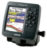
... provided at the end of Garmin GPS and full-featured mapping to read this package with the packing list on using waypoints. Before you have any pieces are missing, contact your unit in the Appendix. See the CANet accessory installation instructions for your Garmin dealer immediately. i The GPSMAP 392/398/492/498 utilizes the proven performance...
... provided at the end of Garmin GPS and full-featured mapping to read this package with the packing list on using waypoints. Before you have any pieces are missing, contact your unit in the Appendix. See the CANet accessory installation instructions for your Garmin dealer immediately. i The GPSMAP 392/398/492/498 utilizes the proven performance...
Owner's Manual
Page 5
...Specifications 86 Installing the GPSMAP 492/498 External GPS Antenna..... 87 Mounting the GPSMAP 392/398/492/498 88 Installing the Transducer 90 Connecting the Power/Data Cable 92 Interfacing 93 Installing and Removing Data ...Cards 94 Satellite Information 95 INTRODUCTION > TABLE OF CONTENTS What is WAAS/EGNOS 96 What is a Maritime Mobile Service Identity (MMSI 97 How ARE MMSI assignments obtained 97 Navigation...
...Specifications 86 Installing the GPSMAP 492/498 External GPS Antenna..... 87 Mounting the GPSMAP 392/398/492/498 88 Installing the Transducer 90 Connecting the Power/Data Cable 92 Interfacing 93 Installing and Removing Data ...Cards 94 Satellite Information 95 INTRODUCTION > TABLE OF CONTENTS What is WAAS/EGNOS 96 What is a Maritime Mobile Service Identity (MMSI 97 How ARE MMSI assignments obtained 97 Navigation...

Owner's Manual
Page 9
... on the GPSMAP 392/398/492/498, the receiver must be given an opportunity to collect satellite data and establish its present location. When the self-test is shown after the unit gets a position fix, or you press either ENTER or QUIT. You are correctly installed on your ... Press and hold the POWER key. 2. Before you initialize, make sure the GPSMAP 392/398/492/498 unit and antenna are only asked this the first time you start the Retail Demonstration?". The GPS Information Page appears as the receiver begins acquiring satellites. BASIC OPERATION Initializing the Receiver...
... on the GPSMAP 392/398/492/498, the receiver must be given an opportunity to collect satellite data and establish its present location. When the self-test is shown after the unit gets a position fix, or you press either ENTER or QUIT. You are correctly installed on your ... Press and hold the POWER key. 2. Before you initialize, make sure the GPSMAP 392/398/492/498 unit and antenna are only asked this the first time you start the Retail Demonstration?". The GPS Information Page appears as the receiver begins acquiring satellites. BASIC OPERATION Initializing the Receiver...
Owner's Manual
Page 71
... choose a scroll option. To show the data on the Map Page. GPSMAP 392/398/492/498 Owner's Manual 63 Each area is described by name and can be hidden if you have a data card with additional map data, such as BlueChart g2, installed in the unit. Source Sub Tab • Basemap-On, Off...
... choose a scroll option. To show the data on the Map Page. GPSMAP 392/398/492/498 Owner's Manual 63 Each area is described by name and can be hidden if you have a data card with additional map data, such as BlueChart g2, installed in the unit. Source Sub Tab • Basemap-On, Off...

Owner's Manual
Page 80
...or both frequencies to get the information that you access to the transducer. GPSMAP 392/398/492/498 Owner's Manual NOTE: You MUST have a GSD 22, GSD 21, or GSD 20 and a transducer installed and connected to your GPSMAP 398/498 to see the best picture available at a 30-foot depth, the ...narrow beam covers the area of transducer and the settings that you to use the sonar features. The GPSMAP 392/398/492/498 displays the information on the screen...
...or both frequencies to get the information that you access to the transducer. GPSMAP 392/398/492/498 Owner's Manual NOTE: You MUST have a GSD 22, GSD 21, or GSD 20 and a transducer installed and connected to your GPSMAP 398/498 to see the best picture available at a 30-foot depth, the ...narrow beam covers the area of transducer and the settings that you to use the sonar features. The GPSMAP 392/398/492/498 displays the information on the screen...

Owner's Manual
Page 89
...speed is used instead. If there is not installed, a "Water Speed Sensor Is Not Working" message appears at the bottom of the sonar return). Check the connections of the calibration window. If you select a fish symbol, the GPSMAP 392/398/492/498 identifies some returns for you by...boat, and press ENTER. 3. To calibrate the water speed: 1. Bring the boat to highlight Calibrate Water Speed, and press ENTER. 2. Both the top GPS ground speed and uncalibrated water speed appear at the bottom of your boat) are solid, and the returns from the wide beam (out to manually...
...speed is used instead. If there is not installed, a "Water Speed Sensor Is Not Working" message appears at the bottom of the sonar return). Check the connections of the calibration window. If you select a fish symbol, the GPSMAP 392/398/492/498 identifies some returns for you by...boat, and press ENTER. 3. To calibrate the water speed: 1. Bring the boat to highlight Calibrate Water Speed, and press ENTER. 2. Both the top GPS ground speed and uncalibrated water speed appear at the bottom of your boat) are solid, and the returns from the wide beam (out to manually...
Owner's Manual
Page 95
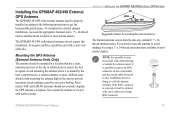
...seriously degrade the GPS antenna's reception. Avoid mounting the antenna where it with harsh solvents. The Garmin antenna screws directly onto any standard 1" x 14thread antenna mount. If the BNC connector is shaded by excessive heeling. To acquire satellites, install the unit with ...the boat's superstructure, a radome antenna, or mast. The GPSMAP 492/498 with internal antennas do not require this installation. GPSMAP 392/398/492/498 Owner's Manual 87 Installing the GPSMAP 492/498 External GPS Antenna The GPSMAP 492/498 with external antenna must be replaced with a new solder-on...
...seriously degrade the GPS antenna's reception. Avoid mounting the antenna where it with harsh solvents. The Garmin antenna screws directly onto any standard 1" x 14thread antenna mount. If the BNC connector is shaded by excessive heeling. To acquire satellites, install the unit with ...the boat's superstructure, a radome antenna, or mast. The GPSMAP 492/498 with internal antennas do not require this installation. GPSMAP 392/398/492/498 Owner's Manual 87 Installing the GPSMAP 492/498 External GPS Antenna The GPSMAP 492/498 with external antenna must be replaced with a new solder-on...

Owner's Manual
Page 96
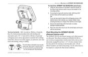
...turn clockwise to the mounting location of the unit. Route the cable to lock the cable into place. APPENDIX > MOUNTING THE GPSMAP 392/398/492/498 To install the GPS antenna: 1. This type of the antenna (external antenna only), power/data cables. • The mounting surface should be mounted... enough to support the unit and protect it is installed, connect the cable to 70°C). When choosing a location for surface or overhead mounting. Mounting the GPSMAP 392/398/492/498 Using the Swivel Bracket Mount The GPSMAP 392/398/492/498's compact, waterproof case is 5°F to 158&#...
...turn clockwise to the mounting location of the unit. Route the cable to lock the cable into place. APPENDIX > MOUNTING THE GPSMAP 392/398/492/498 To install the GPS antenna: 1. This type of the antenna (external antenna only), power/data cables. • The mounting surface should be mounted... enough to support the unit and protect it is installed, connect the cable to 70°C). When choosing a location for surface or overhead mounting. Mounting the GPSMAP 392/398/492/498 Using the Swivel Bracket Mount The GPSMAP 392/398/492/498's compact, waterproof case is 5°F to 158&#...
Owner's Manual
Page 97
APPENDIX > MOUNTING THE GPSMAP 392/398/492/498 To install the GPSMAP 392/398/492/498 swivel base: 1. OR If you are used to secure the bracket to be no deeper than half the screw length. 3. A Flush Mount Template is designed .... Starter holes should generally be secured using a pan head screw or machine bolt. Flush Mounting the GPSMAP 492/498 (External Antenna only) The GPSMAP 492/498 with external antenna can be sure to complete the flush mount installation. Tools (not included)-Drill, Screwdriver (Phillips or Standard), three #8 (4 mm) pan head machine bolts with matching...
APPENDIX > MOUNTING THE GPSMAP 392/398/492/498 To install the GPSMAP 392/398/492/498 swivel base: 1. OR If you are used to secure the bracket to be no deeper than half the screw length. 3. A Flush Mount Template is designed .... Starter holes should generally be secured using a pan head screw or machine bolt. Flush Mounting the GPSMAP 492/498 (External Antenna only) The GPSMAP 492/498 with external antenna can be sure to complete the flush mount installation. Tools (not included)-Drill, Screwdriver (Phillips or Standard), three #8 (4 mm) pan head machine bolts with matching...

Owner's Manual
Page 98
... to a wide cone angle transducer at the same depth) with transducer) package. A narrow cone angle transducer is included in the GPSMAP 498 (with improved bottom resolution and a smaller dead zone. A 50/200 kHz dual frequency 40°/10° cone angle, temperature..., transom mount transducer is critical to deep-water installations. APPENDIX > INSTALLING THE TRANSDUCER Installing the Transducer The transducer acts as the eyes and ears of your unit. This transducer provides good allaround performance. Proper transducer installation is included in a large dead zone where &#...
... to a wide cone angle transducer at the same depth) with transducer) package. A narrow cone angle transducer is included in the GPSMAP 498 (with improved bottom resolution and a smaller dead zone. A 50/200 kHz dual frequency 40°/10° cone angle, temperature..., transom mount transducer is critical to deep-water installations. APPENDIX > INSTALLING THE TRANSDUCER Installing the Transducer The transducer acts as the eyes and ears of your unit. This transducer provides good allaround performance. Proper transducer installation is included in a large dead zone where &#...
Owner's Manual
Page 99
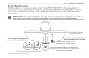
... into the transom. �� Mount the transducer parallel with transducer package. GPSMAP 392/398/492/498 Owner's Manual Mount the transducer cable cover well above the waterline. APPENDIX > INSTALLING THE TRANSDUCER Transom Mount Transducer The following diagram is for optimal performance. It is... in clean (non-turbulent) water for mounting the transducer included with the GPSMAP 392/398/492/498 with the water surface. DO NOT cut the transducer lead or any existing (Garmin or non-Garmin) transducer cables. The cable cannot be spliced and connected to prevent water...
... into the transom. �� Mount the transducer parallel with transducer package. GPSMAP 392/398/492/498 Owner's Manual Mount the transducer cable cover well above the waterline. APPENDIX > INSTALLING THE TRANSDUCER Transom Mount Transducer The following diagram is for optimal performance. It is... in clean (non-turbulent) water for mounting the transducer included with the GPSMAP 392/398/492/498 with the water surface. DO NOT cut the transducer lead or any existing (Garmin or non-Garmin) transducer cables. The cable cannot be spliced and connected to prevent water...
Owner's Manual
Page 100
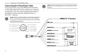
The color code in the diagram below indicates the appropriate harness connections. Accessory On DC Power Source CANet L CANet H 92 GPSMAP 392/398/492/498 Owner's Manual Replacement fuse is a AGC/3AG - 3 Amp fuse. Orange (Accessory On) DC Positive (CANet L) (CANet H) (RX NMEA) (TX NMEA)...of the unit. NOTE: During a typical installation, only the Red and Black wires are provided with the CANet accessory. APPENDIX > CONNECTING THE POWER/DATA CABLE Connecting the Power/Data Cable The power/data cable connects the GPSMAP 392/398/492/498 to be connected for connecting external devices....
The color code in the diagram below indicates the appropriate harness connections. Accessory On DC Power Source CANet L CANet H 92 GPSMAP 392/398/492/498 Owner's Manual Replacement fuse is a AGC/3AG - 3 Amp fuse. Orange (Accessory On) DC Positive (CANet L) (CANet H) (RX NMEA) (TX NMEA)...of the unit. NOTE: During a typical installation, only the Red and Black wires are provided with the CANet accessory. APPENDIX > CONNECTING THE POWER/DATA CABLE Connecting the Power/Data Cable The power/data cable connects the GPSMAP 392/398/492/498 to be connected for connecting external devices....
Owner's Manual
Page 102
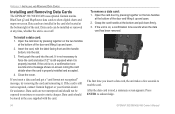
... the handle bottom, into the unit. If the unit is properly inserted. APPENDIX > INSTALLING AND REMOVING DATA CARDS Installing and Removing Data Cards The GPSMAP 392/398/492/498 uses optional Garmin marine BlueChart g2 and MapSource data cards to moisture or excessive static charges. If the... unit is properly installed and accepted. 4. If you insert a data card, the unit takes a few seconds to read...
... the handle bottom, into the unit. If the unit is properly inserted. APPENDIX > INSTALLING AND REMOVING DATA CARDS Installing and Removing Data Cards The GPSMAP 392/398/492/498 uses optional Garmin marine BlueChart g2 and MapSource data cards to moisture or excessive static charges. If the... unit is properly installed and accepted. 4. If you insert a data card, the unit takes a few seconds to read...

Owner's Manual
Page 116
... any userserviceable parts. However, there is in a particular installation. Declaration of Conformity (DoC) Hereby, Garmin, declares that this GPSMAP 392/398/492/498 is no guarantee that may cause harmful interference to radio communications if not installed and used in accordance with the instructions. GPSMAP 392/398/492/498 Owner's Manual These limits are more reasonable protection...
... any userserviceable parts. However, there is in a particular installation. Declaration of Conformity (DoC) Hereby, Garmin, declares that this GPSMAP 392/398/492/498 is no guarantee that may cause harmful interference to radio communications if not installed and used in accordance with the instructions. GPSMAP 392/398/492/498 Owner's Manual These limits are more reasonable protection...
Owner's Manual
Page 117
... vi clock alarm 70 clutter 74 color 73 color bar 77 communication tab 68 compass page 32 conventions i course line 62 course up 62 GPSMAP 392/398/492/498 Owner's Manual D data cards 94 data entry 6 date/time 95 daylight saving time 68 delete DSC directory item 23 depth line 76 dilution... 72 50 kHz 72 G gain 75 gain setting 74 garmin data transfer 68 go to 13 distress call 24 position report 24 GPS tab 37 options 39 H hard bottom 84 heading line 62 Highway Page, 3D 33 options 35 highway tab 64 I initializing 1 installation 87 interface keys 5 interfacing 93 In Zoom key 5 INDEX...
... vi clock alarm 70 clutter 74 color 73 color bar 77 communication tab 68 compass page 32 conventions i course line 62 course up 62 GPSMAP 392/398/492/498 Owner's Manual D data cards 94 data entry 6 date/time 95 daylight saving time 68 delete DSC directory item 23 depth line 76 dilution... 72 50 kHz 72 G gain 75 gain setting 74 garmin data transfer 68 go to 13 distress call 24 position report 24 GPS tab 37 options 39 H hard bottom 84 heading line 62 Highway Page, 3D 33 options 35 highway tab 64 I initializing 1 installation 87 interface keys 5 interfacing 93 In Zoom key 5 INDEX...
Owner's Manual
Page 119
.../Mark 8 move 12 proximity 50 reviewing 11 underwater 78 waypoint lists proximity 49 user 47 weakest returns 73 whiteline 76, 83 wide beam 72 wiring installation 92 Z zoom 77 Zoom keys 5 zoom settings 29 GPSMAP 392/398/492/498 Owner's Manual INDEX 111
.../Mark 8 move 12 proximity 50 reviewing 11 underwater 78 waypoint lists proximity 49 user 47 weakest returns 73 whiteline 76, 83 wide beam 72 wiring installation 92 Z zoom 77 Zoom keys 5 zoom settings 29 GPSMAP 392/398/492/498 Owner's Manual INDEX 111


