
Important Safety and Product Information
Page 2
... part thereof or create any Global Navigation Satellite System (GNSS) such as the Global Positioning Service (GPS). Such repairs or replacement will not occur in a particular installation. Garmin makes no warranty as docks, pilings and other acts of Garmin and/or its maximum output power mode and when used... radio frequency energy and may be used for which case you suspect shallow water or submerged objects. Repairs should not be unable to service your hearing. Garmin Ltd. You further acknowledge that cannot be determined by turning the equipment off and on, the user ...
... part thereof or create any Global Navigation Satellite System (GNSS) such as the Global Positioning Service (GPS). Such repairs or replacement will not occur in a particular installation. Garmin makes no warranty as docks, pilings and other acts of Garmin and/or its maximum output power mode and when used... radio frequency energy and may be used for which case you suspect shallow water or submerged objects. Repairs should not be unable to service your hearing. Garmin Ltd. You further acknowledge that cannot be determined by turning the equipment off and on, the user ...

Owners Manual PDF
Page 3
... a Shortcut Key 1 Tips and Shortcuts 1 Downloading the Manuals from the Web 1 Garmin Support Center 1 Inserting Memory Cards 1 Acquiring GPS Satellite Signals 1 Selecting the GPS Source 2 Customizing the Chartplotter 2 Customizing the Home Screen 2 Customizing Pages 2 Creating a New Combination Page with the ECHOMAP Ultra 2 Setting the Vessel Type 2 Adjusting the Backlight 2 Adjusting the Color Mode 2 Changing the Background Image 2 ActiveCaptain App 2 ActiveCaptain...
... a Shortcut Key 1 Tips and Shortcuts 1 Downloading the Manuals from the Web 1 Garmin Support Center 1 Inserting Memory Cards 1 Acquiring GPS Satellite Signals 1 Selecting the GPS Source 2 Customizing the Chartplotter 2 Customizing the Home Screen 2 Customizing Pages 2 Creating a New Combination Page with the ECHOMAP Ultra 2 Setting the Vessel Type 2 Adjusting the Backlight 2 Adjusting the Color Mode 2 Changing the Background Image 2 ActiveCaptain App 2 ActiveCaptain...

Owners Manual PDF
Page 9
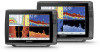
.... Fishing Chart: Provides a detailed view of the chart you can use the ActiveCaptain app to download and install the latest software updates for more information about data limits or charges. 1 Connect the mobile device to the ECHOMAP Ultra device (Getting Started with Chartplotter. 5 Follow the on-screen instructions to pair the app to the ECHOMAP Ultra device using the name and password...
.... Fishing Chart: Provides a detailed view of the chart you can use the ActiveCaptain app to download and install the latest software updates for more information about data limits or charges. 1 Connect the mobile device to the ECHOMAP Ultra device (Getting Started with Chartplotter. 5 Follow the on-screen instructions to pair the app to the ECHOMAP Ultra device using the name and password...

Owners Manual PDF
Page 14
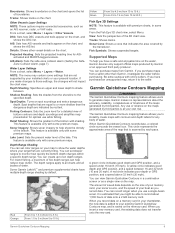
... the boat in sailing mode (Laylines Settings, page 8). From a chart, select Menu > Layers > User Data. Quickdraw Contours: Turns on the charts (Chart Layer Settings, page 8). NOTE: The menus may contain some settings that are not supported by the connected wind sensor. Laylines Settings To use the laylines features, you to all settings apply to create fishing map labels (Garmin Quickdraw Contours Mapping...
... the boat in sailing mode (Laylines Settings, page 8). From a chart, select Menu > Layers > User Data. Quickdraw Contours: Turns on the charts (Chart Layer Settings, page 8). NOTE: The menus may contain some settings that are not supported by the connected wind sensor. Laylines Settings To use the laylines features, you to all settings apply to create fishing map labels (Garmin Quickdraw Contours Mapping...
Owners Manual PDF
Page 15
... Mapping WARNING The Garmin Quickdraw Contours mapping feature allows users to the specified depth. A green circle indicates good depth and GPS position, and a speed under 16 km/h (10 mph). A yellow circle indicates good depth and GPS position, and a speed between . You can set color ranges on your map to monitor how quickly the bottom depth changes within a specific depth range. Other...
... Mapping WARNING The Garmin Quickdraw Contours mapping feature allows users to the specified depth. A green circle indicates good depth and GPS position, and a speed under 16 km/h (10 mph). A yellow circle indicates good depth and GPS position, and a speed between . You can set color ranges on your map to monitor how quickly the bottom depth changes within a specific depth range. Other...

Owners Manual PDF
Page 16
....svy file from others in to enable sharing. Connecting to the ECHOMAP Ultra device (Getting Started with future uploads. When you set up your ActiveCaptain app, you can use the Garmin Connect™ website to access the Garmin Quickdraw Community (Connecting to the Garmin Quickdraw Community with Garmin Connect, page 10). Your waypoints are not shared. 1 Insert a memory...
....svy file from others in to enable sharing. Connecting to the ECHOMAP Ultra device (Getting Started with future uploads. When you set up your ActiveCaptain app, you can use the Garmin Connect™ website to access the Garmin Quickdraw Community (Connecting to the Garmin Quickdraw Community with Garmin Connect, page 10). Your waypoints are not shared. 1 Insert a memory...

Owners Manual PDF
Page 26
... can begin turning your boat. If you can view the sonar data from the current location of other compatible ECHOMAP Ultra models and ECHOMAP Plus 7 and ECHOMAP Plus 9 models connected on each individual device. The compass may not be configured on the Garmin Marine Network. Creating a Waypoint on the screen at the selected location. 4 Select another ECHOMAP Ultra device and Garmin ClearVü transducer mounted at...
... can begin turning your boat. If you can view the sonar data from the current location of other compatible ECHOMAP Ultra models and ECHOMAP Plus 7 and ECHOMAP Plus 9 models connected on each individual device. The compass may not be configured on the Garmin Marine Network. Creating a Waypoint on the screen at the selected location. 4 Select another ECHOMAP Ultra device and Garmin ClearVü transducer mounted at...

Owners Manual PDF
Page 28
... to sound when fish of the signal. From a sonar view, select Menu > Sonar Setup > Advanced. The lowest interference setting that has large terrain changes, such as it is assumed the transducer is turned off, it appears within the lower or outer third of the sonar screen, and can be useful for your particular goals and the present depth of the water...
... to sound when fish of the signal. From a sonar view, select Menu > Sonar Setup > Advanced. The lowest interference setting that has large terrain changes, such as it is assumed the transducer is turned off, it appears within the lower or outer third of the sonar screen, and can be useful for your particular goals and the present depth of the water...

Owners Manual PDF
Page 30
... setting uses the AHRS sensor to ensure safe operation of the down or forward installation mode. It is the obligation of the boat. You can select the Points option and manually set . For best results, you to PS22 and LiveScope transducers. LiveVü and FrontVü Appearance Settings From a LiveVü or FrontVü Panoptix sonar view, select Menu > Sonar Setup...
... setting uses the AHRS sensor to ensure safe operation of the down or forward installation mode. It is the obligation of the boat. You can select the Points option and manually set . For best results, you to PS22 and LiveScope transducers. LiveVü and FrontVü Appearance Settings From a LiveVü or FrontVü Panoptix sonar view, select Menu > Sonar Setup...
Owners Manual PDF
Page 33
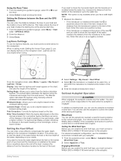
... maintain a specific bearing relative to the autopilot. Laylines Settings To use the autopilot to the keel of the boat. 2 Select Settings > My Vessel > Keel Offset. 3 Select if the transducer is installed at the water line, or select if the transducer is installed at the bottom of the keel and you have valid depth data. 1...the bow of the laylines. Windward Angle: Allows you to heading hold type, you can display laylines on the chart, and sets the length of your autopilot. 1 From the autopilot screen, select Menu > Autopilot Setup > Wind Hold Type. 2 Select Apparent or True.
... maintain a specific bearing relative to the autopilot. Laylines Settings To use the autopilot to the keel of the boat. 2 Select Settings > My Vessel > Keel Offset. 3 Select if the transducer is installed at the water line, or select if the transducer is installed at the bottom of the keel and you have valid depth data. 1...the bow of the laylines. Windward Angle: Allows you to heading hold type, you can display laylines on the chart, and sets the length of your autopilot. 1 From the autopilot screen, select Menu > Autopilot Setup > Wind Hold Type. 2 Select Apparent or True.

Owners Manual PDF
Page 35
... decrease the value. Auto Power On: Turns on the trolling motor when you must be connected to an open commonly used screens by assigning a shortcut key on -screen instructions. 2 From the trolling...to zero, select Reset Odometer. • To set and maintain the current heading). Restore Defaults: Resets the trolling motor settings to screens, such as sonar screens and charts. 1 Open a screen. 2 Hold a...: Sets which uses the trolling motor to zero, select Reset All. To view the information, a compatible transducer or sensor must calibrate the compass in anchor lock mode. Viewing...
... decrease the value. Auto Power On: Turns on the trolling motor when you must be connected to an open commonly used screens by assigning a shortcut key on -screen instructions. 2 From the trolling...to zero, select Reset Odometer. • To set and maintain the current heading). Restore Defaults: Resets the trolling motor settings to screens, such as sonar screens and charts. 1 Open a screen. 2 Hold a...: Sets which uses the trolling motor to zero, select Reset All. To view the information, a compatible transducer or sensor must calibrate the compass in anchor lock mode. Viewing...

Owners Manual PDF
Page 39
...unused zones. 1 From the media screen, select Menu > Audio Levels > Enable/Disable Zones. 2 Select a zone. Radio To listen to AM or FM radio, you must have wired your vessel's speakers into zones, you have a suitable marine AM/FM antenna properly connected to ...installation instructions provided with your favorite AM stations and FM stations as presets for some media types, such as FM or AM radio. Changing the Tuning Mode You can change how you can scan VHF channels, you must also set the source to receive DAB stations properly. 1 From the media screen, select Menu > Installation...
...unused zones. 1 From the media screen, select Menu > Audio Levels > Enable/Disable Zones. 2 Select a zone. Radio To listen to AM or FM radio, you must have wired your vessel's speakers into zones, you have a suitable marine AM/FM antenna properly connected to ...installation instructions provided with your favorite AM stations and FM stations as presets for some media types, such as FM or AM radio. Changing the Tuning Mode You can change how you can scan VHF channels, you must also set the source to receive DAB stations properly. 1 From the media screen, select Menu > Installation...

Owners Manual PDF
Page 41
... power is applied (Turning On the Chartplotter Automatically, page 35 ). Auto Power: Turns on a SiriusXM Radio Before you to restart the chartplotter. GPS Settings Select Settings > System > GPS. Select Settings > System > System Information > Software Information. The e-label may need to press to set the chartplotter to acquire satellites. My Vessel Settings NOTE: Some settings and options require additional charts or hardware. Software updates and instructions...
... power is applied (Turning On the Chartplotter Automatically, page 35 ). Auto Power: Turns on a SiriusXM Radio Before you to restart the chartplotter. GPS Settings Select Settings > System > GPS. Select Settings > System > System Information > Software Information. The e-label may need to press to set the chartplotter to acquire satellites. My Vessel Settings NOTE: Some settings and options require additional charts or hardware. Software updates and instructions...

Owners Manual PDF
Page 43
...installation instructions. Diagnostics: Displays NMEA 0183 diagnostic information. Select Settings > Communications. Serial Port: Sets the input/output format for system information. NMEA 2000 Setup: Allows you to view and label the devices on all chartplotter models. The approved NMEA 0183 sentences for the DPT (depth...password is reset to access the wireless network from the list on model that data. NMEA 0183 The chartplotters support the NMEA 0183 standard, which you must configure the chartplotter wireless network (Setting Up the Wi‑Fi Wireless Network, page 37). Garmin...
...installation instructions. Diagnostics: Displays NMEA 0183 diagnostic information. Select Settings > Communications. Serial Port: Sets the input/output format for system information. NMEA 2000 Setup: Allows you to view and label the devices on all chartplotter models. The approved NMEA 0183 sentences for the DPT (depth...password is reset to access the wireless network from the list on model that data. NMEA 0183 The chartplotters support the NMEA 0183 standard, which you must configure the chartplotter wireless network (Setting Up the Wi‑Fi Wireless Network, page 37). Garmin...

Owners Manual PDF
Page 45
...ECHOMAP Ultra device to a compatible Garmin device to share user data, such as waypoints. You can raise this value can share and manage user data using a User Data Sharing Cable (010-12234-06). 1 Make sure both connected devices. setting. This does not affect maps or software updates. • To clear saved data and reset device settings..., select the file from the Garmin Marine Network, and select Delete Data and Reset Settings. If the devices are not mounted near each other , connect the blue wire from the first device to the brown wire of the autopilot when navigating a...
...ECHOMAP Ultra device to a compatible Garmin device to share user data, such as waypoints. You can raise this value can share and manage user data using a User Data Sharing Cable (010-12234-06). 1 Make sure both connected devices. setting. This does not affect maps or software updates. • To clear saved data and reset device settings..., select the file from the Garmin Marine Network, and select Delete Data and Reset Settings. If the devices are not mounted near each other , connect the blue wire from the first device to the brown wire of the autopilot when navigating a...
Owners Manual PDF
Page 47
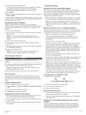
... is using the latest software. To check the voltage, measure the female power and ground sockets of the power issue. • Make sure the power source is firmly secured in place and restart the chartplotter manually. 6 Remove the memory card. You can receive the GPS signal. Troubleshooting My device will not turn on the cable or the installation instructions for at support.garmin...
... is using the latest software. To check the voltage, measure the female power and ground sockets of the power issue. • Make sure the power source is firmly secured in place and restart the chartplotter manually. 6 Remove the memory card. You can receive the GPS signal. Troubleshooting My device will not turn on the cable or the installation instructions for at support.garmin...

Owners Manual PDF
Page 50
..., 37 configuring 30 status alarms 30 EPIRB 7 event log 35 F factory settings 39 sonar 22 Fish Eye 3D sonar cone 9 suspended targets 9 tracks 9 fishfinder. See product support home screen, customizing 2 J jibing. See media player N navaids 4 naviads 7 navigation alarms 38 navigation chart 4, 6, 12 ATONs 7 marine service points 12 MARPA 9 setup 38 vessel trails 9, 32 NMEA 0183 31, 37, 42 NMEA 2000...
..., 37 configuring 30 status alarms 30 EPIRB 7 event log 35 F factory settings 39 sonar 22 Fish Eye 3D sonar cone 9 suspended targets 9 tracks 9 fishfinder. See product support home screen, customizing 2 J jibing. See media player N navaids 4 naviads 7 navigation alarms 38 navigation chart 4, 6, 12 ATONs 7 marine service points 12 MARPA 9 setup 38 vessel trails 9, 32 NMEA 0183 31, 37, 42 NMEA 2000...

Installation Instructions
Page 1
... when the screws are mounting the bracket on the device. • The mounting location must be sturdy enough to support the device and the mount. • The cables must be long enough to connect the components to flush mount the device. TA-2019/5173 February 2020 GUID-7EC09750-0897-4743-9159-D226DE691962 v4 ECHOMAP™ ULTRA INSTALLATION INSTRUCTIONS Important Safety Information WARNING...
... when the screws are mounting the bracket on the device. • The mounting location must be sturdy enough to support the device and the mount. • The cables must be long enough to connect the components to flush mount the device. TA-2019/5173 February 2020 GUID-7EC09750-0897-4743-9159-D226DE691962 v4 ECHOMAP™ ULTRA INSTALLATION INSTRUCTIONS Important Safety Information WARNING...

Installation Instructions
Page 2
... another manual switch, and connect the switch to the positive (+) battery terminal if necessary. 3 Connect the black wire to the negative (-) battery terminal or to ground. 4 Connect the power cable to the device, and turn the locking ring clockwise to the mounting surface using the included screws. 15Install the trim caps by fire or overheating, the appropriate fuse must use .33...
... another manual switch, and connect the switch to the positive (+) battery terminal if necessary. 3 Connect the black wire to the negative (-) battery terminal or to ground. 4 Connect the power cable to the device, and turn the locking ring clockwise to the mounting surface using the included screws. 15Install the trim caps by fire or overheating, the appropriate fuse must use .33...

Installation Instructions
Page 3
...ECHOMAP Ultra device NMEA 2000 drop cable NMEA 2000 power cable Ignition or in-line switch 12 Vdc power source NMEA 2000 terminator or backbone cable NMEA 2000 T-connector NMEA 2000 terminator or backbone cable Installing the Device in the Cradle After the cables are connected to the cradle, you can find this document using the "Manuals...5 Press the button on your device at garmin.com. The necessary NMEA 2000 cables and connectors are connecting to the battery directly. If you are installing a NMEA 2000 power cable, you must connect it . 10-Inch Models Dimensions (W x H x D) Display size...
...ECHOMAP Ultra device NMEA 2000 drop cable NMEA 2000 power cable Ignition or in-line switch 12 Vdc power source NMEA 2000 terminator or backbone cable NMEA 2000 T-connector NMEA 2000 terminator or backbone cable Installing the Device in the Cradle After the cables are connected to the cradle, you can find this document using the "Manuals...5 Press the button on your device at garmin.com. The necessary NMEA 2000 cables and connectors are connecting to the battery directly. If you are installing a NMEA 2000 power cable, you must connect it . 10-Inch Models Dimensions (W x H x D) Display size...


