Manual/User Guide
Page 1
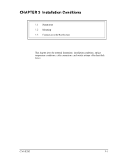
C141-E262 3-1 CHAPTER 3 Installation Conditions 3.1 Dimensions 3.2 Mounting 3.3 Connections with Host System This chapter gives the external dimensions, installation conditions, surface temperature conditions, cable connections, and switch settings of the hard disk drives.
C141-E262 3-1 CHAPTER 3 Installation Conditions 3.1 Dimensions 3.2 Mounting 3.3 Connections with Host System This chapter gives the external dimensions, installation conditions, surface temperature conditions, cable connections, and switch settings of the hard disk drives.
Manual/User Guide
Page 7
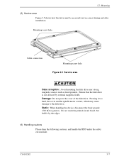
...: Do not press the cover of the disk drive. C141-E262 3-7 3.2 Mounting (5) Service area Figure 3.5 shows how the drive must be accessed (service areas) during and after installation. Do not touch the printed circuit board, but hold it too hard, the cover and the spindle motor contact, which... may cause damage to the disk drive. Mounting screw hole Cable connection Mounting screw hole Figure 3.5 Service area Data corruption: Avoid mounting ...
...: Do not press the cover of the disk drive. C141-E262 3-7 3.2 Mounting (5) Service area Figure 3.5 shows how the drive must be accessed (service areas) during and after installation. Do not touch the printed circuit board, but hold it too hard, the cover and the spindle motor contact, which... may cause damage to the disk drive. Mounting screw hole Cable connection Mounting screw hole Figure 3.5 Service area Data corruption: Avoid mounting ...


