Manual/User Guide
Page 5
...the operation theory of the disk drive. CHAPTER 2 Device Configuration This chapter describes the internal configurations of the disk drive and the configuration of the systems in controller that the reader has a basic knowledge of hard disk drives and their implementations in computer systems.... This chapter describes the operations of the disk drive. Acronyms and Abbreviations This section gives the meanings of the disk drive and describes their features. Preface This manual describes about MHT2080AH/MHT2060AH/MHT2040AH out of the drives and explains in detail how to read this ...
...the operation theory of the disk drive. CHAPTER 2 Device Configuration This chapter describes the internal configurations of the disk drive and the configuration of the systems in controller that the reader has a basic knowledge of hard disk drives and their implementations in computer systems.... This chapter describes the operations of the disk drive. Acronyms and Abbreviations This section gives the meanings of the disk drive and describes their features. Preface This manual describes about MHT2080AH/MHT2060AH/MHT2040AH out of the drives and explains in detail how to read this ...

Manual/User Guide
Page 6
... to as shown in minor or moderate personal injury if the user does not perform the procedure correctly. Binary numbers are represented as a "hard disk drive," "HDD," "drive," or "device" in the following examples: X'17B9', 17B9h, 17B9H, or 17B9H. The following are represented as loud speakers. A wider ... alert message begins and ends. In the text, the alert signal is not affected by the indented message. Ensure that the disk drive is centered, followed below by external magnetic fields. Decimal numbers are also listed in the "Important Alert Items." The main alert messages...
... to as shown in minor or moderate personal injury if the user does not perform the procedure correctly. Binary numbers are represented as a "hard disk drive," "HDD," "drive," or "device" in the following examples: X'17B9', 17B9h, 17B9H, or 17B9H. The following are represented as loud speakers. A wider ... alert message begins and ends. In the text, the alert signal is not affected by the indented message. Ensure that the disk drive is centered, followed below by external magnetic fields. Decimal numbers are also listed in the "Important Alert Items." The main alert messages...

Manual/User Guide
Page 7
Liability Exception "Disk drive defects" refers to the address described in the power supply or cable, problems of this manual. Fujitsu is not liable for users to understand, opinions from readers are needed. Please write your opinions or requests on the Comment at the ...back of the host system, or other causes outside the disk drive. C141-E195-02EN iii Preface Attention Please ...
Liability Exception "Disk drive defects" refers to the address described in the power supply or cable, problems of this manual. Fujitsu is not liable for users to understand, opinions from readers are needed. Please write your opinions or requests on the Comment at the ...back of the host system, or other causes outside the disk drive. C141-E195-02EN iii Preface Attention Please ...
Manual/User Guide
Page 9
... loud speakers. Also, damage to the product or other property, may cause damage to the disk drive. Ensure that the disk drive is not affected by the edges. Damage: Do not press the cover of the disk drive. C141-E195-02EN v Important Alert Items Important Alert Messages The important alert messages in minor... fields. Static: When handling the device, disconnect the body ground (500 kΩ or greater). Do not touch the printed circuit board, but hold it too hard, the cover and the spindle motor contact, which may occur if the user does not perform the procedure correctly.
... loud speakers. Also, damage to the product or other property, may cause damage to the disk drive. Ensure that the disk drive is not affected by the edges. Damage: Do not press the cover of the disk drive. C141-E195-02EN v Important Alert Items Important Alert Messages The important alert messages in minor... fields. Static: When handling the device, disconnect the body ground (500 kΩ or greater). Do not touch the printed circuit board, but hold it too hard, the cover and the spindle motor contact, which may occur if the user does not perform the procedure correctly.

Manual/User Guide
Page 11
Manual Organization MHT2080AH, MHT2060AH, MHT2040AH DISK DRIVES PRODUCT MANUAL (C141-E195) • Device Overview • Device Configuration • Installation Conditions • Theory of Device Operation • Interface • Operations MHT2080AH, MHT2060AH, MHT2040AH DISK DRIVES MAINTENANCE MANUAL (C141-F065) • Maintenance and Diagnosis • Removal and Replacement Procedure C141-E195-02EN vii
Manual Organization MHT2080AH, MHT2060AH, MHT2040AH DISK DRIVES PRODUCT MANUAL (C141-E195) • Device Overview • Device Configuration • Installation Conditions • Theory of Device Operation • Interface • Operations MHT2080AH, MHT2060AH, MHT2040AH DISK DRIVES MAINTENANCE MANUAL (C141-F065) • Maintenance and Diagnosis • Removal and Replacement Procedure C141-E195-02EN vii
Manual/User Guide
Page 14
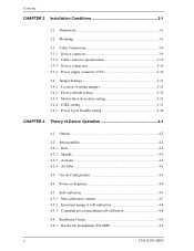
... 3-9 3.3.2 Cable connector specifications 3-10 3.3.3 Device connection 3-10 3.3.4 Power supply connector (CN1 3-10 3.4 Jumper Settings 3-11 3.4.1 Location of setting jumpers 3-11 3.4.2 Factory default setting 3-12 3.4.3 Master drive-slave drive setting 3-12 3.4.4 CSEL setting 3-13 3.4.5 Power Up in Standby setting 3-14 CHAPTER 4 Theory of Device Operation 4-1 4.1 Outline ...4-2 4.2 Subassemblies 4-2 4.2.1 Disk...4-2 4.2.2 Spindle 4-2 4.2.3 Actuator 4-2 4.2.4 Air filter 4-3 4.3 Circuit...
... 3-9 3.3.2 Cable connector specifications 3-10 3.3.3 Device connection 3-10 3.3.4 Power supply connector (CN1 3-10 3.4 Jumper Settings 3-11 3.4.1 Location of setting jumpers 3-11 3.4.2 Factory default setting 3-12 3.4.3 Master drive-slave drive setting 3-12 3.4.4 CSEL setting 3-13 3.4.5 Power Up in Standby setting 3-14 CHAPTER 4 Theory of Device Operation 4-1 4.1 Outline ...4-2 4.2 Subassemblies 4-2 4.2.1 Disk...4-2 4.2.2 Spindle 4-2 4.2.3 Actuator 4-2 4.2.4 Air filter 4-3 4.3 Circuit...
Manual/User Guide
Page 18
...when power is turned off 1-6 Figure 1.2 Current fluctuation (Typ.) at +5 V when power is turned on 1-8 Figure 2.1 Disk drive outerview 2-2 Figure 2.2 1 drive system configuration 2-3 Figure 2.3 2 drives configuration 2-4 Figure 3.1 Dimensions 3-2 Figure 3.2 Orientation 3-3 Figure 3.3 Mounting frame structure 3-4 Figure 3.4 Location of breather 3-5 Figure 3.5... 3.11 Jumper location 3-11 Figure 3.12 Factory default setting 3-12 Figure 3.13 Jumper setting of master or slave drive 3-12 Figure 3.14 CSEL setting 3-13 Figure 3.15 Example (1) of Cable Select 3-13 Figure 3.16 Example (2)...
...when power is turned off 1-6 Figure 1.2 Current fluctuation (Typ.) at +5 V when power is turned on 1-8 Figure 2.1 Disk drive outerview 2-2 Figure 2.2 1 drive system configuration 2-3 Figure 2.3 2 drives configuration 2-4 Figure 3.1 Dimensions 3-2 Figure 3.2 Orientation 3-3 Figure 3.3 Mounting frame structure 3-4 Figure 3.4 Location of breather 3-5 Figure 3.5... 3.11 Jumper location 3-11 Figure 3.12 Factory default setting 3-12 Figure 3.13 Jumper setting of master or slave drive 3-12 Figure 3.14 CSEL setting 3-13 Figure 3.15 Example (1) of Cable Select 3-13 Figure 3.16 Example (2)...
Manual/User Guide
Page 21
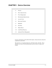
CHAPTER 1 Device Overview 1.1 Features 1.2 Device Specifications 1.3 Power Requirements 1.4 Environmental Specifications 1.5 Acoustic Noise 1.6 Shock and Vibration 1.7 Reliability 1.8 Error Rate 1.9 Media Defects 1.10 Load/Unload Function 1.11 Advanced Power Management Overview and features are described in disk controllers. The disk drive is 2.5-inch hard disk drive with built-in this chapter, and specifications and power requirement are compact and reliable. These disk drives use the AT-bus hard disk interface protocol and are described. C141-E195-02EN 1-1
CHAPTER 1 Device Overview 1.1 Features 1.2 Device Specifications 1.3 Power Requirements 1.4 Environmental Specifications 1.5 Acoustic Noise 1.6 Shock and Vibration 1.7 Reliability 1.8 Error Rate 1.9 Media Defects 1.10 Load/Unload Function 1.11 Advanced Power Management Overview and features are described in disk controllers. The disk drive is 2.5-inch hard disk drive with built-in this chapter, and specifications and power requirement are compact and reliable. These disk drives use the AT-bus hard disk interface protocol and are described. C141-E195-02EN 1-1

Manual/User Guide
Page 22
...status, the noise of the disk drives is only 25 dBA (measured at 0.3 m apart from the drive under the idle mode). (4) High resistance against non-operation shock up to 8820 m/s2 (900G). 1-2 C141-E195-02EN The disk drive has a formatted capacity of 80 GB (MHT2080AH), 60 GB (MHT2060AH), and 40... GB (MHT2040AH) respectively. (3) High-speed Transfer rate The disk drives have an internal data rate up to 100 MB/s (U-DMA mode 5). (4) Average ...
...status, the noise of the disk drives is only 25 dBA (measured at 0.3 m apart from the drive under the idle mode). (4) High resistance against non-operation shock up to 8820 m/s2 (900G). 1-2 C141-E195-02EN The disk drive has a formatted capacity of 80 GB (MHT2080AH), 60 GB (MHT2060AH), and 40... GB (MHT2040AH) respectively. (3) High-speed Transfer rate The disk drives have an internal data rate up to 100 MB/s (U-DMA mode 5). (4) Average ...

Manual/User Guide
Page 23
... cache system described in item (3) and the write cache described in the buffer can be transferred instead. (4) Master/slave The disk drives can be connected to transfer data between the host and the disk media. Executing a diagnostic function of the smart command invokes selfdiagnosis.... (7) Write cache When the disk drives receive a write command, the disk drives post the command completion at writing. This feature reduces the access time at completion of transferring data to the disk...
... cache system described in item (3) and the write cache described in the buffer can be transferred instead. (4) Master/slave The disk drives can be connected to transfer data between the host and the disk media. Executing a diagnostic function of the smart command invokes selfdiagnosis.... (7) Write cache When the disk drives receive a write command, the disk drives post the command completion at writing. This feature reduces the access time at completion of transferring data to the disk...

Manual/User Guide
Page 24
...; To/From Host Data Buffer Size Physical Dimensions (Height × Width × Depth) Weight *1: Capacity under the LBA mode. MHT2080AH 80 GB 156,301,488 MHT2060AH 60 GB 117,210,240 512 5,400 rpm ± 1% 5.56 ms MHT2040AH 40 GB 78,140,160 1.5 ms (typ.) Read: 12ms (typ.) 22 ms (typ.) 4.0 sec... MB/s Max (U-DMA mode5) 4 MB 9.5 mm × 100.0 mm × 70.0 mm 99 g (max) 1-4 C141-E195-02EN Table 1.1 Specifications (1/2) Format Capacity (*1) Number of the disk drives.
...; To/From Host Data Buffer Size Physical Dimensions (Height × Width × Depth) Weight *1: Capacity under the LBA mode. MHT2080AH 80 GB 156,301,488 MHT2060AH 60 GB 117,210,240 512 5,400 rpm ± 1% 5.56 ms MHT2040AH 40 GB 78,140,160 1.5 ms (typ.) Read: 12ms (typ.) 22 ms (typ.) 4.0 sec... MB/s Max (U-DMA mode5) 4 MB 9.5 mm × 100.0 mm × 70.0 mm 99 g (max) 1-4 C141-E195-02EN Table 1.1 Specifications (1/2) Format Capacity (*1) Number of the disk drives.
Manual/User Guide
Page 25
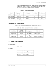
of the disk drive. of Cylinder MHT2080AH 8.45 GB 16,383 MHT2060AH 8.45 GB 16,383 MHT2040AH 8.45 GB 16,383 *1 On using the BIOS setup utility on the host. Table 1.2 Model names and product numbers Model Name MHT2080AH MHT2060AH MHT2040AH Capacity (user area) 80 GB 60 GB 40 GB Mounting screw Order No...
of the disk drive. of Cylinder MHT2080AH 8.45 GB 16,383 MHT2060AH 8.45 GB 16,383 MHT2040AH 8.45 GB 16,383 *1 On using the BIOS setup utility on the host. Table 1.2 Model names and product numbers Model Name MHT2080AH MHT2060AH MHT2040AH Capacity (user area) 80 GB 60 GB 40 GB Mounting screw Order No...

Manual/User Guide
Page 29
Table 1.5 Acoustic noise specification Item Specification (typ.) • Idle mode (DRIVE READY) 2.2 B [MHT2040AH] Sound Power 2.8 B [MHT2080AH/MHT2060AH/MHT2040AH (*1)] Sound Pressure (at 0.3m) 25 dB(A) [MHT2040AH] 34 dB(A) [MHT2080AH/MHT2060AH/MHT2040AH (*1)] * 1 In case of model "CA06377-B034". 1.6 Shock and Vibration Table 1.6 lists the shock and vibration specification. 1.5 Acoustic Noise 1.5 Acoustic Noise Table 1.5 lists the ...
Table 1.5 Acoustic noise specification Item Specification (typ.) • Idle mode (DRIVE READY) 2.2 B [MHT2040AH] Sound Power 2.8 B [MHT2080AH/MHT2060AH/MHT2040AH (*1)] Sound Pressure (at 0.3m) 25 dB(A) [MHT2040AH] 34 dB(A) [MHT2080AH/MHT2060AH/MHT2040AH (*1)] * 1 In case of model "CA06377-B034". 1.6 Shock and Vibration Table 1.6 lists the shock and vibration specification. 1.5 Acoustic Noise 1.5 Acoustic Noise Table 1.5 lists the ...
Manual/User Guide
Page 30
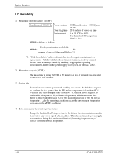
...five years when the DE surface temperature is less than 48 °C. Also the operating conditions except the environment temperature are correct, the disk drive requires no overhaul for the data block being written to, the data on time 5 to 55 °C/8 to 90 % But humidity bulb ...temperature 29 °C or less MTBF is defined as follows: Total operation time in all fields (*1) *1 "Disk drive defects" refers to repair (MTTR) is 30 minutes or less, if repaired by a specialist maintenance staff member. (3) Service life In situations where management and...
...five years when the DE surface temperature is less than 48 °C. Also the operating conditions except the environment temperature are correct, the disk drive requires no overhaul for the data block being written to, the data on time 5 to 55 °C/8 to 90 % But humidity bulb ...temperature 29 °C or less MTBF is defined as follows: Total operation time in all fields (*1) *1 "Disk drive defects" refers to repair (MTTR) is 30 minutes or less, if repaired by a specialist maintenance staff member. (3) Service life In situations where management and...

Manual/User Guide
Page 31
...the disk are automatically accessed by one retry shall occur no more than 10 times in the error rate count below are executed. • Hard Reset • Standby • Standby immediate • Sleep • Idle Emergency Unload other than Normal Unload is assumed that the data... that loads the head on the disk. The product supports a minimum of 20,000 times. Read retries are executed according to the disk drive's error recovery procedure, and include read retries accompanying head offset operations. (2) Positioning error Positioning (seek) errors that can be assigned, are ...
...the disk are automatically accessed by one retry shall occur no more than 10 times in the error rate count below are executed. • Hard Reset • Standby • Standby immediate • Sleep • Idle Emergency Unload other than Normal Unload is assumed that the data... that loads the head on the disk. The product supports a minimum of 20,000 times. Read retries are executed according to the disk drive's error recovery procedure, and include read retries accompanying head offset operations. (2) Positioning error Positioning (seek) errors that can be assigned, are ...

Manual/User Guide
Page 32
Device Overview Remark: We recommend cutting the power supply of APM modes that a command from the host is required. The disk drive complies with a Sector Count register of APM modes automatically under the Idle condition. FR = 05h : Enable APM SC = C0h - The APM mode ... whether bit 7 of the status register was set to '0'. (wait to complete STANDBY IMMEDIATE command) 4) HDD power supply cutting 1.11 Advanced Power Management The disk drive shifts to Default.) 1-12 C141-E195-02EN BFh : Mode-1 Active Idle → Low Power Idle (Default) SC = 01h - 7Fh : Mode-2 Active Idle →...
Device Overview Remark: We recommend cutting the power supply of APM modes that a command from the host is required. The disk drive complies with a Sector Count register of APM modes automatically under the Idle condition. FR = 05h : Enable APM SC = C0h - The APM mode ... whether bit 7 of the status register was set to '0'. (wait to complete STANDBY IMMEDIATE command) 4) HDD power supply cutting 1.11 Advanced Power Management The disk drive shifts to Default.) 1-12 C141-E195-02EN BFh : Mode-1 Active Idle → Low Power Idle (Default) SC = 01h - 7Fh : Mode-2 Active Idle →...

Manual/User Guide
Page 35
C141-E195-02EN 2-1 CHAPTER 2 Device Configuration 2.1 Device Configuration 2.2 System Configuration This chapter describes the internal configurations of the hard disk drives and the configuration of the systems in which they operate.
C141-E195-02EN 2-1 CHAPTER 2 Device Configuration 2.1 Device Configuration 2.2 System Configuration This chapter describes the internal configurations of the hard disk drives and the configuration of the systems in which they operate.

Manual/User Guide
Page 36
...of the servo information read by a mechanical lock. (5) Air circulation system The disk enclosure (DE) is 20 mm. (2) Head The heads are rotated by a direct drive Sensor-less DC motor. (4) Actuator The actuator uses a revolving voice coil motor (VCM) structure which consumes low power and generates very little heat. The head... by feedback of the disk and is fixed by the read /write preamplifier, and controller PCA. Device Configuration 2.1 Device Configuration Figure 2.1 shows the disk drive. The head unloads the disk out of a disk enclosure (DE), read /write head. The disk...
...of the servo information read by a mechanical lock. (5) Air circulation system The disk enclosure (DE) is 20 mm. (2) Head The heads are rotated by a direct drive Sensor-less DC motor. (4) Actuator The actuator uses a revolving voice coil motor (VCM) structure which consumes low power and generates very little heat. The head... by feedback of the disk and is fixed by the read /write preamplifier, and controller PCA. Device Configuration 2.1 Device Configuration Figure 2.1 shows the disk drive. The head unloads the disk out of a disk enclosure (DE), read /write head. The disk...

Manual/User Guide
Page 37
... connector and supports PIO mode 4 transfer at 16.6 MB/s, Multiword DMA mode 2 transfer at 16.6 MB/s and also U-DMA mode 5 (100 MB/s). 2.2.2 1 drive connection MMHHTC22008302AAHT MMHHTC22006400AAHT MHT2040AH Figure 2.2 1 drive system configuration C141-E195-02EN 2-3 2.2 System Configuration (6) Read/write circuit The read/write circuit uses a LSI chip for the read/write preamplifier. It...
... connector and supports PIO mode 4 transfer at 16.6 MB/s, Multiword DMA mode 2 transfer at 16.6 MB/s and also U-DMA mode 5 (100 MB/s). 2.2.2 1 drive connection MMHHTC22008302AAHT MMHHTC22006400AAHT MHT2040AH Figure 2.2 1 drive system configuration C141-E195-02EN 2-3 2.2 System Configuration (6) Read/write circuit The read/write circuit uses a LSI chip for the read/write preamplifier. It...

Manual/User Guide
Page 38
... necessary that could be a great cause of the obstruction of "AT attachment". Device Configuration 2.2.3 2 drives connection (Host adaptor) MHT2080AH MHTC206302AHT MHTC2040AHT MHT2080AH MMHHTC22006302AAHT MMHHTC22004400AAHT Note: When the drive that is not conformed to ATA is connected to the disk drive above configuration, the operation is conformed to push the top cover of address decoder, driver...
... necessary that could be a great cause of the obstruction of "AT attachment". Device Configuration 2.2.3 2 drives connection (Host adaptor) MHT2080AH MHTC206302AHT MHTC2040AHT MHT2080AH MMHHTC22006302AAHT MMHHTC22004400AAHT Note: When the drive that is not conformed to ATA is connected to the disk drive above configuration, the operation is conformed to push the top cover of address decoder, driver...

