Manual/User Guide
Page 5
... installation conditions, and switch settings of the disk drive. C141-E192-02EN i CHAPTER 5 Interface This chapter describes the interface specifications of the MHT Series, 2.5-inch hard disk drives. Glossary The glossary describes the technical terms that ...need to be understood to incorporate the drives into user systems. This manual assumes that is compatible with the ATA interface. Preface This manual describes MHT2080AT/ MHT2060AT/ MHT2040AT/ MHT2030AT...
... installation conditions, and switch settings of the disk drive. C141-E192-02EN i CHAPTER 5 Interface This chapter describes the interface specifications of the MHT Series, 2.5-inch hard disk drives. Glossary The glossary describes the technical terms that ...need to be understood to incorporate the drives into user systems. This manual assumes that is compatible with the ATA interface. Preface This manual describes MHT2080AT/ MHT2060AT/ MHT2040AT/ MHT2030AT...
Manual/User Guide
Page 14
Contents CHAPTER 3 Installation Conditions 3-1 3.1 Dimensions 3-2 3.2 Mounting 3-3 3.3 Cable Connections 3-9 3.3.1 Device connector 3-9 3.3.2 Cable connector specifications 3-10 3.3.3 Device connection 3-10 3.3.4 Power supply connector (CN1 3-11 3.4 Jumper Settings 3-11 3.4.1 Location of setting jumpers 3-11 3.4.2 Factory default setting 3-12 3.4.3 Master drive-slave drive setting 3-12 3.4.4 CSEL setting 3-13 3.4.5 Power Up in Standby setting 3-14 CHAPTER 4 Theory of Device Operation...
Contents CHAPTER 3 Installation Conditions 3-1 3.1 Dimensions 3-2 3.2 Mounting 3-3 3.3 Cable Connections 3-9 3.3.1 Device connector 3-9 3.3.2 Cable connector specifications 3-10 3.3.3 Device connection 3-10 3.3.4 Power supply connector (CN1 3-11 3.4 Jumper Settings 3-11 3.4.1 Location of setting jumpers 3-11 3.4.2 Factory default setting 3-12 3.4.3 Master drive-slave drive setting 3-12 3.4.4 CSEL setting 3-13 3.4.5 Power Up in Standby setting 3-14 CHAPTER 4 Theory of Device Operation...
Manual/User Guide
Page 20
... of model names and product numbers 1-5 Current and power dissipation 1-7 Environmental specifications 1-8 Acoustic noise specification 1-9 Shock and vibration specification 1-9 Table 3.1 Surface temperature measurement points and standard values..........3-6 Table 3.2 Cable connector specifications 3-10 Table 5.1 Signal assignment on the interface connector 5-3 Table 5.2 I/O registers 5-7 Table 5.3 Command code and parameters 5-15 Table 5.4 Information to be read by IDENTIFY...
... of model names and product numbers 1-5 Current and power dissipation 1-7 Environmental specifications 1-8 Acoustic noise specification 1-9 Shock and vibration specification 1-9 Table 3.1 Surface temperature measurement points and standard values..........3-6 Table 3.2 Cable connector specifications 3-10 Table 5.1 Signal assignment on the interface connector 5-3 Table 5.2 I/O registers 5-7 Table 5.3 Command code and parameters 5-15 Table 5.4 Information to be read by IDENTIFY...
Manual/User Guide
Page 21
These disk drives use the AT-bus hard disk interface protocol and are described. C141-E192-02EN 1-1 CHAPTER 1 Device Overview 1.1 Features 1.2 Device Specifications 1.3 Power Requirements 1.4 Environmental Specifications 1.5 Acoustic Noise 1.6 Shock and Vibration 1.7 Reliability 1.8 Error Rate 1.9 Media Defects 1.10 Load/Unload Function 1.11 Advanced Power Management Overview and features are described in disk controllers. The disk drive is 2.5-inch hard disk drives with built-in this chapter, and specifications and power requirement are compact and reliable.
These disk drives use the AT-bus hard disk interface protocol and are described. C141-E192-02EN 1-1 CHAPTER 1 Device Overview 1.1 Features 1.2 Device Specifications 1.3 Power Requirements 1.4 Environmental Specifications 1.5 Acoustic Noise 1.6 Shock and Vibration 1.7 Reliability 1.8 Error Rate 1.9 Media Defects 1.10 Load/Unload Function 1.11 Advanced Power Management Overview and features are described in disk controllers. The disk drive is 2.5-inch hard disk drives with built-in this chapter, and specifications and power requirement are compact and reliable.
Manual/User Guide
Page 24
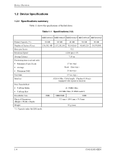
... • Average • Maximum (Full) 80 GB 60 GB 40 GB 30 GB 156,301,488 117,210,240 78,140,160 58,605,120 512 4,200 rpm ± 1% 7.14 ms 1.5 ms (typ.) Read: 12ms (typ.) 22 ms (typ.) 20 GB 39,070,080 Start time Interface Data Transfer Rate &#...8226; To/From Media • To/From Host 3.5 sec (typ.) ATA-6 (Max. Table 1.1 Specifications (1/2) MHT2080AT MHT2060AT MHT2040AT MHT2030AT MHT2020AT Format Capacity (*1) Number of the disk drives. Cable length: 18inches (0.46 m)) (equipped with...
... • Average • Maximum (Full) 80 GB 60 GB 40 GB 30 GB 156,301,488 117,210,240 78,140,160 58,605,120 512 4,200 rpm ± 1% 7.14 ms 1.5 ms (typ.) Read: 12ms (typ.) 22 ms (typ.) 20 GB 39,070,080 Start time Interface Data Transfer Rate &#...8226; To/From Media • To/From Host 3.5 sec (typ.) ATA-6 (Max. Table 1.1 Specifications (1/2) MHT2080AT MHT2060AT MHT2040AT MHT2030AT MHT2020AT Format Capacity (*1) Number of the disk drives. Cable length: 18inches (0.46 m)) (equipped with...
Manual/User Guide
Page 25
... been customized and have specifications that of the disk drive. The model name does not necessarily correspond to the product number as that are different from those for the units of model names and product numbers Model Name MHT2080AT MHT2060AT MHT2040AT MHT2030AT MHT2020AT Capacity (user area) 80 GB 60 GB 40 GB 30 GB 20 GB Mounting screw Order...
... been customized and have specifications that of the disk drive. The model name does not necessarily correspond to the product number as that are different from those for the units of model names and product numbers Model Name MHT2080AT MHT2060AT MHT2040AT MHT2030AT MHT2020AT Capacity (user area) 80 GB 60 GB 40 GB 30 GB 20 GB Mounting screw Order...
Manual/User Guide
Page 28
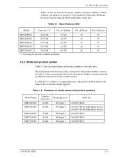
...power is abnormal. These prevent data from being destroyed and eliminates the need to 12,000 m 1-8 C141-E192-02EN Table 1.4 Environmental specifications Item Temperature • Operating • Non-operating • Thermal Gradient Humidity • Operating • Non-operating • Maximum ...Wet Bulb Altitude (relative to sea level) • Operating • Non-operating Specification 5 °C to 55 °C (ambient) 5 °C to 60 °C (disk enclosure surface) -40 °C to 65 °C 20 ...
...power is abnormal. These prevent data from being destroyed and eliminates the need to 12,000 m 1-8 C141-E192-02EN Table 1.4 Environmental specifications Item Temperature • Operating • Non-operating • Thermal Gradient Humidity • Operating • Non-operating • Maximum ...Wet Bulb Altitude (relative to sea level) • Operating • Non-operating Specification 5 °C to 55 °C (ambient) 5 °C to 60 °C (disk enclosure surface) -40 °C to 65 °C 20 ...
Manual/User Guide
Page 29
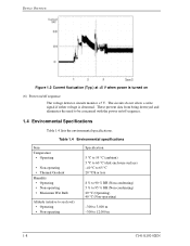
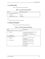
...Vibration (Swept sine, 1/4 octave per minute) • Operating • Non-operating Shock (half-sine pulse) • Operating • Non-operating Specification 5 to 500 Hz, 9.8m/s2 0-peak (1G 0-peak) (without non-recovered errors) 5 to 500 Hz, 49m/s2 0-peak (5G 0-peak...duration 1176 m/s2 0-peak (120G 0-peak) 11ms duration (no damage) C141-E192-02EN 1-9 Table 1.5 Acoustic noise specification Item • Idle mode (DRIVE READY) Sound Power Sound Pressure (at 0.3m) Specification (typical) 2.3B(A) 24.0dB(A) Note: Measure the noise from the cover top surface. 1.6 Shock and Vibration Table...
...Vibration (Swept sine, 1/4 octave per minute) • Operating • Non-operating Shock (half-sine pulse) • Operating • Non-operating Specification 5 to 500 Hz, 9.8m/s2 0-peak (1G 0-peak) (without non-recovered errors) 5 to 500 Hz, 49m/s2 0-peak (5G 0-peak...duration 1176 m/s2 0-peak (120G 0-peak) 11ms duration (no damage) C141-E192-02EN 1-9 Table 1.5 Acoustic noise specification Item • Idle mode (DRIVE READY) Sound Power Sound Pressure (at 0.3m) Specification (typical) 2.3B(A) 24.0dB(A) Note: Measure the noise from the cover top surface. 1.6 Shock and Vibration Table...
Manual/User Guide
Page 42
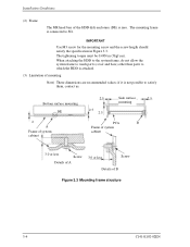
... the HDD disk enclosure (DE) is not possible to SG. IMPORTANT Use M3 screw for the mounting screw and the screw length should satisfy the specification in Figure 3.3.
... the HDD disk enclosure (DE) is not possible to SG. IMPORTANT Use M3 screw for the mounting screw and the screw length should satisfy the specification in Figure 3.3.
Manual/User Guide
Page 48
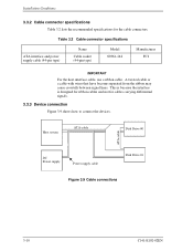
... is designed for ribbon cables and not for the cable connectors. Host system ATA-cable Disk Drive #0 ATA-cable DC Power supply Power supply cable Disk Drive #1 Figure 3.9 Cable connections 3-10 C141-E192-02EN Table 3.2 Cable connector specifications ATA interface and power supply cable (44-pin type) Name Cable socket (44-pin type...
... is designed for ribbon cables and not for the cable connectors. Host system ATA-cable Disk Drive #0 ATA-cable DC Power supply Power supply cable Disk Drive #1 Figure 3.9 Cable connections 3-10 C141-E192-02EN Table 3.2 Cable connector specifications ATA interface and power supply cable (44-pin type) Name Cable socket (44-pin type...
Manual/User Guide
Page 73
... for one revolution of the spindle motor based on the PHASE signal. The SVC starts a phase switching by charging or discharging the charge pump for a specific period, the MPU resets the SVC and starts from the SVC, and waits till the rotational speed reaches 4,200 rpm. When the rotational speed reaches...
... for one revolution of the spindle motor based on the PHASE signal. The SVC starts a phase switching by charging or discharging the charge pump for a specific period, the MPU resets the SVC and starts from the SVC, and waits till the rotational speed reaches 4,200 rpm. When the rotational speed reaches...
Manual/User Guide
Page 83
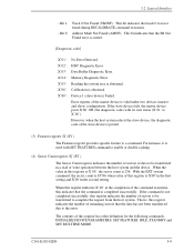
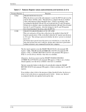
Bit 0: Track 0 Not Found (TK0NF). Error register of the master device is posted. (3) Features register (X'1F1') The Features register provides specific feature to a command. INITIALIZE DEVICE PARAMETERS, SET FEATURES, IDLE, STANDBY and SET MULTIPLE MODE. However, when the host system selects the slave device, the diagnostic ...
Bit 0: Track 0 Not Found (TK0NF). Error register of the master device is posted. (3) Features register (X'1F1') The Features register provides specific feature to a command. INITIALIZE DEVICE PARAMETERS, SET FEATURES, IDLE, STANDBY and SET MULTIPLE MODE. However, when the host system selects the slave device, the diagnostic ...
Manual/User Guide
Page 105
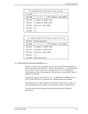
... ABORTED COMMAND error is posted. When the SC register is "number of heads minus 1") per cylinder with only CHS mode specification. C141-E192-02EN 5-31 The device ignores the L bit specification and operates with this command terminates normally. Upon receipt of this command are retained even after reset or power save operation...
... ABORTED COMMAND error is posted. When the SC register is "number of heads minus 1") per cylinder with only CHS mode specification. C141-E192-02EN 5-31 The device ignores the L bit specification and operates with this command terminates normally. Upon receipt of this command are retained even after reset or power save operation...
Manual/User Guide
Page 120
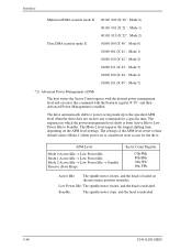
... Idle to Low Power Idle to the specified APM level when the drive does not receive any commands for the drive. The settings of the APM level revert to their default values (Mode-1) when power-on or a hardware reset occurs for a specific time. Interface Multiword DMA transfer mode X Ultra DMA transfer mode X 00100... head is loaded on the most inner position on the APM level settings. The Mode-2 level requires the longest shifting time, depending on media. The drive automatically shifts to power saving mode up to Standby.
... Idle to Low Power Idle to the specified APM level when the drive does not receive any commands for the drive. The settings of the APM level revert to their default values (Mode-1) when power-on or a hardware reset occurs for a specific time. Interface Multiword DMA transfer mode X Ultra DMA transfer mode X 00100... head is loaded on the most inner position on the APM level settings. The Mode-2 level requires the longest shifting time, depending on media. The drive automatically shifts to power saving mode up to Standby.
Manual/User Guide
Page 141
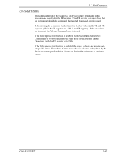
... values that are incorrect, the Aborted Command error is issued. 5.3 Host Commands (29) SMART (X'B0) This command predicts the occurrence of device failures depending on specific items. The values of items whose data is disabled, the device returns the Aborted Command error to subcommands other than those of the SMART Enable...
... values that are incorrect, the Aborted Command error is issued. 5.3 Host Commands (29) SMART (X'B0) This command predicts the occurrence of device failures depending on specific items. The values of items whose data is disabled, the device returns the Aborted Command error to subcommands other than those of the SMART Enable...
Manual/User Guide
Page 144
... ENABLE/DISABLE AUTO OFF-LINE: This sets automatic off . The host can predict failures in the enabled (when the SC register specification ≠ 00h) or disabled (when the SC register specification = 00) state. If there is switched on a medium. Alternative, the device must regularly issue the SMART READ DATA subcommand ...on, or since the last time that the user quickly backs up the data. 5-70 C141-E192-02EN This setting is preserved whether the drive's power is an attribute value exceeding the threshold, F4h and 2Ch are loaded into the CL and CH registers. If an attribute value is...
... ENABLE/DISABLE AUTO OFF-LINE: This sets automatic off . The host can predict failures in the enabled (when the SC register specification ≠ 00h) or disabled (when the SC register specification = 00) state. If there is switched on a medium. Alternative, the device must regularly issue the SMART READ DATA subcommand ...on, or since the last time that the user quickly backs up the data. 5-70 C141-E192-02EN This setting is preserved whether the drive's power is an attribute value exceeding the threshold, F4h and 2Ch are loaded into the CL and CH registers. If an attribute value is...
Manual/User Guide
Page 156
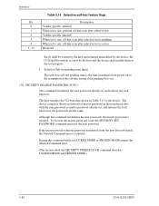
...the user password or master password transferred from power-on to the resumption of the off-line testing if the pending bit is set. (30) SECURITY DISABLE PASSWORD (X'F6') This command invalidates the user password already set to one, off-line scan after selective test is active. ... device. Interface Bit 0 1 2 3 4 5...15 Table 5.14 Selective self-test feature flags Description Vendor specific (unused) When set to one, perform off-line scan after selective test Vendor specific (unused) When set and releases the lock function. The host transfers the 512-byte data shown in minutes from...
...the user password or master password transferred from power-on to the resumption of the off-line testing if the pending bit is set. (30) SECURITY DISABLE PASSWORD (X'F6') This command invalidates the user password already set to one, off-line scan after selective test is active. ... device. Interface Bit 0 1 2 3 4 5...15 Table 5.14 Selective self-test feature flags Description Vendor specific (unused) When set to one, perform off-line scan after selective test Vendor specific (unused) When set and releases the lock function. The host transfers the 512-byte data shown in minutes from...
Manual/User Guide
Page 161
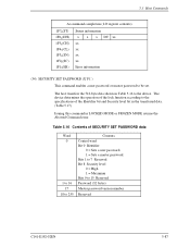
Table 5.16 Contents of SECURITY SET PASSWORD data Word 0 1 to 16 17 18 to the specifications of the lock function according to 255 Contents Control word Bit 0 Identifier 0 = Sets a user password. 1 = Sets a master password. The device determines the operation of the ...
Table 5.16 Contents of SECURITY SET PASSWORD data Word 0 1 to 16 17 18 to the specifications of the lock function according to 255 Contents Control word Bit 0 Identifier 0 = Sets a user password. 1 = Sets a master password. The device determines the operation of the ...
Manual/User Guide
Page 170
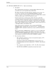
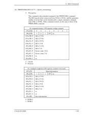
... 1, the highest address is the default value.) After a power-on sequence. Interface (39) SET MAX ADDRESS EXT (X'37'): Option (customizing) • Description This command limits specifications so that the highest address that is outside of the IDENTIFY DEVICE command response.
... 1, the highest address is the default value.) After a power-on sequence. Interface (39) SET MAX ADDRESS EXT (X'37'): Option (customizing) • Description This command limits specifications so that the highest address that is outside of the IDENTIFY DEVICE command response.
Manual/User Guide
Page 173
...(SC) P Sector count (15-8) 1F2h(SC) C Sector count (7-0) 1F1h(FR) P xx 1F1h(FR) C xx C: Current P: Previous At command completion (I/O registers contents to 10000h. The LBA specification is increased from 28 bits to 48 bits, and the maximum number of sectors that can be read) 1F7h(ST) 1F6h(DH) 1F5h(CH) 1 1F5h...
...(SC) P Sector count (15-8) 1F2h(SC) C Sector count (7-0) 1F1h(FR) P xx 1F1h(FR) C xx C: Current P: Previous At command completion (I/O registers contents to 10000h. The LBA specification is increased from 28 bits to 48 bits, and the maximum number of sectors that can be read) 1F7h(ST) 1F6h(DH) 1F5h(CH) 1 1F5h...
